Sign In
Upload
Download
Table of Contents
Contents
Add to my manuals
Delete from my manuals
Share
URL of this page:
HTML Link:
Bookmark this page
Add
Manual will be automatically added to "My Manuals"
Print this page
×
Bookmark added
×
Added to my manuals
Manuals
Brands
ProSeal Manuals
Laminator
25
Service manual
ProSeal 25 Service Manual
Hide thumbs
1
2
3
4
5
Table Of Contents
6
7
8
9
10
11
12
13
14
15
16
17
18
19
20
21
22
23
24
25
26
27
28
29
30
31
32
33
34
35
36
37
38
39
40
41
42
43
page
of
43
Go
/
43
Contents
Table of Contents
Troubleshooting
Bookmarks
Table of Contents
Table of Contents
Machine Characteristics
Machine Description
Machine Specifications
Installation
Electrical Requirements
Preinstallation
Setup
Theory of Operation
Workspace Requirements
Control Knob
Control Panel
Disassembly / Reassembly Procedures
Opening / Closing the Aluminium Top Cover
Feed-In Table
Plastic Side Covers
Heating Element
Software
Rear Panel
Solid State Relay
Adjustment Procedures
Laminating Pressure Adjustment
Nip Adjustment
Temperature Adjustment
Maintenance
Cleaning of the Machine
Cleaning of the Rollers by Service Technicians
Troubleshooting
Regular Cleaning of the Rollers by the Operator
Diagrams
Electrical Schematics
Schematic Installation Diagram Proseal 25 - 110V/60Hz
Schematic Installation Diagram Proseal 44 - 110V/60Hz
Schematic Diagram Control PCB 110V 50/60Hz
Schematic Diagram Controlpanel
Schematic Installation Diagram Proseal 25 - 230V/50Hz
Schematic Installation Diagram Proseal 44 - 230V/50Hz
Schematic Diagram Control PCB 230V 50/60Hz
110Vac/60Hz Machines
Certified Electrical Components Lists & Sparepart Codes
230Vac/50Hz Machines
Mechanical Spare Parts List
Mechanical Spare Parts List, Assembly Drawings & Exploded Views
Assembly Drawings & Exploded Views
Advertisement
Quick Links
1
Table of Contents
2
Machine Description
3
Theory of Operation
4
Control Knob
5
Opening / Closing the Aluminium Top Cover
6
Feed-In Table
7
Troubleshooting
Download this manual
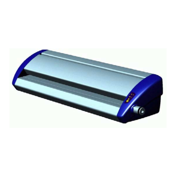
ProSeal 25 and 44
Laminator
Service Manual
Provided By
http://www.MyBinding.com
http://www.MyBindingBlog.com
Table of
Contents
Previous
Page
Next
Page
1
2
3
4
5
Advertisement
Table of Contents
Need help?
Do you have a question about the ProSeal 25 and is the answer not in the manual?
Ask a question
Questions and answers
Related Manuals for ProSeal ProSeal 25
Laminator ProSeal 44 Service Manual
(43 pages)
This manual is also suitable for:
Proseal 44
Table of Contents
Save PDF
Print
Rename the bookmark
Delete bookmark?
Delete from my manuals?
Login
Sign In
OR
Sign in with Facebook
Sign in with Google
Upload manual
Upload from disk
Upload from URL


Need help?
Do you have a question about the ProSeal 25 and is the answer not in the manual?
Questions and answers