Table of Contents
Advertisement
Quick Links
Download this manual
See also:
Instruction Manual
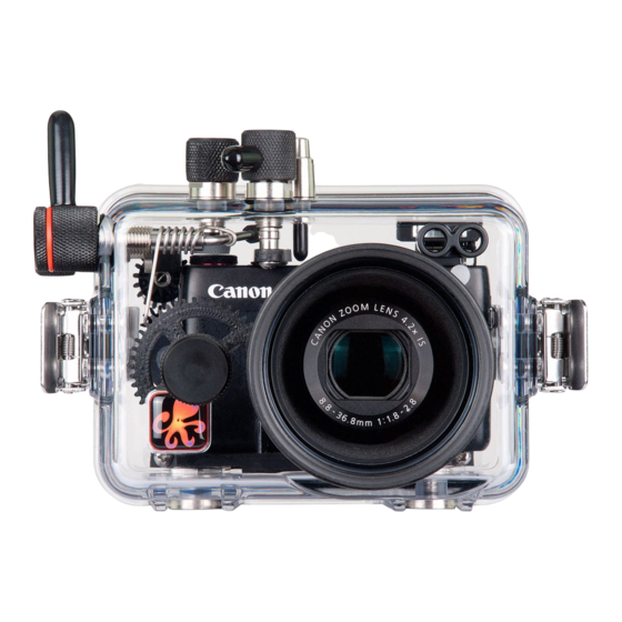
D igi tal H ou s i n g
I n s t r u c t i o n M a n u a l
6146.07 Canon Powershot G7 X
Thank you for your purchase of Ikelite equipment. Please read this
instruction manual completely before attempting to operate or dive
with this product. Please refer to the back page of this manual to
register your Ikelite product.
Advertisement
Table of Contents

Subscribe to Our Youtube Channel
Related Manuals for Ikelite 6146.07


Summary of Contents for Ikelite 6146.07
- Page 1 I n s t r u c t i o n M a n u a l 6146.07 Canon Powershot G7 X Thank you for your purchase of Ikelite equipment. Please read this instruction manual completely before attempting to operate or dive with this product.
-
Page 2: Table Of Contents
Table of Contents Preparation ..............P. 3 Specifications ..............P. 4 What’s in the Box ............P. 4 Parts of the Housing - Front View ........P. 5 Parts of the Housing - Back View ........P. 6 Housing and Camera Setup ........P. 7 STEP 1 - Initial Camera Setup ........P. 7, 8 STEP 2 - Opening the Housing ........P. -
Page 3: Preparation
Table of Contents continued Maintenance ..............P. 21 - 25 Photo Tips ..............P. 26 Troubleshooting ............P. 27 - 29 Spare Parts ..............P. 29 Customer Support ............P. 30 Limited Warranty ............P. 30 Returning Products for Service ........P. 31 Product Registration ..........Back Page Preparation This product has been water pressure tested at the factory and is depth rated to 200 ft (60m). -
Page 4: Specifications
Specifications (no camera installed) Depth Rating......200 ft (60m) Controls ........All important camera functions accessed ..........except Flash Up Switch and Mobile Device ..........Connection Button Buoyancy ......Near neutral buoyancy in freshwater Housing Weight ....2.6 lb (1.18kg) Strobe Connection ....Fiber Optic Ports Use Built-in Flash....Yes Optional Tray Mounting ..12-24 thread external tray mounting with 3 in ..........(76 mm) spacing Main O-Ring ......0109... -
Page 5: Parts Of The Housing - Front View
Parts of the Housing - Front View Housing controls are provided for all camera functions except the flash up switch and mobile device connection button. The built-in camera flash must be extended BEFORE placing the camera in the housing. Zoom Lever Shutter Mode Dial Release... -
Page 6: Parts Of The Housing - Back View
Parts of the Housing - Back View RING FUNC 9 10 MENU 6. FUNC./SET Button 1. Control Dial Ring Function / Single Erase Flash Mode / Right Button DISP. Display / Down Button Movie Button Drive Mode / Up Button Playback Button 10. -
Page 7: Housing And Camera Setup
Housing and Camera Setup STEP 1 - Initial Camera Setup (before placing camera in housing) Setup your camera for underwater use and then adjust your settings once underwater. Set camera mode switch to “Av” Aperture Priority. MENU: Set AF Frame to “1-point”, AF Frame Size to “Normal.” Set Digital Zoom to “Off.”... -
Page 8: Step 2 - Opening The Housing
STEP 1 - Initial Camera Setup continued Set ND Filter to “Off” and Still Image Aspect Ratio to “4:3.” Set Image recording type to “JPEG” and compression to “L” Superfine. Set Drive Mode to “Single Shot ” Set Movie Quality to “FHD60P.” RAISE FLASH and set to forced ON (flash always fires) “... -
Page 9: Step 3 - Attach Camera To Mounting Tray
STEP 3 - Attach Camera to Mounting Tray 1. The Mounting Tray for the camera is secured to the housing back. Position the camera on the Mounting Tray. 2. Using a coin or screwdriver (preferred), secure the camera with the Mounting Tray Bolt which threads into the camera’s tripod socket, Diagram B, below. -
Page 10: Step 4 - Attach The Control Ring Gear
STEP 4 - Attach the Control Ring Gear The supplied Control Ring Gear is attached to the camera control ring by 3 small nylon hex head Set Screws. Place the Control Ring Gear over the camera’s control ring before installing the camera in the housing. The Gear is a “press fit”... -
Page 11: Step 5 - Installing Camera In Housing
STEP 5 - Installing Camera in the Housing 1. Pull out on each housing control until it stops. This will get the controls out of the way for installation of the camera. 2. Remove camera lanyard from camera if attached. 3. -
Page 12: Step 7 - Final Check
STEP 7 - Final Check The clear housing permits instant visual inspection of the camera and sealing surfaces as well as complete monitoring of controls and camera LCD screens. This housing has been factory water pressure tested to 200 ft (60m). Once the housing is closed, recheck the o-ring seal. -
Page 13: Built-In Flash And Strobe Use
Alternatively, two ports are provided on the front of the housing for the connection of up to two Ikelite, SEA&SEA, or Olympus type fiber optic cords. -
Page 14: Using The Camera's Built-In Flash
Using the Camera’s Built-in Flash If you are shooting with the camera’s built-in flash and the camera lens is set to the widest angle setting, you may need to zoom the lens slightly or a dark area may appear in a lower corner of close-up photographs. The lens port may block some of the light. -
Page 15: Diffuser Purpose
Diffuser Purpose When using the built-in camera flash and shooting close-up photographs, the lens port on the housing can block a portion of the light from the built-in camera flash. This can result in a shadow in a lower corner of the picture frame. -
Page 16: Entering The Water
The color filters are for available light use only. Not recommended when using external strobes. Optional Tray with Release Handle 9523.61 The optional aluminum tray with release handle comes with the necessary hardware to mount to your Ikelite housing. To attach, see page 17. - Page 17 Use the mounting procedure below to attach either a single or dual tray to an Ikelite Compact or ULTRAcompact housing. MADE IN USA Attach Optional Tray with Release Handle(s) to Housing 1. Place the housing upside...
- Page 18 The AF35 Strobe Package is available to support your housing along with a full range of accessories. Please visit www.ikelite.com to see additional information regarding this and other strobe package options.
- Page 19 We recommend the Ikelite W30 Wide Angle Lens or INON UWL-H100 Wide Angle Lens for excellent edge sharpness with minimal vignetting (dark shadows in the corners of the image). Vignetting may be eliminated by either zooming slightly or cropping the image in post-production.
-
Page 20: Additional Accessories
Additional Accessories 2602.3 Quick Release Handle Kit for GoPro Gamma LED Focus/Flashlight A full range of accessories are available to support your housing. Please visit www.ikelite.com to see the most current information about recommended accessories for your housing. -
Page 21: Maintenance
Do not use alcohol or window cleaner on the Lens Port. Lubricant Ikelite provides silicone lubricant with the housing. We recommend you use only Ikelite lubricant on Ikelite products. Other brands may cause the main housing o-ring to swell and not seal properly, or the plastic components to crack. - Page 22 Housing Maintenance Your Ikelite Digital Housing should be given the same care and attention as your other photographic equipment. In addition to normal maintenance, we recommend that the housing be returned to Ikelite periodically to be checked and water pressure tested.
- Page 23 Control Maintenance Ikelite controls are designed to provide years of reliable service with minimal maintenance. Push button controls normally require no maintenance other than rinsing in freshwater after saltwater use. Depress each push button in fresh water several times to eliminate trapped saltwater. If a push button control becomes difficult to push or if it sticks when depressed, soak the housing in luke warm freshwater.
- Page 24 Lightly lubricate the shaft, then move the shaft in and out several times. This will lubricate the x-ring in the Ikelite control gland. This should be done before using the housing after a prolonged storage period, or once a week when the housing is in constant use.
- Page 25 Diagram C Lubricate end of shaft Set screw (hex head before reinserting into wrench required) gland Housing Control Shaft Knob O-rings Control Tighten set screw down against this Gland flat area when replacing the knob. Diagram D Lubricate shaft Housing Pull out knob to expose shaft Diagram E...
-
Page 26: Photo Tips
Photo Tips The number one rule in underwater photography is to eliminate as much water between the camera and subject as possible. Get as close as you can to the subject, then use the zoom. If you are using flash for still photos, subjects beyond 6 ft (1.8m) will not have much color regardless of strobe power. -
Page 27: Troubleshooting
If still sticky, see the Control Maintenance section, page 24. - Return housing to Ikelite for routine maintenance. Image is - Check that the built-in flash or external strobe is over/underexposed, firing when taking a picture. - Page 28 Place one or two new packs in your housing before each day of diving. - If moisture or water droplets are present around the controls or sealing areas, return the housing to Ikelite for evaluation. - Clean the main housing o-ring and sealing surface of the housing.
-
Page 29: Spare Parts
- Look for hair, dirt, or foreign debris crossing the o-ring seal. - Reassemble the housing without a camera installed and immerse in water. - Return housing to Ikelite for evaluation. Pictures are too blue - Use custom (manual) white balance. Reset for or too green each working depth or when attaching a color correcting filter to the camera lens. -
Page 30: Customer Support
This Ikelite product is warranted against any manufacturing defects for a period of one (1) year from the original date of purchase. Defective products should be returned to Ikelite postage paid. Ikelite will, at its sole discretion, repair or replace such products, and will return to customer postage paid. -
Page 31: Returning Products For Service
Returning Products For Service Ikelite is most interested in performing any service to ensure that all products perform as intended. Evidence of purchase date must be provided to obtain warranty service. No prior authorization is required. You may return directly to us or through your dealer. -
Page 32: Product Registration
Product Registration Please go to www.ikelite.com to register your Ikelite housing within 15 days of purchase. Ikelite Underwater Systems 50 West 33rd Street Indianapolis, IN 46208 USA www.ikelite.com © 2014 Ikelite Underwater Systems 6146.07_Canon_G7X_1-1114...
Need help?
Do you have a question about the 6146.07 and is the answer not in the manual?
Questions and answers