Table of Contents
Advertisement
Quick Links
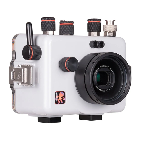
Underwater Housing for Canon Powershot G5X
Product Number 6146.05
I n s t r u c t i o n M a n u a l
Thank you for your purchase of Ikelite equipment. Please read this instruction
manual completely before attempting to operate or dive with this product.
Please refer to the back page of this manual to register your Ikelite product.
Advertisement
Table of Contents

Related Manuals for Ikelite 6146.05


Summary of Contents for Ikelite 6146.05
- Page 1 I n s t r u c t i o n M a n u a l Thank you for your purchase of Ikelite equipment. Please read this instruction manual completely before attempting to operate or dive with this product. Please refer to the back page of this manual to register your Ikelite product.
-
Page 2: Table Of Contents
Using Non-Ikelite or Ikelite Non-DS-series Strobes....P. 13 Manual Flash Operation with Ikelite DS-series Strobes ..P. 14 Attach Ikelite Sync Cord to the Housing and Strobe ....P. 15 Using Fiber Optic Strobes ............P. 16 Using the Camera’s Built-in Flash ...........P. 16 Deflector Installation and Removal ..........P. -
Page 3: Preparation
Table of Contents - continued Zoom Control Use ..............P. 17 RECOMMENDED ACCESSORIES and ATTACHMENTS ..P. 18 SPARE PARTS ...............P. 20 MAINTENANCE ..............P. 20 Lens Port .................P. 20 O-ring Storage .................P. 20 Lubricant ..................P. 21 Housing Maintenance ..............P. 21 - 22 Control Maintenance ...............P. -
Page 4: Specifications - No Camera Installed
..........dial and Mobile Device Connection Buoyancy ....... Slightly negative in freshwater Depth Rating ......200 ft (60 m) Strobe Connection ....Ikelite ICS-5 5pin electrical bulkhead or ..........Fiber Optic housing ports Use Built-in Flash ....Yes Main O-ring ......0110 Housing Dimensions ..... -
Page 5: Parts Of The Housing - Front View
Parts of the Housing - Front View Zoom Fiber Optic Bulkhead Lever Ports Connector Exp. Shutter Comp. ON/OFF Mode Dial Button Dial Front Dial 1/4-20 External Tray Mounts... -
Page 6: Parts Of The Housing - Back View
Parts of the Housing - Back View MOVIE INFO MENU 7. Q-Set / Set Button 1. Control Dial 2. Movie Button Flash / Right Button INFO / Down Button Single-image Erase Button AF Frame Selector Playback Button 11. MENU Button Drive Mode / Up Button MF / Macro / Left Button... -
Page 7: Housing And Camera Setup Steps
HOUSING and CAMERA SETUP STEPS Step 1 - Camera Setup Set Mode Dial to “Av” or “M.” Set ISO to “200.” IMPORTANT: In Display Settings, set Display Control to “Manual.” This option turns off eye-piece automation and must be set, otherwise, the camera will sense the housing back and shut off the LCD screen in favor of the optical viewfinder. -
Page 8: Step 2 - Opening The Housing
Step 2 - Opening the Housing Lid Snaps have a Lock. 1. Push Lid Snap Locks forward and lift as shown. Open opposing Lid Snaps simultaneously. Keep pressure on the Lid Snaps so they do not fly open quickly. Some Lid Snaps have a lot of spring tension once they go over center, so keep a firm grip on each Lid Snap. - Page 9 Step 3 - Install Camera in Housing - continued Diagram A Pull to Remove Mounting Plate Mounting Tray 4. Using a coin or flathead screwdriver (preferred), secure the camera Mounting Tray to the camera tripod mount, Diagram B. Tighten camera firmly to Diagram B avoid movement on tray.
-
Page 10: Step 4 - Attach Hotshoe (If Not Using Built-In Flash)
Step 4 - Attach Hotshoe (if not using built-in flash) When connecting an external strobe to the housing bulkhead, slide the hotshoe into the top camera mount until it stops. Hotshoe must be all the way forward in the camera mount to assure a good electrical connection with a strobe, Diagram C, below. -
Page 11: Step 5 - Closing The Housing
Step 5 - Closing the Housing Lid Hook 1. Place housing face down in your lap. Check to see that there is an o-ring on the housing back, and that it is clean and in its proper location. 2. Guide the back onto the Even gap on housing front. -
Page 12: Step 7 - Entering The Water
Step 7 - Entering the Water Before entering the water, turn the camera on and operate each of the housing controls to get a feel for using the camera in the housing. As soon as you enter the water, take a moment and check to see that the housing is properly sealed. -
Page 13: Strobe Compatibility And Use
The Conversion Circuitry is automatically disabled when used with a Non-Ikelite or Non-DS-series Strobe. These Strobes can be used in their manual mode utilizing any power settings provided on the Strobe. To attach a Non-Ikelite strobe to the housing, go to ikelite.com to select the proper cord. -
Page 14: Manual Flash Operation With Ikelite Ds-Series Strobes
Manual Flash Operation with Ikelite DS-Series Strobes We recommend placing the strobe in TTL mode (or a manual fractional power setting), so you can see both preflashes. Set camera to “Av” or “Tv” shooting mode. Press the FEL control 4 times within 4 seconds. -
Page 15: Attach Ikelite Sync Cord To The Housing And Strobe
The Ikelite Housing and Strobe Bulkheads are designed to accept sync cords with Ikelite 5 pin connector fittings. 1. Lightly lubricate the Sync Cord O-rings. Use ONLY Ikelite lubricant (supplied with housing). Other lubricants may cause the o-rings to swell and seal improperly. -
Page 16: Using Fiber Optic Strobes
Using Fiber Optic Strobes Attach Fiber Optic Cord(s) to the housing Fiber Optic Port(s), page 5, directly above the housing port. Make sure the housing deflector is installed in the housing (see Deflector Installation and Removal below). NOTE: Camera built-in flash must be extended and hotshoe disconnected BEFORE closing housing. -
Page 17: Diffuser Installation And Removal
Diffuser Installation and Removal The included Diffuser should only be used when shooting with the built-in camera flash. Always remove the Deflector before using ONLY the built-in camera flash with the Diffuser. To install the Diffuser, Diagram G, push the “Cut-out Section” into the external Port Groove until it stops as shown, Diagram H. -
Page 18: Recommended Accessories And Attachments
Optional Tray + Release Handle 9523.63 The optional aluminum tray with release handle comes with the necessary hardware to mount to your Ikelite housing. To attach, see page 19. MADE IN USA Optional Tray + Dual Handles 9523.64 Attaching an optional Tray + Dual Handles will add stability and gripping point(s) for comfortable use of the housing. - Page 19 The WD-3 simply slides over the standard port of the your Ikelite housing. The WD-3 can be removed and replaced underwater so there is no limit to the camera’s zoom or macro capabilities. Approximately 3/4 of the camera’s zoom range can be used with the dome in place (varies by camera model).
-
Page 20: Spare Parts
O-ring Storage When storing the housing, remove the main housing o-ring. Lightly lubricate the o-ring until it appears shiny and place in a small resealable plastic bag. Use only Ikelite lubricant. Place the bag inside the housing and store until needed. -
Page 21: Lubricant
Lubricant Ikelite provides silicone lubricant with the housing. We recommend you use only Ikelite lubricant on Ikelite products. Other brands may cause the main housing o-ring to swell and not seal properly. Use only enough lubricant to lightly cover the main housing o-ring or lubricate a sticky control. -
Page 22: Control Maintenance
Place the plastic bag with o-ring inside the housing for safe keeping. If removing a housing push button, Do Not re-use the E-clip. Contact Ikelite for replacement E-clips (part 0319.12). - Page 23 Check the control for watertightness. Apply Ikelite Lube Here Ikelite controls are designed to provide years of reliable service with minimal maintenance. In the unlikely event one of the control shafts sticks or becomes difficult to operate, you can remove the control from the housing and lubricate it, or return the housing to Ikelite for maintenance.
- Page 24 To lubricate the control, gently pull on the knob until the stainless steel shaft is exposed. Lightly lubricate the shaft, then move the shaft in and out several times. This will lubricate the x-ring in the Ikelite control gland. This should be done before using the housing after a prolonged storage period, or once a week when the housing is in constant use.
- Page 25 Control Maintenance - continued Loosen Set Screw Lubricate end of shaft (Hex Head Wrench Required) before reinserting into Diagram J gland Knob Control Shaft O-rings Control Gland Tighten set screw down against this flat area when replacing the knob Housing Lubricate Shaft Diagram K Housing...
-
Page 26: Photo Tips
PHOTO TIPS The number one rule in underwater photography is to eliminate as much water between the camera and subject as possible. Get as close as you can to the subject, then use the zoom. If you are using flash for still photos, subjects beyond 6 ft (1.8 m) will not have much color regardless of strobe power. -
Page 27: Troubleshooting
If still sticky, see the Control Maintenance section, pages 23-26. - Return housing to Ikelite for routine maintenance. Image is over/ - Check that the built-in flash or external strobe is underexposed, firing when taking a picture. - Page 28 Place one or two new packs in your housing before each day of diving. - If moisture or water droplets are present around the controls or sealing areas, return the housing to Ikelite for evaluation. - Clean the main housing o-ring and sealing surface of the housing...
- Page 29 Problem Solution Pictures are too - Use custom (manual) white balance. Reset for blue or too green each working depth or when attaching a color correcting filter to the camera lens. - Add an external strobe. - Move in closer to your subject when taking a picture.
-
Page 30: Customer Support
This Ikelite product is warranted against any manufacturing defects for a period of one (1) year from the original date of purchase. Defective products should be returned to Ikelite postage paid. Ikelite will, at its sole discretion, repair or replace such products, and will return to customer postage paid. -
Page 31: Returning Products For Service
RETURNING PRODUCTS FOR SERVICE Ikelite is most interested in performing any service to ensure that all products perform as intended. Evidence of purchase date must be provided to obtain warranty service. No prior authorization is required. You may return directly to us or through your dealer. -
Page 32: Product Registration
PRODUCT REGISTRATION Please go to ikelite.com to register your Ikelite housing within 15 days of purchase. Ikelite Underwater Systems 50 West 33rd Street Indianapolis, IN 46208 USA ikelite.com © 2016 Ikelite Underwater Systems 6146.05_Canon_G5X_1-0116...
Need help?
Do you have a question about the 6146.05 and is the answer not in the manual?
Questions and answers