Advertisement
Quick Links
ADVANCED MODEL ROCKET
Assembly and Operation Instructions
Assembly and Operation Instructions
BEFORE YOU BEGIN
• Study the illustrations and sequence of assembly. The
sequence of assembly is important. Review the parts list
and become familiar with all parts before assembly. If any
parts are missing or damaged, contact RCS at 1-435-865-
7100 or email at warranty@aerotech-rocketry.com.
• DO NOT MODIFY THE DESIGN OF THIS ROCKET .
Changes to the design of the rocket such as, but not limited
to, reducing the fin size, shortening the body tube, or modi-
fying the motor tube assembly can adversely affect the flight
stability of the rocket and may void this products warranty.
• Only use AeroTech composite single-use model rocket
motors and RMS™ Reloadable Motor System™ reload kits
in this model rocket. See our Motor Matrix for recommended
AeroTech propulsion.
Read and follow the Model Rocket Safety Code
of the National Association of Rocketry (NAR
and comply with all federal, state and local laws
in all activities with model rockets.
PARTS LIST
Qty
Description
1
Thrust Ring
(7/16" Long)
1
Thrust Ring Flange
(1/16" Thick)
1
Motor Tube
(1 1/8" OD x 17-3/4" long)
1
Motor Hook
2
FIN-LOK Rings (3 Fin)
3
Centering Rings
(3.896" OD)
3
Fins
1
Cooling Mesh
1
Ejection Gas Baffle
2
Screw Eyes
1
Shock Cord
(5/8" x 18')
1
Econojet Motor Spacer
1
Lower Body Tube-Slotted
1
Upper Body Tube
(3.990" OD x 19" Long)
1
Bulkhead Disk
(3.896" OD)
1
Tube Coupler
(3.886" OD x 6" Long)
2
Launch Lugs
1
Nose Cone
1
42" Nylon Parachute
1
Decal Sheet
1
Instruction Sheet
ADDITIONAL MATERIALS AND TOOLS REQUIRED
• 12" ruler (with 1/16" resolution)
• Medium viscosity cyanoacrylate (cyano') cement OR
• 5 to 15 minute cure epoxy
• Accelerator for cyanoacrylate cement
• Hobby knife with #11 blade
• 1/8" dia. wood dowel at least 12" long
• #240 grit sandpaper
Part #
(14010)
(14011)
(12918)
(19001)
(19343)
(14029)
(11715)
(19011)
(19030)
(19015)
(17201)
(14003)
(14023)
(3.990" OD x 23" Long)
(14019)
(14009)
(14008)
(19035)
(11401)
(13042)
(18021)
(19921)
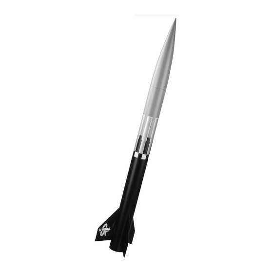
COMPLETED
G-FORCE™
ADVANCED
MODEL
ROCKET
)
®
1
19921-0100
Rev. 8/12/04
Read And
Follow All
Instructions
Designed By
Ed LaCroix
Advertisement

Related Manuals for Aerotech G-Force


Summary of Contents for Aerotech G-Force
- Page 1 • Only use AeroTech composite single-use model rocket motors and RMS™ Reloadable Motor System™ reload kits in this model rocket. See our Motor Matrix for recommended AeroTech propulsion.
- Page 2 2" 51 mm 3" LOCATION 1/4" 1/2" 76 mm 4-1/16" 13 mm GUIDE 6 mm 103 mm 4-5/8" 117 mm Front Edge of Back Edge Of Tube Coupler Motor Back Edge Of Back FIN- Front FIN-LOK™ Marking Guide Hook Motor Tube Ring LOK™...
- Page 3 DO NOT apply cement to the back edge of the the height of the ribs on either side of the FIN-LOK™ tab back FIN-LOK™ ring. (NOTE: The unique AEROTECH may need to be reduced. Make any adjustments with a FIN-LOK™...
- Page 4 LOWER BODY AND FIN ASSEMBLY Launch Lug Slots FIN-LOK™ Motor Tube Body Assembly Tube Slot Launch Lugs 1. Using a hobby knife, carefully remove any body tube snug against the body tube.) material that may still be attached to the pre-cut slots in the body tube.
-
Page 5: Vehicle Data
Motor Mount: 29mm Recovery System: 42" Parachute DECAL INSTRUCTIONS Reference the photograph of the completed G-Force bowl with warm water and put one or two drops of a rocket on the first page of these instructions for proper dishwashing detergent into the water. -
Page 6: Operation Instructions
The tube coupler assembly 5. LAUNCH PAD: Your AEROTECH rocket must be flown from a launch pad should slide freely into the lower body assembly. (NOTE: Because your with a 1/4"(6.4mm) diameter metal launch rod at least 36"(0.9m) long (as...
Need help?
Do you have a question about the G-Force and is the answer not in the manual?
Questions and answers