Advertisement
Quick Links
LC87F1MADG1AGEVK
LC87F1M16A Evaluation
Board User's Manual
Summary
This document describes the specification of this product
"LC87F1MADG1AGEVK", and it uses the following
software.
Table 1. SUMMARY
Kind of Software
Microcontroller
LC87F1M16A Version 0x1000
Application for PC
LC87F1MADG1AGEVK_Application.exe
Driver
LC87F1MADG1AGEVK_driver.inf
Content
Evaluation Board (USB−DG1−1Ma1−EVK):
USB-mini Cable:
Connector (FSS−43085−05 HIROSUGI−KEIKI):
CD-ROM*:
* Please use the included CD-ROM for the documentations, driver
for this software, application software, and sample application
software.
© Semiconductor Components Industries, LLC, 2014
February, 2014 − Rev. 3
Name of the Software
EVAL BOARD USER'S MANUAL
About Application
Required OS:
Windows XP or later
Profile Needed: .NET Framework4 Client Profile
Summary of the Product
This product is for data receiving/transmitting by
changing the various input/output formats listed below from
PC to device and vice versa.
•
2
I
C
•
SPI
•
PWM
•
Digital Input/Output (GPIO)
•
1
ADC
1
1
1
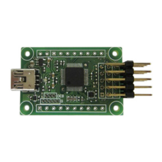
Figure 1. LC87F1M16A
1
http://onsemi.com
Publication Order Number:
EVBUM2170/D
Advertisement

Subscribe to Our Youtube Channel
Related Manuals for ON Semiconductor LC87F1M16A


Summary of Contents for ON Semiconductor LC87F1M16A
- Page 1 This product is for data receiving/transmitting by Kind of Software Name of the Software changing the various input/output formats listed below from PC to device and vice versa. Microcontroller LC87F1M16A Version 0x1000 • Application for PC LC87F1MADG1AGEVK_Application.exe • Driver LC87F1MADG1AGEVK_driver.inf •...
- Page 2 LC87F1MADG1AGEVK COMPOSITION OF THIS PRODUCT Figure 2. Composition http://onsemi.com...
- Page 3 LC87F1MADG1AGEVK CONNECTION DIAGRAM WHEN USE * PC, Device and Interface cable is not included. Figure 3. Connection Diagram http://onsemi.com...
- Page 4 LC87F1MADG1AGEVK SUMMARY OF THE PINS ON THE PRODUCT Extension Terminal 1 USB Mini Cable Terminal Interface Cable Terminal Extension Terminal 2 PWM1 PWM0 GPIO7 GPIO3 GPIO6 GPIO2 GPIO5 GPIO1 GPIO4 GPIO0 Figure 4. Summary of the Pins USB-Mini Cable Terminal USB2.0 compliant Initial state of the LED is OFF.
- Page 5 LC87F1MADG1AGEVK Table 2. INTERFACE CABLE TERMINAL Name State of the Possible Setting of the Pin of the Terminal I/O Setting Input Voltage Range Max. Output Current − Refer to the Micro’s Catalogue 0 to 3.3 V Refer to the Micro’s Catalogue 0 to 3.3 V Refer to the Micro’s Catalogue −...
- Page 6 LC87F1MADG1AGEVK HOW TO USE THIS PRODUCT Basic steps of the operation • Connect the PC and this product via USB-Mini cable Figure 5. Connection via USB-Mini Cable • After connected, below window appears automatically • Install the driver in PC (In case of Windows XP 32bit) Figure 6.
- Page 7 LC87F1MADG1AGEVK Figure 7. Driver Installation − Step 2 Figure 8. Driver Installation − Step 3 http://onsemi.com...
- Page 8 LC87F1MADG1AGEVK Figure 9. Driver Installation − Step 4 • LED will light-up if the installation is successful • Connect the device and the interface cable of this product • Start the application named “LC87F1MADG1AGEVK_Application.exe” Figure 10. Device Connection http://onsemi.com...
- Page 9 SPECIFICATION OF THE INPUT/OUTPUT TYPES C Communication 1. Summary: 3. Summary of the Communication: • SIO of LC87F1M16A microcontroller is used for Only Supports Single Master Mode • this communication… Only Supports Fast-mode (Bit Rate is 400 kbps) This communication format is based on •...
- Page 10 LC87F1MADG1AGEVK 4. Application Window: Figure 11. Application Window (I 1. Summary: CK: used as SCK of SPI SIO of LC87F1M16A microcontroller is used for GPIO:used as SS of SPI this communication… 3. Communication Summary: • This communication is based on “SPI Block Guide Only SupportsNormal Mode V4.01”...
- Page 11 LC87F1MADG1AGEVK Table 6. PWM0, 1 1. Summary: Frequency Duty Changeable Step Synchronous×2ch, asynchronous×2ch, total of 4ch 750.0 [kHz] 16 steps can be output as PWM. 375.0 [kHz] 32 steps Using filter, it is capable of small DC voltage step 250.0 [kHz] 48 steps control.
- Page 12 LC87F1MADG1AGEVK Digital Input/Output (GPIO) 1. Summary: Open/Pull-up when input. Capable of selecting 3.3 V or 0 V of input/output GPIO12: Select Low/High when output, and select Open/Pull-up when input. 2. Pins to Be Used: GPIO13: Select Low/High when output, and select GPIO0: Select Low/High when output, and select Open/Pull-up when input.
- Page 13 LC87F1MADG1AGEVK 1. Summary: 3. Setting: Converts the voltage to the value − 8bitAD/12bitAD − Selection of conversion time 2. Pins to be used: GPIO0: ADC port 0 8bitAD 12bitAD GPIO1: ADC port 1 Conversion Time Conversion Time Unit GPIO2: ADC port 2 GPIO3: ADC port 3 GPIO4: ADC port 4 10.8...
- Page 14 LC87F1MADG1AGEVK CIRCUIT DIAGRAM http://onsemi.com...
-
Page 15: Parts List
− − − ±0.07% Ceramic 12 Mhz, 33 pF Murata CSTCE12M0GH5L Resonator Zener Diode 6.2 V, 200 mW SOD−523 ON Semiconductor MM5Z6V2ST1G Diode SOD−323−2 ON Semiconductor MMDL6050T1G Micro Controller SQFP48 ON Semiconductor LC87F1M16AF5ZA0WA−6H (7 × 7) LDO Regulator 3.3 V, 500 mA... - Page 16 LC87F1MADG1AGEVK PATTERN DIAGRAM − FRONT http://onsemi.com...
- Page 17 LC87F1MADG1AGEVK PATTERN DIAGRAM − BACK http://onsemi.com...
- Page 18 LC87F1MADG1AGEVK PATTERN DIAGRAM − LOCATION OF THE PARTS http://onsemi.com...
- Page 19 LC87F1MADG1AGEVK IF YOU THINK IT IS BROKEN Application Does Not Start Check start. Check the LED is lit up. Check the device manager that is shows like a red circle shown above. (In case of Windows XP) Check if the driver is installed.
- Page 20 PUBLICATION ORDERING INFORMATION LITERATURE FULFILLMENT: N. American Technical Support: 800−282−9855 Toll Free ON Semiconductor Website: www.onsemi.com Literature Distribution Center for ON Semiconductor USA/Canada Order Literature: http://www.onsemi.com/orderlit P.O. Box 5163, Denver, Colorado 80217 USA Europe, Middle East and Africa Technical Support: Phone: 303−675−2175 or 800−344−3860 Toll Free USA/Canada...
Need help?
Do you have a question about the LC87F1M16A and is the answer not in the manual?
Questions and answers