Table of Contents
Advertisement
ALINCO, INC.
Yodoyabashi Dai-bldg 13F
4-4-9 Koraibashi, Chuo-ku, Osaka 541-0043 Japan
Phone: +81-6-7636-2362 Fax: +81-6-6208-3802
http://www.alinco.com
E-mail:export@alinco.co.jp
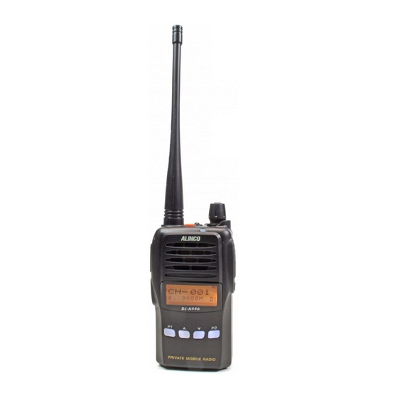
UHF FM transceiver 8 PMR446 channels.
Use of this device is authorized in all EU and EFTA member
states (CH/ICE/LI/NOR).
Copyright Alinco, Inc. PS0664/FNEG-NI
Printed in China
Advertisement
Table of Contents

Related Manuals for Alinco DJ-A446


Summary of Contents for Alinco DJ-A446
- Page 1 Yodoyabashi Dai-bldg 13F 4-4-9 Koraibashi, Chuo-ku, Osaka 541-0043 Japan Phone: +81-6-7636-2362 Fax: +81-6-6208-3802 http://www.alinco.com E-mail:export@alinco.co.jp UHF FM transceiver 8 PMR446 channels. Use of this device is authorized in all EU and EFTA member states (CH/ICE/LI/NOR). Copyright Alinco, Inc. PS0664/FNEG-NI Printed in China...
-
Page 2: Instruction Manual
DJ-A446 Instruction Manual Thank you for purchashing your new Alinco transceiver.Please read this manual carefully before using the product to ensure full performance, and keep this manual for future reference as it contains information on after-sales service. In case addendum or errata sheets are included with this product,please read... -
Page 4: Before Transmitting
(which is higher than10 kA.). Note also that no car provides adequate protection of its passengers or drivers against lightning as well. Therefore, Alinco will not take responsibility for any danger associated with using its hand-held radios outdoor or inside the car during lightning. - Page 5 Alinco accessories and the radio has not been disassembled by the customer. The factory has tested and made the equipment compatible to IP54 certification during engineering.
- Page 6 Features ■ Li-Ion battery pack and stand-charger as standard accessories ■ FM broadcasting 76-108MHz receiver built-in ■ Sub-tone (CTCSS/DCS) Encode/ Decode and DTMF/ANI ■ Inversion Scramble(Analog encryption) Conformity Symbols Tested to comply MIL-STD-810G -Shock: Method 514.6/I,IV -Vibration: Method 516.6/I...
-
Page 7: Environment And Condition Of Use
Alert Environment and condition of use Use of this product may be prohibited or illegal outside of your country. Be informed in advance when you travel. It is recommended that you check local traffic regulations regarding the use of a radio equipment while driving. -
Page 8: Handling This Product
The manufacturer declines any responsibilities against loss of life and property due to a failure of this product when used with or as a part of a device made by third parties. Use of third party accessory may result in damage to this product. It will void our warranty for repair. Handling this product Be sure to reduce the audio output level to minimum before using an earphone or a headset. -
Page 9: In Case Of Emergency
Securely plug the adapter into the wall outlet. Insecure installation may result in short-circuit, electronic shock and/or fire. Do not use the adapter if the plug or socket contacts are dirty. Overheating and/or short-circuiting may result in fire, electric shock and/or damage to the product. In case of emergency In case of the following situation(s), please turn off the product, switch off the source of power, then remove or unplug the power-cord. -
Page 10: About Transceiver
Alert Environment and condition of use Do not use the product in proximity to a TV or a radio. It may cause interference or receive interference. Do not install in a humid, dusty or insufficiently ventilated place. It may result in electric shock, fire and/or malfunction. - Page 11 Use a clean, dry cloth to wipe off dirt and condensation from the surface of the product. Never use thinner or benzene for cleaning. Check with your local waste officials for details on recycling or proper disposal of the electronics product, battery-packs and accessories in your area.
-
Page 12: Table Of Contents
CONTENTS STANDARD ACCESSORIES/OPTIONAL ACCESSORIES ..........1 Standard Accessories .........................1 BATTERY INFORMATION ....................2 Charging Operation ..........................2 Battery Charger Type .......................... 2 Notice for Charging Battery ......................... 2 How to Charge the battery pack ......................4 INSTALLATION & CONNECTION ..................6 How to Store the Battery ........................ - Page 13 CONTENTS Power On and off ..........................12 Adjusting Audio output level ........................ 12 Emergency Alarm Function........................13 Adjusting Channel ..........................13 Side Key[PF1](Jacklight Switch) ......................13 Side Key[PF2](Keypad lock) ....................... 13 Squelch Off ............................13 Receiving ............................14 Transmitting ............................14 Resetting .............................
- Page 14 CONTENTS AUXILIARY FUNCTIONSSTARTING TAKES ..............19 Key programming..........................19 TECHNICAL SPECIFICATIONS ..................20 ATTACHED CHART ......................23 Channel Frequency Chart ........................23 CTCSS Frequency Chart ........................23 1024 groups DCS frequency chart ..................... 24 Professional FM Transceiver...
-
Page 15: Standard Accessories/Optional Accessories
STANDARD ACCESSORIES/OPTIONAL ACCESSORIES Standard Accessories Belt Clip Battery Charger AC Adaptor Instruction Hand Strap Manual NOTE: Accessories may differ depending on the version you have purchased. Please contact your local dealer for details of standard accessories and the warranty-policy before purchase. Professional FM Transceiver... -
Page 16: Battery Information
Battery Charger Type Please use Alinco's designated charger, other models may cause explosion and injury. After installing the battery, when the radio displays low battery, please charge the battery. - Page 17 BATTERY INFORMATION Caution • Risk of explosion, generation of heat or leak of chemicals inside if the battery is replaced by an incorrect type or reverse polarity. Use always the recommended types of batteries in this manual only. • The battery pack isn't fully charged when shipped. It must be charged before use. •...
-
Page 18: How To Charge The Battery Pack
BATTERY INFORMATION How to Charge the battery pack 1.Plug the AC adaptor into the AC outlet, then plug into the DC jack, the indicator lights orange for 1 second and goes out---waits to charge. 2.Slide the battery or transceiver with battery into the charger;... - Page 19 BATTERY INFORMATION NOTE: ▲ Trouble means battery heating, short-circuit or charger malfunction. Remove the battery pack from the charger immediately and contact to your local dealer for services. ▲ The max trickle pre-charging time is 30 minutes. In case the red indicator continues to blink longer, please stop charging and consult with your local dealer for services.
-
Page 20: Installation & Connection
INSTALLATION & CONNECTION How to Store the Battery 1.The battery should be kept in the status of 50% discharge when storing. 2.Remove the battery pack from the radio and keep it in a cool, dry place. 3.Keep away from source of heat and direct sunlight. Note: Incorrect storage will damage both the battery pack and the radio. -
Page 21: Installing / Removing The Belt Clip
INSTALLATION & CONNECTION Installing / Removing the Belt Clip Installing the Belt Clip: 1. Put the belt clip on the back of the unit, and the screw clockwise until it stops. 2. Confirm that the belt clip is securely attached. * Tighten up the screw occasionally. -
Page 22: Installing The Hand Strap
INSTALLATION & CONNECTION NOTE: 1.To keep the radio dust and splash resistant, the cover must be closed properly with the original supplied cover. 2.The radio is not dust and splash resistant while using the optional accessory risking that the water may penetrate inside through the plug. -
Page 23: Getting Acquainted
GETTING ACQUAINTED LCD Display Following are the meaning of the icons and signs shown on the display. Some icons may not appear while operating this product due to pre-programming status by your dealer. Scramble (Encryption) CTCSS Battery Capacity Channel No. FM radio Keypad Lock Busy Channel... -
Page 24: Front Panel
GETTING ACQUAINTED Front Panel Emergency Alarm Antenna Jacklight Power/volume switch LED indicator, green light when receiving , red light when transmitting Speaker Microphone Up/Down adjusting key P1 key P2 key Short press: Tone/DCS squelch Short press: FM radio Long press: lnversion scrambling Long press: Squelch Level PRIVATE MOBILE RADIO Professional... -
Page 25: Side Panel
GETTING ACQUAINTED Side Panel PTT key Accessory and PC programming port PF1 key PF2 key Belt Clip Battery Left Panel Right Panel Professional FM Transceiver... -
Page 26: Basic Operations
BASIC OPERATIONS Power On and off Turn 【 POWER 】 / 【 VOLUME 】 dial clockwise to power on. Turn it counterclockwise to power off. Adjusting Audio output level Press PF2 key to monitor white noise to refer to the current audio level. Turn 【... -
Page 27: Emergency Alarm Function
BASIC OPERATIONS Emergency Alarm Function While Stand-by state, press this key for 3 seconds to enable the emergency alarm function. When activated the function, the radio will sound an alarm beep and start transmitting the alarm beep. Adjusting Channel Press key/ key to choose the desired channel. -
Page 28: Receiving
BASIC OPERATIONS Receiving Select the channel that you wish to operate. When a signal is received on the channel that you selected, and S-meter is displayed on the LCD, then the received signal can be heard. The RX indicator also lights green at this time. NOTE: Please be aware of the squelch level and selective-calling settings such as CTCSS and DCS as you may risk not hearing the receiving signal. -
Page 29: P1 Key Operations
DCS: 017N-765I, 232 codes, "N" stands for positive, "I" stands for inverse codes. Default is OFF. Press 【 PF2 】 key to confirm and exit. Inversion scrambling (Encryption) NOTE: This is an analog encryption and decoding is possible by using commonly available receivers. Alinco does not warranty the confidentiality of the communications. Professional FM Transceiver... -
Page 30: P2 Key Operations
BASIC OPERATIONS An analog voice inversion scrambler is equipped and such audio processing can offer an advanced confidentiality to your business communications. Lomg press the 【 PF2 】 key, Scramble is enabled. Repeat the operations to turn off. Turn On/ Off FM Radio receiver Short pressing 【... -
Page 31: Optional Accessories
OPTIONAL ACCESSORIES EBC-34 Belt Clip EBP-87 Li-ion Battery Pack (DC 7.4V 1500mAh) EBP-88 Li-ion Battery Pack (DC 7.4V 1700mAh) EDC-189 Li-ion Battery Charger EDC-191E AC Adaptor (220V) EME-56A Earphone Microphone EMS-76 Speaker microphone Professional FM Transceiver... -
Page 32: Recommended Installation Of Earphone Microphone
Recommended installation of earphone microphone Earphone Use a clip to fix with collar. Clip the PTT unit closer to your mouth. Carry the radio on the side or the back of your body, and the cable should go around the back as shown. Clamp the excessive length of cable at your waist. -
Page 33: Auxiliary Functionsstarting Takes
AUXILIARY FUNCTIONSSTARTING TAKES Key programming The 【 PF1 】 , 【 PF2 】 , 【 P1 】 and 【 P2 】 keys are programmable. NOTE: The keys can be programmed of long press and short press, if program of short press, the function will be activated when press the programmed key, if program of long press, the function will be activated when press and hold the key for programmed time. -
Page 34: Technical Specifications
TECHNICAL SPECIFICATIONS General Audio Response +1~-3dB(0.3~2.55KHz) Frequency Range 446.00625–446.09375 MHz Hum & Noise ≥45dB Channel Capacity 128 channels Audio Distortion ≤5% Operating Voltage 7.4V DC ±20% Audio Power 1000mW/10% More than 14 Hours (1500mAh), by Output Battery Life 5-5-90 work cycle Frequency Stability ±2.5ppm Transmitting Part(ETSI EN 300 086 Standard Test) - Page 35 TECHNICAL SPECIFICATIONS Problem Corrective Action A.The battery may be exhausting. Recharge or replace the battery. B.The battery may not be installed correctly. Remove the battery No power and install it again. C.The power switch is broken; send it to local dealers to repair. D.Battery life is end;...
-
Page 36: Trouble Shooting Guide
C.Earphone jack is broken, please contact with local dealers to repair. NOTE: Alinco guarantees the supply of minimum-necessary spare parts such as battery-packs, components and mechanical parts for at least 5 years after the production of this product is terminated except in case of accidents beyond control. -
Page 37: Attached Chart
ATTACHED CHART Channel Frequency Chart 446.00625 446.05625 446.01875 446.06875 446.03125 446.08125 446.04375 446.09375 CTCSS Frequency Chart 67.0 94.8 131.8 171.3 203.5 69.3 97.4 136.5 173.8 206.5 71.9 100.0 141.3 177.3 210.7 74.4 103.5 146.2 179.9 218.1 77.0 107.2 151.4 183.5 225.7 79.7 110.9... -
Page 38: 1024 Groups Dcs Frequency Chart
ATTACHED CHART 1024 groups DCS frequency chart Professional FM Transceiver... - Page 39 ATTACHED CHART Professional FM Transceiver...
- Page 40 ATTACHED CHART Professional FM Transceiver...
Need help?
Do you have a question about the DJ-A446 and is the answer not in the manual?
Questions and answers