
Related Manuals for Zeus Appollo Z10I3KD


Summary of Contents for Zeus Appollo Z10I3KD
- Page 1 User Manual V1.1 User Manual -Installation -Operation Z10I3KD Z10I4KD Z10I5KD Zeus Appollo Solar...
-
Page 3: Table Of Contents
Contents Notes on this manual ................................. 2 Scope of Validation ..............................2 Symbols Used ................................2 1.3 Target Group ..................................3 Preparation ..................................4 Safety Instructions ............................... 4 Explanations of Symbols on Inverter ........................... 6 Product Information ................................7 Overview ..................................7 Major Characteristics .............................. -
Page 4: Notes On This Manual
The main purpose of this User Manual is to provide instructions and detailed procedures for installing, operating, maintaining, and troubleshooting the following three types of Z10 Series Inverters: • Z10I3KD • Z10I4KD • Z10I5KD Please keep this user manual available at all times in case of emergency. -
Page 5: Target Group
NOTICE NOTICE indicates a situation that can result in property damage, if not avoided. 1.4 Target Group • Chapter 1, 2, 3, 4, 7, 8, 9, 10 and chapter 11 are provided for anyone who is intending to use a Z10 Series Grid-tied Solar Inverter. Before any further action is taken, the operators must first read all safety regulations and be aware of the potential danger when operating high-voltage devices. -
Page 6: Preparation
Preparation 2.1 Safety Instructions DANGER DANGER due to electrical shock and high voltage DO NOT touch the operating component of the inverter, it might result in burns or death. TO prevent risk of electric shock during installation and maintenance, please make sure that all AC and DC terminals are unplugged. - Page 7 NOTICE Public utility only The PV inverter is designed to feed AC power directly into the public utility power grid; do not connect the AC output of the device to any private AC equipment. CAUTION The PV inverter will become hot during operation; please don’t touch the heat sink or adjacent surface during or shortly after operation.
-
Page 8: Explanations Of Symbols On Inverter
Equipment with the CE mark fulfils the basic requirements of the Guidelines Governing Low-Voltage and Electromagnetic Compatibility. No unauthorized perforations or modifications Any unauthorized perforations or modifications are strictly forbidden, if any defect or damage (device/person) occurs, Zeus Appollo Solar will not accept any responsibility for it. -
Page 9: Product Information
Product Information 3.1 Overview • Industrial Layout Excellent Heat Elimination •... -
Page 10: Major Characteristics
Effective Shield For DC/AC/Communication Connections • 3.2 Major Characteristics The Z10 series inverter has the following characteristics which ensures that it delivers on the promise of “high efficiency, high reliability and having a high cost effective ratio” • An extensive DC input voltage and current range which enables more PV panels to be connected. -
Page 11: Datasheet
3.3 Datasheet Type Z10I3KD Z10I4KD Z10I5KD Input (DC) Max. PV Power 3400W 4500W 5200W Max DC Voltage 590V 590V 590V Nominal DC Voltage 360V 360V 360V Operating MPPT Voltage Range 120 - 550V 120 - 550V 120 - 550V MPPT Voltage Range at Nominal Power... - Page 12 Type Z10I3KD Z10I4KD Z10I5KD Reference Standard Safety Standard EN 62109, AS/NZS 3100 EN 61000-6-1, EN 61000-6-3, EN 61000-6-2, EN 61000-6-4, EN61000-3-2, EN61000-3-3, EMC Standard EN61000-3-11, EN61000-3-12 Grid Standard AS4777 Physical Structure Dimensions (WxHxD) 352x421x162.5mm Weight 16.5kg Environmental Protection Rating IP 65 (According to IEC 60529)
-
Page 13: Packing Checklist
Packing checklist 4.1 Assembly parts After you receive the Z10 series inverter, please check to see if there is any damage to the carton, and then examine the inverter and accessories for any visible external damage. Contact your dealer if anything is damaged or missing. Object Quantity Description... -
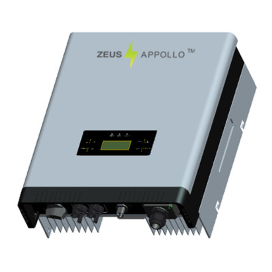
Page 14: Product Appearance
4.2 Product Appearance • Front Object Description Removable front shield LED light (3 pcs) Function keys for displays and choice of language(4 pcs) Monitoring LCD with backlighting • Bottom... -
Page 15: Product Identification
Object Description DC switch (optional) Plug connectors for DC input Terminal for grid connection (AC output) Communication interface (RS485/GPRS/Wi-Fi/USB) 4.3 Product Identification You can identify the inverter by the side nameplate. Information such as the type of inverter, as well as the inverter specifications are contained on the side name plate. The name plate is located on the middle of the right hand side of the inverter housing. -
Page 16: Installation
Installation 5.1 Safety DANGER DANGER to life due to potential fire or electricity shock. DO NOT install the inverter near any flammable or explosive items. This inverter will be directly connected with a HIGH VOLTAGE power generation device; the installation must be performed by qualified personnel only in compliance with national and local standards and regulations. -
Page 17: Safety Clearance
• It is recommended that the inverter is installed vertically, with a max.15 degrees backward tilt. • In order to view the LCD display and undertake maintenance activities, please install the inverter at eye level. • Ensure that the wall selected for installation is strong enough for the mounting screws and can bear the weight of the inverter. -
Page 18: Mounting Procedure
Direction Minimum clearance Above 30 cm Below 40 cm Sides 10 cm 5.4 Mounting Procedure 1. Mark the four (4) positions of the drill holes on the wall corresponding with the wall mounting bracket in the carton. ( Depth 50m m )... - Page 19 2. Where the wall is marked, drill 4 holes and then insert the four expansion tubes into the holes using a rubber hammer. Next insert the 4 screws through the mounting holes in the bracket and then tighten the screws into the expansion tubes. The bracket is now installed. 3.
-
Page 21: Safety Lock
5.5 Safety lock After the inverter is hanging up on the bracket, lock up the device and the bracket together at the Lower Left Corner of the inverter (as per the picture below). Padlock Recommended padlock dimension: A φ . S hackle Diameter 5~7 mm V ertical Clearance... -
Page 22: Electrical Connection
Electrical Connection 6.1 Safety DANGER DANGER to life due to potential fire or electricity shock. When the inverter is powered up, comply with all applicable national regulations and legislation concerning accident prevention. This inverter will be directly connected to a HIGH VOLTAGE power generation device;... - Page 23 leakage current exceeds the permitted range, the RCD will disconnect the inverter from the AC load. 2. Assembly Instructions NOTICE Use 14-12 AWG (2-4mm ) copper wire for all AC wiring connections to the Z10 series inverter. Use only solid wire or stranded wire. 1) Remove length y of N, L conductor 35mm (1.38’’)/PE conductor 40mm (1.57’’) sheath of AC cable terminal, length x about 14mm (0.55’’) of the inner wrapper, then dress the conductor terminals with ferrules or tin soldering.
- Page 24 4) Insert the connector into the clamp ring, it should click twice and then tighten the hex nut with tightening torque of 4Nm. 5) Finally connect the straight plug to the AC terminal on the inverter. Pay attention to the polarity of the terminals to avoid an incorrect connection.
-
Page 25: Dc Side Connection
Inverter, and it can be used to connect or disconnect the DC source from the Inverter. For the Z10I3KD, Z10I4KD and Z10I5KD, there are two MPP Trackers, and the DC characteristics of them are illustrated as the following table. Max. DC Max. - Page 26 It is unadvisable to use non-tinned cables of type H07RN-F, since with oxidized copper wires the contact resistances of the crimp connection may exceed the permitted limits. Disconnected connectors should be protected from dirt and water with sealing caps. Plugged parts are watertight IP67. They cannot be used permanently under water.
-
Page 27: Cable Preparation
(ill. 3) Open-end spanner PV-MS, 1 Set = 2 pieces Order No.: 32.6024 (ill. 4) PV-WZ-AD/GWD socket wrench insert to tighten Order No. 32.6006 (ill. 5) PV-SSE-AD4 socket wrench insert to secure Order No. 32.6026 (ill. 6) Test plug PV-PST Order No. - Page 28 (ill. 11) Open the clamp (K) and hold. Place the contact in the appropriate cross section range. Turn the crimp lugs upwards. Release the clamp (K). The contact is fixed. (ill. 12) Press the pliers gently together until the crimp lugs are properly located within the crimping die.
-
Page 29: Communication And Monitoring Device
(ill. 17) Screw up the cable gland hand-tight with the tools PV-MS or tighten the cable gland with the tools PV-WZ-AD/GWD and PV-SSE-AD4. In both cases: The tightening torque must be appropriate for the solar cables used. Typical values are between 2,5 Nm and 3 Nm. -
Page 30: Display And Operation
Display and Operation 7.1 LCD Panel Object Description LED light(Yellow) – COM LED light(Green) – RUN LED light(Red) – FAULT UP key DOWN key ESC key ENTER key The LCD panel is integrated in the front lid of the inverter for easier user access to check, collate and set data. -
Page 31: Commissioning
NOTICE The Z10 series inverter is not an aligned measuring instrument for current, voltage or power consumption. A slight deviation of a few percent points is inherent to the system; the results from the inverter cannot be used for grid balance calculations. An aligned meter will be required to make calculations for the utility company. -
Page 32: Operation
7.3 Operation 7.3.1 System operation interface System operation interface 1: In this interface, the displayed “Waiting 0” part will switch along with the system operation status. The system will have the following status: 1. Waiting status: Display as Waiting XXX, XXX refers to the countdown time, will display 1~3 numbers. - Page 33 System operation interface 3: This interface displays the input voltage and current of the 2 input PV panel. System operation interface 4: This interface displays the voltage and frequency of grid and the current which inverter outputs to the grid. System operation interface 5: This interface displays the Wi-Fi information of the inverter, including Wi-Fi SN and IP address.
- Page 34 7.3.2 Interface introduction Safety Interface: When choose “Safety” by pressing compound key (ESC+ENTER) in system operation interface 1 for 3 seconds. Safety “Italy” in the screen flickers. After confirm to enter, password dialog box appears. The default password is “654321”. After entering the password, system will get to the safety selection interface.
- Page 35 Austral China GerBDEW Dan mark GreIsla Czech Slovak Holland Sweden Bulgaria France Brazil EngG592 Holl16A SAfrica These safety information will be arranged in 4 lines, i.e. there will be 4 safety information displayed in the same interface. Info Interface: You can choose “Info” by UP and DOWN key in system operation interface 1 While “Info”...
- Page 36 AC grid information: Inverter’s Model information: Inverter’s SN Information:...
- Page 37 Inverter’s master CPU information: Inverter’s slave CPU information: Inverter’s display module version information:...
- Page 38 Error record display interface: You can choose “Error” by UP and DOWN key in system operation interface 1 While “Error” flickers, confirm to enter the Error record mode. Interface number of the Error record mode is unfixed; it ranges from 0 to 9 interfaces. No error record interface: Recent error record interface:...
- Page 39 Earliest error record interface: Set mode: You can choose “Set” by UP and DOWN key in system operation interface 1 While “Set” flickers, confirm to enter the Set mode. The Set mode is operated with 2 levels of menu. There are five items in the sub-menu, Time, Data, Password, Language and Wi-Fi.
- Page 40 Setting Language: In the Set mode, choose Language by Up and Down key (as shown in the picture) While “Language” flickers, confirm to enter the language option list. Choose the target language, the corresponding language flickers. English, Dutch and German are available for displaying. Click ENTER to save data and back to prior menu. Changing Password: In the Set mode, choose “Password”...
- Page 41 While “Password” flickers, confirm to enter the password modified interface. Input 6 figure passwords, check correctness and enter the modified mode Save password after the end of input Back to two-level menu mode after saving the password Setting Time: In the Set mode, choose “Time” by UP and DOWN key as shown in the picture.
- Page 42 While “Time” flickers, confirm to enter the inverter time setting mode. There are hour, minute and second displayed in the time setting mode. Use ENTER key to choose the one you want to modify and UP/DOWN key to change the value. Setting Date: In the Set mode, choose “Date”...
-
Page 43: State Information
7.4 State Information State Display State information Waiting Initialization & waiting Wait Reconnects Reconnect Checkings Checking Normal Normal Normal state Current Fault GFCI failure oversized leakage current Master Grid Freq Fault Grid frequency failure Master Grid Freq Fault Grid voltage failure PV Voltage Fault Input voltage too high Over Temp Fault... -
Page 44: Troubleshooting
1. Check the open PV voltage; see if it is greater than or too close PV Voltage Fault to 590VDC (for Z10I3KD or Z10I4KD or Z10I5KD). 2. If PV voltage is less than 590VDC, and the problem still occurs, please call local service. - Page 45 Error code list : : : : ERROR CODE Description GFCI Device Fault Hole Sense Device Fault Reference Device Fault DCI ENS Fault GFCI ENS Fault Less Bus Low Voltage Fault Over Bus High Voltage Fault Master Device Fault Master Delta Grid Z Fault No Utility Current Fault Bus Voltage Fault...
-
Page 46: Abbreviation
Abbreviation Liquid Crystal Display Light Emitting Diode MPPT Maximum Power Point Tracking Photovoltaic Voltage at the DC side Voltage at the AC side Vmpp Voltage at the Maximum Power Point Impp Amperage at Maximum Power Point Alternating Current ( Form of electricity supplied by Utility Company ) Direct Current ( Form of electricity generated by PV modules ) -
Page 47: Contact
10. Contact Beijing Hua Xin Liu He Investment (Australia) Pty Ltd. Website: www.zeusappollo.com Perth Office 1/87 President Street Welshpool, WA 6106 Phone: (08) 6555 6518 Fax: (08) 9470 4103 Email: sales@zeusappollosolar.com.au Brisbane Office 32 Crockford Street Banyo, QLD 4014 Phone: (07) 3123 6148 Fax: (07) 3266 4758 Email: bris@zeusappollosolar.com.au...
Need help?
Do you have a question about the Z10I3KD and is the answer not in the manual?
Questions and answers