Table of Contents
Advertisement
Advertisement
Table of Contents

Related Manuals for Bosch PVA-4R24


Summary of Contents for Bosch PVA-4R24
- Page 1 PAVIRO Router PVA-4R24 Operation manual...
-
Page 3: Table Of Contents
PAVIRO Router Table of contents | en Table of contents Safety Short information System overview Front panel Rear panel Parts included Installation Connection Audio input Audio output Supply voltage CAN BUS Control input Control output Configuration Setting the CAN address Displaying the CAN baud rate Configuring the CAN baud rate Operation... -
Page 4: Safety
en | Safety PAVIRO Router Safety Danger! High risk: This symbol indicates an imminently hazardous situation such as "Dangerous Voltage" inside the product. If not avoided, this will result in an electrical shock, serious bodily injury, or death. Warning! Medium risk: Indicates a potentially hazardous situation. If not avoided, this could result in minor or moderate bodily injury. - Page 5 PAVIRO Router Safety | en 13. Use only with the cart, stand, tripod, bracket or table specified by the manufacturer, or sold with the apparatus. – When a cart is used, use caution when moving the cart/ apparatus combination to avoid injury from tip-over. Quick stops, excessive force, and uneven surfaces may cause the appliance and cart combination to overturn.
- Page 6 en | Safety PAVIRO Router Danger! Object and Liquid entry – Never push objects of any kind into this apparatus through openings as they may touch dangerous voltage points or short-out parts that could result in a fire or electric shock. Never spill liquid of any kind on the apparatus. 25.
- Page 7 PAVIRO Router Safety | en Warning! To avoid electric shock, do not connect safety extra-low voltage (SELV) circuits to telephone- network voltage (TNV) circuits. LAN ports contain SELV circuits, and WAN ports contain TNV circuits. Some LAN and WAN ports both use RJ‑45 connectors. Use caution when connecting cables.
-
Page 8: Short Information
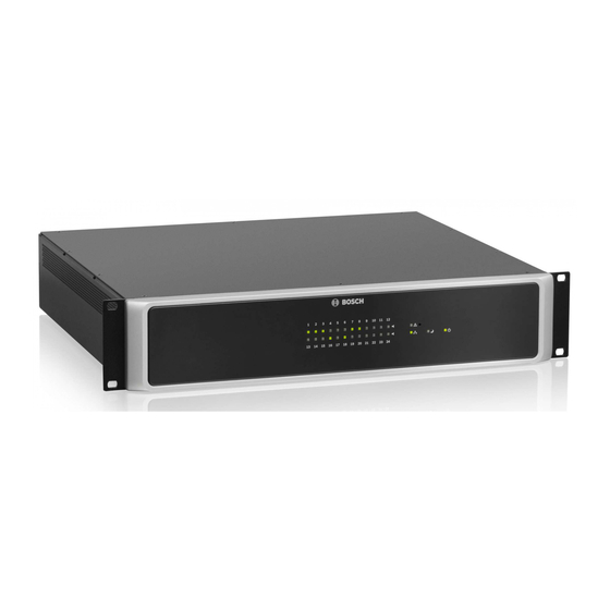
PAVIRO Router Short information The PVA-4R24 24 Zone Router is a zone extension for the PAVIRO system. The PVA-4R24 adds 24 zones, 20 GPIs, 24 GPOs and 2 control relays to the system and is controlled and supervised via the CAN bus by the PVA-4CR12 (Controller). Up to 20 external routers can be connected to one controller. -
Page 9: System Overview
PAVIRO Router System overview | en System overview Front panel Number Symbol Element Description Zone status Indicates the status of the zone: indicator light – Green = Zone is in use for non-emergency purpose – Yellow = Zone fault detected (Note: The indication of this status has the highest priority) –... - Page 10 en | System overview PAVIRO Router Number Symbol Element Description Recessed button The button is protected to prevent it from being pressed accidentally. Use a pointed object (such as a ballpoint pen) to press the button. This button has the following functions if the CAN address of the device is not set to 00: –...
-
Page 11: Rear Panel
PAVIRO Router System overview | en Rear panel Number Element Description 1 Grounding screw Ground connection 2 CONTROL IN ports Control port with isolated or supervised inputs. Please refer to section Control input, page 20. 3 CONTROL OUT ports Control port with open collector outputs. Please refer to section Control output, page 21. -
Page 12: Parts Included
| Parts included PAVIRO Router Parts included Quantity Component PVA-4R24 Euroblock connector 2-pole (Phoenix, PC 5/2-STF-7,62, 1975697, F.01U. 108.398) for 24 V DC Euroblock connector 6-pole (Phoenix, MC 1,5/6-ST-3,81, 1827745, F.01U. 104.179) for audio inputs Euroblock connector 10-pole (Phoenix, MC 1,5/10-STF-3,81, 1827787, F.01U. -
Page 13: Installation
PAVIRO Router Installation | en Installation This device has been designed to be installed horizontally in a conventional 19” rack cabinet. Front attachment of the device Refer to the following illustration to attach the front of the device, using four screws and washers. - Page 14 en | Installation PAVIRO Router – Strong vibrations If these requirements cannot be guaranteed, the device must be regularly serviced to prevent any outages that could occur as a result of negative ambient conditions. If a solid object or fluid enters the housing, immediately disconnect the device from the voltage supply, and have it serviced by an authorized technician before it is recommissioned.
-
Page 15: Connection
Following illustration gives an overview of possible routings between the AMP IN audio inputs and the SPEAKER OUT audio outputs using the internal relays of the device. The PVA-4R24 includes four 2-in-6 routing blocks A, B, C or D. Each routing block provides 2 regular inputs, 1 spare amplifier input and 6 outputs. -
Page 16: Audio Output
en | Connection PAVIRO Router Audio output 12-May-2015 | 03 | F01U306901 Operation manual... -
Page 17: Supply Voltage
PAVIRO Router Connection | en The audio outputs on the device allow to connect 100 V (or 70 V) loudspeaker zones. The delivery includes 12-pin connectors. Conductor cross-sections of 0.14 mm² (AWG26) to 1.5 mm² (AWG16) can be used. Recommended connecting cable: flexible CU strand, LiY, 0.75 mm². For ease of installation, the connector can be removed. -
Page 18: Can Bus
en | Connection PAVIRO Router CAN BUS This section contains information about the connection of the device to the CAN BUS and the correct setting of the CAN address. Connection The device has two RJ-45 jacks for the CAN BUS. The jacks are connected in parallel, and act as an input and for daisy chaining the network. - Page 19 PAVIRO Router Connection | en Figure 6.2: Assignment of the CAN connector Designation Cable color T568A T568B CAN_GND Green Orange CAN_H (+) Blue CAN_L (-) Blue stripes Table 6.2: Assignment of the CAN BUS interface Cable specification In accordance with the ISO 11898-2 standard, shielded twisted-pair cables with an impedance of 120 ohms must be used as the data transfer cable for the CAN bus.
-
Page 20: Control Input
en | Connection PAVIRO Router Bus length (in m) Number of devices on the CAN Bus 0.25 mm² or AWG24 0.34 mm² or AWG22 0.34 mm² or AWG22 0.34 mm² or AWG22 0.5 mm² or AWG20 0.5 mm² or AWG20 0.75 mm²... -
Page 21: Control Output
PAVIRO Router Connection | en Figure 6.3: Using supervised or isolated inputs of the CONTROL IN port Supervised control inputs The supervised control inputs can be used as – normal logical (high/low) input (with low <= 5 V or high >= 10 V) or –... - Page 22 en | Connection PAVIRO Router Control outputs The freely programmable control outputs are designed as open collector outputs that have a high resistance (open) when not active (OFF/inactive). When active (ON/active), the outputs are closed to ground. Caution! The maximum permissible current per output is 40 mA. The maximum permissible voltage is 32 V.
- Page 23 PAVIRO Router Connection | en 4CR12 4R24 Figure 6.5: Internal configuration of the REL contact (VDE 0833-4) Operation manual 12-May-2015 | 03 | F01U306901...
-
Page 24: Configuration
en | Configuration PAVIRO Router Configuration Setting the CAN address The CAN address of the device is set using the two address selector switches HIGH and LOW. Addresses 1 to 250 (01 hex to FA hex) can be used in a CAN network. The address is set using the hexadecimal numbering system. -
Page 25: Displaying The Can Baud Rate
PAVIRO Router Configuration | en HIGH Address 0 to A 240 to 250 B to F Reserved Table 7.1: CAN addresses Displaying the CAN baud rate To display the CAN baud rate, press the Recessed button and keep the button pressed down for at least one second. -
Page 26: Operation
en | Operation PAVIRO Router Operation Line supervision For loudspeaker line supervision three different options are available. They differ in performance, cost, and suitability for various applications and situations. In general the device can detect open circuit and short circuit. In case of an open circuit only a fault message will be generated. -
Page 27: Plena Eol
PAVIRO Router Operation | en Method of operation An EOL slave module PVA-1WEOL is installed at the end of the speaker line. The speaker line is used for both the power supply of the module (via the non-audible pilot tone) and for bi- directional communication between the EOL master in the output stage and the EOL slave module (using very low-frequency signals). -
Page 28: Pilot Tone
en | Operation PAVIRO Router at the end of the loudspeaker line, this applies to the integrity of the whole line. Presence of the pilot tone signal does not depend on the number of loudspeakers on the line, the load on the line, or the line capacitance. -
Page 29: Maintenance
PAVIRO Router Maintenance | en Maintenance Firmware update IRIS-Net can be used to update the firmware on the device. Depending on the CAN data rate used, the update will take one or more minutes to complete. Since development work is always being performed in relation to all system software, it may be necessary to update the firmware on the controller. -
Page 30: Technical Data
| Technical data PAVIRO Router Technical data PVA-4R24 24 Zone Router PAVIRO Router including routing and supervision AMP IN: 4 ✕ 6-pin port Audio inputs (100 V) – Max. voltage 120 V – Max. current 7.2 A – Max. power 500 W SPEAKER OUT: 4 ✕... -
Page 31: Standards
PAVIRO Router Technical data | en 10.1 Standards The device meets the following standards (as of February 2015): – EN 50130-4 – EN 50581 – IEC 60065 – EN 60945 – EN 60950 – EN 61000-6-3 10.2 Dimensions Operation manual 12-May-2015 | 03 | F01U306901... - Page 34 Bosch Security Systems B.V. Torenallee 49 5617 BA Eindhoven The Netherlands www.boschsecurity.com © Bosch Security Systems B.V., 2015...
Need help?
Do you have a question about the PVA-4R24 and is the answer not in the manual?
Questions and answers