
Subscribe to Our Youtube Channel
Related Manuals for York YOHC 12


Summary of Contents for York YOHC 12
-
Page 1: Service Manual
Convertible Console YOHC 12 to 60 SERVICE MANUAL YOHC 12 · YOHC 18 · YOHC 24 YOHC 36 · YOHC 48 · YOHC 60 SM-YOHC-12-60GB 03-07... - Page 2 Contents Part 1 General information…………………………………………………. Part 2 Indoor units…………………………………………………………… Part 3 Outdoor units……………………………………………………….. Part 4 Installation…………………...……………………………………… Part 5 Control………………………………………………………………..
-
Page 3: General Information
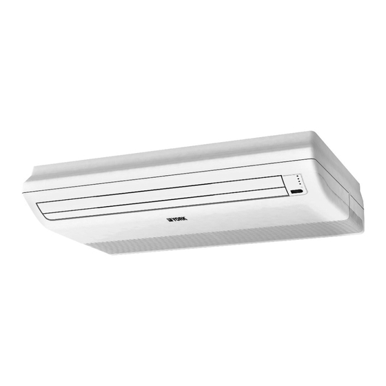
Part 1 General Information 1. Model names of Indoor/Outdoor Units…………………………………… 2. External Appearance………………………………………………………... 3. Nomenclature………………………………………………………………… 4. Features……………………………………………………………………….. - Page 4 Model Names of Indoor/ Outdoor Units Model Names of Indoor Units: YOKC-12 YOKC-18 YOKC-24 YOKC-30 YOKC-36 YOKC- 48 YOKC-60 Model Names of Outdoor Units: YOJC-12 YOJC-18 YOJC-24 YOJC-30 YOJC-36 YOJC-48 YOJC-60 1. External Appearance 1.1 Indoor units 1.2 Outdoor units...
- Page 5 A = First H = High wall R = New remote M = Master range P = Portable Y = YORK Voltages: R = Everest front A = (Out) 220-240/1/50 - (In) 220-240/1/50 C = (Out) 380/3/50 - (In) 220-240/1/50...
- Page 6 3. Features 4.1. New design, more modern and elegant appearance; 4.2. Convenient installation; 4.3. Two direction auto swing (vertical & horizontal) and wide angle air flow; 4.4. Three level fan speed, more humanism design, meets different air-supply requirement; 4.5. Water proof by utilizing the absorbing plastic film on water collector; 4.6.
-
Page 7: Indoor Units
Part 2 Indoor units Ceiling & Floor Type…………………………………………………………... -
Page 8: Table Of Contents
Ceiling & Floor Type 1. Features…………………………………………………………………………………………….. 2. Specification……………………………………………………………………………………….. 3. Dimensions……………………………………………………………………………………….. 4. Service space…………………………………………………………………………………….. 5. Piping diagrams………………………………………………………………………………….. 6. Wiring diagrams………………………………………………………………………………….. 7. Capacity Tables…………………………………………………………………………………... 8. Air Velocity and Temperature Distributions…………………………………………………. 9. Electric Characteristics…………………………………………………………………………. 10. Sound Levels……………………………………………………………………………………... 11. Exploded view……………………………………………………………………………………. - Page 9 1. Features 1.1. New design, more modern and elegant appearance. 1.2. Convenient installation --The ceiling type can be easily installed into a corner of the ceiling even if the ceiling is very narrow --It is especially useful when installation of an air conditioner in the center of the ceiling is impossible due to a structure such as one lighting 1.3.
- Page 10 2. Specification Model YOHC -12 YOHC -18 YOHC -24 Power supply Ph-V-Hz 1,220-240V,50Hz 1,220-240V,50Hz 1,220-240V,50Hz Capacity 12000 18000 24000 Btu/h Capacity Cooling Input 1200 1900 2700 Rated current 12.0 Btu/W.h 10.0 Capacity Btu/h 13500 20000 26000 Capacity Heating Input 1130 1850 2800 Rated current...
- Page 11 Dimension (W*H*D)(body) 995×660×198 995×660×198 995×660×198 Indoor unit 1089×744×296 1089×744×296 1089×744×296 Packing (W*H*D)(body) Net/Gross weight(body) 27/33 27/33 27/33 YDK24-6F YDK53-6K YDK53-6H Model Outdoor fan Input motor Capacitor 2.5uF/450V 3uF/450V 3µF/450V Speed r/min Number of rows Tube pitch(a)x row pitch(b) 21x13.37 25.4×22 25.4×22 Fin spacing Fin type...
- Page 12 Model YOHC -30 YOHC -30 YOHC -36 Power supply Ph-V-Hz 3,380V,50Hz 1,220-240V,50Hz 1,220-240V,50Hz 30000 30000 36,000 Capacity Btu/h 10.5 Capacity Cooling Input 3750 3750 3750 Rated current 16.3 16.3 Btu/W.h Capacity Btu/h 32000 32000 39000 Capacity 11.4 Heating Input 3500 3500 3500 Rated current...
- Page 13 Dimension (W*H*D)(body) 1285×660×198 1285×660×198 1285×660×198 Indoor unit 1365×744×278 1365×744×278 1365×744×278 Packing (W*H*D)(body) 34/42 34/42 34/42 Net/Gross weight(body) Model YDK250-6D YDK250-6D YDK250-6D Outdoor fan Input motor 10µF/450V 10 uF/450V 10 uF/450V Capacitor Speed r/min Number of rows Tube pitch(a)x row pitch(b) 25.4×22 25.4×22 25.4×22...
- Page 14 Model YOHC -36 YOHC -48 YOHC -60 Power supply Ph-V-Hz 3,380V,50Hz 3,380V,50Hz 3,380V,50Hz Capacity Btu/h 36000 48000 60,000 Capacity 10.5 Cooling Input 3750 4700 6000 Rated current Btu/W.h 10.2 10.0 39000 52000 68,000 Capacity Btu/h Capacity 11.4 15.2 Heating Input 3700 4900 6000...
- Page 15 1285×660×198 1670×680×240 1670×680×240 Dimension (W*H*D)(body) Indoor unit 1365×744×278 1764×760×329 1764×760×329 Packing (W*H*D)(body) Net/Gross weight(body) 34/42 52/62 52/62 Model YDK250-6D YDK65-6; YDK65-6F YDK65-6F; YDK65-6F Outdoor fan Input 138+156 138+156 motor Capacitor 10 uF/450V 3.5×2 uF/450V 3.5×2 uF/450V Speed r/min Number of rows 25.4×22 25.4×22 25.4×22...
- Page 16 3. Dimensions 3.1. YOKC-12 YOKC-18 YOKC-24 Strengthener 4-12 18 Overhanging hole ¡ Á Drain point Connecting point of refrigerant pipe (Liquid side) Connecting point of refrigerant pipe (gas side) 3.2. YOKC-30 YOKC-36 1285 Strengthener 4-12 18 Overhanging hole ¡ Á Drain point Connecting point of refrigerant pipe...
- Page 17 4. Service space >600mm...
-
Page 18: Piping Diagrams
5. Piping Diagrams Remark: 1. For YOJC-12 and YOJC-18, accumulator is not included. 2. For YOJC-30, YOJC-36 and YOJC-48, check valve and auxiliary capillary is not included. -
Page 19: Wiring Diagrams
6. Wiring Diagrams 6.1 Cooling & Heating 6.1.1 YOKC-12 D I S P LA Y B O A R D X P 1 X S 1 I N D O O R W I R I N G D I A G R A M C O D E P A R T N A M E C N 10... - Page 20 6.1.3. YOKC -24 6.1.4. YOKC -30...
- Page 21 6.1.5. YOKC -36 6.1.6. YOKC -48 YOKC -60...
-
Page 22: Capacity Tables
7. Capacity Tables Model: YOHC-12 Cooling OUTDOOR TEMPERATURE DRY Indoor 21ºC 25ºC 30ºC 35ºC 40ºC 45ºC 50ºC Conditions Total capacity kW 3.38 3.23 3.12 2.94 2.82 2.73 2.65 21ºC D Sensitive capacity kW 2.70 2.59 2.49 2.35 2.26 2.19 2.12 15ºC W Input kW. - Page 23 Model: YOHC -18 Cooling OUTDOOR TEMPERATURE DRY Indoor 21ºC 25ºC 30ºC 35ºC 40ºC 45ºC 50ºC Conditions Total capacity kW 5.22 4.99 4.81 4.54 4.35 4.22 4.08 21ºC D Sensitive capacity kW 4.17 3.99 3.85 3.63 3.48 3.37 3.27 15ºC W Input kW.
- Page 24 Model: YOHC -24 Cooling OUTDOOR TEMPERATURE DRY Indoor 21ºC 25ºC 30ºC 35ºC 40ºC 45ºC 50ºC Conditions Total capacity kW 6.86 6.56 6.32 5.96 5.73 5.55 5.37 21ºC D Sensitive capacity kW 5.49 5.25 5.06 4.77 4.58 4.44 4.29 15ºC W Input kW.
- Page 25 Model: YOHC -30 Cooling OUTDOOR TEMPERATURE DRY Indoor 21ºC 25ºC 30ºC 35ºC 40ºC 45ºC 50ºC Conditions Total capacity kW 8.89 8.50 8.19 7.73 7.42 7.19 6.96 21ºC D Sensitive capacity kW 7.11 6.80 6.55 6.18 5.94 5.75 5.56 15ºC W Input kW.
- Page 26 Model: YOHC -36 Cooling OUTDOOR TEMPERATURE DRY Indoor 21ºC 25ºC 30ºC 35ºC 40ºC 45ºC 50ºC Conditions Total capacity kW 10.14 9.70 9.35 8.82 8.47 8.20 7.94 21ºC D Sensitive capacity kW 8.11 7.76 7.48 7.06 6.77 6.56 6.35 15ºC W Input kW.
- Page 27 Model: YOHC -48 Cooling OUTDOOR TEMPERATURE DRY Indoor 21ºC 25ºC 30ºC 35ºC 40ºC 45ºC 50ºC Conditions Total capacity kW 13.52 12.94 12.47 11.76 11.29 10.94 10.58 21ºC D Sensitive capacity kW 10.82 10.35 9.97 9.41 9.03 8.75 8.47 15ºC W Input kW.
- Page 28 Model: YOHC -60 Cooling OUTDOOR TEMPERATURE DRY Indoor 21ºC 25ºC 30ºC 35ºC 40ºC 45ºC 50ºC Conditions Total capacity kW 16.42 15.71 15.14 14.28 13.71 13.28 12.85 21ºC D Sensitive capacity kW 13.14 12.57 12.11 11.42 10.97 10.62 10.28 15ºC W Input kW.
- Page 29 8. Air Velocity and Temperature Distributions Discharge angle 60° (CEILING) Airflow velocity Temperature...
- Page 30 Discharge angle 60°(FLOOR) Airflow velocity Temperature...
-
Page 31: Electric Characteristics
9. Electric Characteristics Power supply Indoor fan motor Model Voltage Power output YOKC-12 220~240 0.13 YOKC-18 220~240 0.355 YOKC -24 220~240 0.355 YOKC-30 220~240 0.475 YOKC-36 0.475 YOKC-48 0.34 YOKC-60 0.34 Symbols: FLA: Full Load Amps. -
Page 32: Sound Levels
10. Sound Levels Ceiling Floor High airflow ¸ ß · ç µ Í · ç Low airflow 12000btu/h 18000btu/h Audibility limits of Audibility limits of continuous white continuous white sound sound Octave band center frequency £ ¨ H z £ © Octave band center frequency £... - Page 33 24000btu/h 30000btu/h 36000btu/h A udibility lim its of Audibility limits of continuous w hite continuous white sound sound O ctave band center frequency £ ¨ H z £ © Octave band center frequency £ ¨ H z £ © Ceiling Floor 48000btu/h 60000btu/h Audibility limits of...
- Page 34 11. Exploded view 11.1 YOKC-12 YOKC-18 YOKC -24 Part Name Quantity Part Name Quantity Air inlet grille Installation clamp filter Right holder,eva Electric control assy Base pan Electric part box Evaporator Wire joint 23.1 Electric expansive valve Wire joint “ROHS” 23.2 Electric Expansion loop Pipe Temperature Sensor Ass'y II left holder, eva...
- Page 35 11.2 YOKC-30 YOKC-36 Part Name Quantity Part Name Quantity Air inlet grille Right holder,eva filter Base pan E-Parts box ass'y Evaporator Electric part box left holder, eva Wire joint left fixed board, eva Wire joint left frame holder, eva Pipe temp. sensor ass'y left clapboard Room temp.
- Page 36 11.3 YOKC-48 YOKC-60 Part Name Quantity Part Name Quantity Air inlet grille left sealing board filter left clapboard left fixing clamp for motor E-Parts box ass'y right fixing clamp for motor 25.1 Wire joint Strenghten board for motor 25.2 Wire joint E-part box underlay 25.3 Pipe temp.
-
Page 37: Outdoor Units
Part 3 Outdoor Units Outdoor Units……………………………………………………………….. - Page 38 Outdoor Units 1. Dimensions…………………………………………………………………………………….. 2. Service Space………………………………………………………………………………….. 3. Wiring Diagrams………………………………………………………………………………. 4. Field Wiring…………………………………………………………………………………….. 4. Electric Characteristics……………………………………………………………………… 6. Operation Limits………………………………………………………………………………. 7. Sound Levels………………………………………………………………………………….. 8. Exploded view…………………………………………………………………………………. 9. Troubleshooting……………………………………………………………………………….
- Page 39 1. Dimensions 1.1 YOJC-12 1.2. YOJC-18...
- Page 40 1.3. YOJC-24 1.4. YOJC-30 YOJC-36...
- Page 41 1.5. YOJC-48 YOJC-60...
-
Page 42: Service Space
2. Service Space Capacity≤60000Btu Obstacle (Wall or obstacle) Air inlet >30cm Fix with bolt Air inlet Maintain channel >60cm Air outlet Deep foundation Necessary width 600mm M10 bolt 4pieces per unit... - Page 43 3. Wiring diagrams 3.1 Cooling & Heating 3.1.1. YOJC-12 3.1.2. YOJC-18...
- Page 44 3.1.3. YOJC-24 3.1.4. YOJC-30 R E S S TA R T I N G C A P A C I T O R S TA R T I N G R E LA Y W AR N I N G : I F TH E I N D O O R U N I T I S T1&T2&D L R E S D I S C H A R G E R E S I S T A N C E...
- Page 45 3.1.5. YOJC-36 3.1.6. YOJC-48 YOJC-60 H - P R O C N 201 B A C K ( H I ) R E D ( LO W ) B LAC K( L1) KM 1 XT 5 C O M P R E S S O R FA N 3 FA N 4 O U TD O O R FA N BLU E...
- Page 46 4. Field Wiring...
- Page 47 5. Electric Characteristics Power supply Compressor Outdoor fan motor Model Voltage Power output YOJC-12 220~240 0.27 YOJC -18 220~240 36.8 8.75 0.61 YOJC -24 220~240 11.4 0.66 YOJC -30 220~240 17.65 1.38 YOJC -36 6.58 1.38 YOJC -48 8.22 YOJC -60 9.77 Symbols: MSC: Max.
-
Page 48: Operation Limits
6. Operation Limits Ensure the operating temperature is in allowable range. Heating Cooling With low ambient temp. cooling module Indoor temp. (ºC) Indoor temp. (ºC) - Page 49 7. Sound levels Microphone 12000btu/h 18000btu/h...
- Page 50 24000btu/h 3000btu/h & 36000btu/h 48000btu/h & 60000btu/h...
- Page 51 8. Exploded view 8.1 Cooling & Heating 8.1.1 YOJC-12 Part Name Quantity Part Name Quantity Clamp for front net Capacitor clamp Front net Wire joint,5p Front clapboard Wire joint, 2p Propeller fan Left supporter Fan motor Separating board Holder for fan motor Condenser Chassis Water collector...
- Page 52 8.1.2 YOJC-18 Part Name Quantity Part Name Quantity Clamp for front net Wire joint Front net Separating board Front clapboard Installation board for E-parts Propeller fan Washer for wire joint Fan motor Clamp for wiring Holder for fan motor Compressor capacitor Foam over holder for motor Capacitor clamp Cover...
- Page 53 8.1.3 YOJC-24 Part Name Quantity Part Name Quantity Front net AC contactor Cabinet,Front Capacitor,Fan Motor Fan,Propeller Wire Clamp Fan Motor Terminal Block,5p Mount,Fan Motor Terminal Block,2p Topcap Ass'y Compressor Condenser Ass'y Fixture,Segregator Inlet Pipe for Condenser 4-way Valve Outlet Pipe for Condenser 4-way Valve Solenoid Rear Net Liquid pipe valve...
- Page 54 8.1.4 YOJC-30 Part Name Quantity Part Name Quantity Clamp for front net Fan motor capacitor Front net Installation board for E-parts Front clapboard AC contactor Propeller fan Main control box Fan motor Wire joint for multiplexer Holder for fan motor Wire joint for multiplexer Chassis Washer for wire joint...
- Page 55 8.1.5 YOJC-36 Part Name Quantity Part Name Quantity Clamp for front net Fan motor capacitor Front net Installation board for E-parts Front clapboard AC contactor Propeller fan Main control board,Outdoor unit Fan motor Wire joint for multiplexer Holder for fan motor Wire joint for multiplexer Chassis Washer for wire joint...
- Page 56 8.1.6 YOJC-48 Part Name Quantity Part Name Quantity Front net Capacitor,Fan Motor Cabinet,Front Terminal Block,2p Fan,Propeller AC contactor Fan Motor Low Pressure Valve Room temp. sensor,outdoor PCB board,outdoor unit Mount,Fan Motor Terminal Block,3p Topcap Ass'y Wire joint for power Condensator I Compressor Condensator II Refrigerator Container...
- Page 57 8.1.7 YOJC-60 Part Name Quantity Part Name Quantity Guard fan Capacitor,Fan Motor Cabinet,Front Terminal Block,2p Fan,Propeller AC contactor Fan Motor Low Pressure Valve . Room temp. sensor,outdoor PCB board,outdoor unit Mount,Fan Motor Terminal Block,4p Topcap Ass'y Wire joint for power Condensator I Compressor Condensator II...
-
Page 58: Troubleshooting
9. Troubleshooting 9.1 Indoor unit’s LED indication of trouble Protection or Malfunction Operation Timer lamp Defrosting Auto lamp lamp recover Indoor temp. sensor abnormal × × Indoor heat exchanger sensor abnormal × × Outdoor heat exchanger sensor abnormal × × Outdoor abnormal EEPROM abnormal ×... - Page 59 9.2.1 Phase sequence error: Phase sequence error Change the order of two of the wires to power supply. Switch on the unit again. If the problem can not be solved, the outdoor PCB is defective 9.2.2 Overload of current Overload of current Check the current, normally The max.
- Page 60 9.2.3 Lack of phase Lack of phase Check the power supply, is it 3 phase, Check the connection between power supply and terminal, Outdoor PCB is defective...
- Page 61 9.2.4 Protection of pressure or temp. Protection of pressure or temp. Is it k1 or K2 open ? Is temp. protective switch K1 Is pressure protective switch Possible reason Possible reason 1. The wires is loose to K1 1. The wires is loose to K 2.
- Page 62 9.2.5 Open-circuit and short-circuit trouble of T3 Is connection to connector of temp. sensor good? Repair connector Check the resistance of the temp. sensor according to Annex 1 Is it the resistance is normal? Indoor PCB is defective. Replace the sensor 9.2.6 Open-circuit and short-circuit trouble of T4 Is connection to connector of temp.
- Page 63 9.2.7 High temperature protection of condenser High temperature protection of condenser Check the resistance of the temp. sensor according to Annex 1, is it normal? Possible reason Replace the sensor 1. Air or other gas in the refrigerant. 2. Heat exchanger is dirty 3.
- Page 64 9.3 Troubles and Solutions If any the following abnormal conditions occur, turn off the power supply immediately. Please contact our dealer. TROUBLES Indicator lamps flash rapidly, after your disconnecting and connecting the unit, the situation is the same. Fuse or circuit breaker work frequently. Foreign matter or water has fallen into the unit.
- Page 65 9.4 Troubles and solutions concerning the remote controller Please make the following check before asking for repair or maintenance. Trouble Cause Solutions Check if the mode display on the The lndoor Unit will select fan speed LCD is AUTO automatically when AUTO mode is CAN NOT CHANGE selected.
- Page 66 Part 4 Installation Installation……………………………………………………………………...
-
Page 67: Refrigerant Pipe Installation
1. Refrigerant pipe installation 1.1. Measure the necessary length of the connecting pipe, and make it by the following way. Connect the indoor unit at first, then the outdoor unit. Bend the tubing in proper way. Do not harm them. CAUTIONS: Daub the surfaces of the flare pipe and the joint nuts with frozen oil, and wrench it for 3~4 rounds With hands before fasten the flare nuts. -
Page 68: Vacuum Dry And Leakage Checking
2. Vacuum dry and leakage checking 2.1. Vacuum Dry: use vacuum pump to change the moisture (liquid) into steam (gas) in the pipe and discharge it out of the pipe to make the pipe dry. Under one atmospheric pressure, the boiling point of water(steam temperature) is 100 . - Page 69 Sketch map of common vacuum dry procedure. Special vacuum dry procedure This vacuum dry method is used in the following conditions: There’s moisture when flushing the refrigerant pipe. Rainwater may enter into th e pipe. Vacuum dry for the first time ······ 2h pumping .
-
Page 70: Additional Charge
3. Additional charge 3.1. When the length of the one-way pipe is less than 5m, additional refrigerant charge after vacuuming is unnecessary. 3.2. When the length of one-way pipe is over 5m, the additional charge quantity is as follows (unit in gram): Calculation method Refrigerant Liquid diameter mm... - Page 71 4.2 Drainpipe Trap 4.2.1. If the pressure at the connection of the drainpipe is negative, it needs to design drainpipe trap. 4.2.2. Every indoor unit needs one drainpipe trap. 4.2.3. A plug should be designed to do cleaning. P l ug 4.3 Upwards drainage(drain pump) 4.3.1.
- Page 72 4.4 Convergent drainage 4.4.1. The number of indoor units should be as small as possible to prevent the traverse main pipe overlong. 4.4.2. Indoor unit with drain pump and indoor unit without drain pump should be in different drainage system. 4.4.3.
-
Page 73: Insulation Work
5. Insulation work 5.1 Insulation material and thickness 5.1.1. Insulation material Insulation material should adopt the material which is able to endure the pipe’s temperature: no less than 70 in the high-pressure side, no less than 120 in the low-pressure side(For the cooling type machine, no requirements at the low-pressure side.) Example: Heat pump type----Heat-resistant Polyethylene foam (withstand above 120 ) Cooling only type---- Polyethylene foam (withstand above 100 ) - Page 74 For construction convenience, before laying pipes, use insulation material to insulate the pipes to be deal with, at the same time, at two ends of the pipe, remain some length not to be insulated, in order to be welded and check the leakage after laying the pipes.
- Page 75 www.johnsoncontrols.com SM-YOHC-12-60GB 03-07...
Need help?
Do you have a question about the YOHC 12 and is the answer not in the manual?
Questions and answers