
Related Manuals for York YCM Series


Summary of Contents for York YCM Series
- Page 1 YCM Air Handling Unit Installation,Operation and Maintenance Manual FORM NO.: 6A6J-A01C-NA-EN...
-
Page 2: Table Of Contents
Calalogue Calalogue I. Overview................................... 3 1-1 Brief Introduction ..............................3 1-2 Model of Air Handling Unit ..........................3 1-3 Outlines & Dimensions ............................5 II. Installation & Transportation ............................ 2 2-1 Matters Needing Attention ..........................2-2 Transportation ..............................2-3 Preparations Before Installation........................2-4 Space of Installation ............................ -
Page 3: Overview
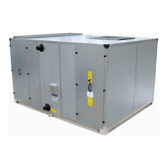
I. Overview 1-1 Brief Introduction York YCM series air handling unit is designed for factories, warehouses, office building and shopping malls. It provides them a comfortable air conditioning environment. The coil of this air handling unit can use heating water to heat air in winter, chilled water to cool air in summer. - Page 4 Overview Note: Along the airflow direction, it is the right hand unit if coil connection pipes are on the right side of unit, vice versa. 1-2-2 The types of supply air Vertical unit...
-
Page 5: Outlines & Dimensions
Overview Horizontal unit 1-3 Outlines & Dimensions 1-3-1 Supply Air Method-Vertical Unit Vertical Standard Unit (V1)-Top Outlet Note: The above apply to left hand unit. For right hand unit, the coil connection pipes are on the right of unit and the outlet should be orientated from the left side of unit. - Page 6 Overview 1-3-2 Supply Air Method-Horizontal Unit Horizontal Standard Unit (H1)-Top Outlet Horizontal Standard Unit (H1)-Front Outlet Note: The above applies to left hand unit. For right hand unit, the coil connection pipes are on the right of unit and the outlet should be orientated from the left side of unit.
- Page 7 Overview Horizontal Standard Unit (H3)-Front Outlet Note: The above applies to left hand unit. For right hand unit, the coil connection pipes are on the right of unit and the outlet should be orientated from the left side of unit. Horizontal Standard Unit (H4)-Top Outlet Horizontal Standard Unit (H4)-Front Outlet Note: The above applies to left hand unit.
- Page 8 Overview outlet should be orientated from the left side of unit. Horizontal Standard Unit (H5)-Top Outlet Horizontal Standard Unit (H5)-Front Outlet Note: The above applies to left hand unit. For right hand unit, the coil connection pipes are on the right of unit and the outlet should be orientated from the left side of unit.
- Page 9 Overview 1-3-3 Outlines & Dimensions Vertical Unit (V1)
- Page 10 Overview...
- Page 11 Overview Horizontal Unit (H1)
- Page 12 Overview...
- Page 13 Overview Horizontal Unit (H2)
- Page 14 Overview...
- Page 15 Overview Horizontal Unit (H3)
- Page 16 Overview...
- Page 17 Overview Horizontal Unit (H4)
- Page 18 Overview...
- Page 19 Overview Horizontal Unit (H5)
- Page 20 Overview...
- Page 21 Overview 1-3-4 Connection pipe Vertical Unit Coil Connection Pipe mm(inch) Model 4 Rows 6 Rows 4 Rows 6 Rows Return Air Return Air Fresh Air Fresh Air YCM02V φ48(1-1/2") φ48(1-1/2") φ48(1-1/2") φ48(1-1/2") YCM03V φ48(1-1/2") φ48(1-1/2") φ48(1-1/2") φ60(2") YCM04V φ48(1-1/2") φ48(1-1/2") φ48(1-1/2") φ60(2") YCM05V...
-
Page 22: Installation & Transportation
3. During installation, please pay attention not to let plaster, paint or contamination leave on the panels, motor or fan blades. You should also be careful in preventing from damaging galvanized steel panel and insulation. Notice: If contamination and foreign matters on motor or fan blades are not eliminated, YORK CORPORATION cannot supply effective maintenance and service. -
Page 23: Space Of Installation
Installation & Transportation -Connection pipe -Internal Components 2-4 Space of Installation In order to install and maintain the unit conveniently, you should leave an appropriate space for the unit to be installed. The distance between each side of the unit and the wall is at least 300mm, And there are at least one side which the distance from it to the wall is not shorter than the unit width. -
Page 24: Fixture
Installation & Transportation Connection parts 2-5 Fixture The unit should be placed horizontally and fixed on foundation by bolts. 2-6 Connection of Air Duct Generally, YCM air handling unit should be connected by supply air duct and return air duct (You don’t need to connect return air duct if return air were connected by corridor). -
Page 25: Water Quality & Required Environment
Installation & Transportation 2-8 Water Quality & Required Environment Clean and soft water quality is required. The best running temperature of air handling unit ≤40℃ and the relative humidity ≤95%. 2-9 U-trap In order to drain condensate water freely and eliminate the effect of the internal negative pressure, a U-trap (not provided by manufacturer) should be installed in drain pipe. - Page 26 Installation & Transportation 5. Cover the left and right closed boards; Connect wiring trip; Ultra-violet lamp bulk components are delivered accompanying with air handling unit instead of installing non unit. So you need to install lamp on unit before switching on power and using it. Detailed steps are shown in maintenance manual.
-
Page 27: Dry Steam Humidifier Installation
YORK CORPORATION immediately. YORK CORPORATION will not be responsible for the losses and damages caused in the course of transportation or after arrival consignee. Please hold this installation and operation manual properly so that you can read it again at any moment, or give it to operators for reference. -
Page 28: Starting & Running
Starting & Running Only necessary spray rod bracket and spay rod are installed for the humindifier before delivery,while main machine will be installed on site. The tank of dry steam humidifier is fixed on the panel through the flange and A-frame and the spray rod on the spray rod bracket inside the unit. -
Page 29: Check Before Startup
Starting & Running 380V.3~ N.PE.50Hz 380V.3~ N.PE.50Hz 工厂配置 用户自配 PE L1 L1 L2 L3 Power of motor: Less than or equal to 5.5KW Direct Power of motor: Bigger than or equal to 7.5KW Y-Δ Startup Principle Diagram Startup Principle Diagram 3-2 Check Before Startup After air handling unit is installed, before starting-up and testing, please check the following items firstly: 1. -
Page 30: Testing
Starting & Running 3-3 Testing After air handling unit is installed, please pay attention to condensate water problem when starting-up air conditioning system at the first time. Condensate water is caused because surface temperature of unit is lower than dew point temperature of environment. -
Page 31: Maintenance & Service
4-2 Fan & Electric Motors There are two categories bearing in YCM series, including bearing no grease nipple and bearing with grease nipple. Inspect the lubrication situation for fan bearing at least twice a year.Good maintain method will prolong bearing’s service life. -
Page 32: Belt
Maintenance & Service 4-3 Belt When you find belt be too loose or too tight, which affects transmission, you should adjust the tension of the belt. The adjustment method is as the picture the front shows. 4-4 Coil The coil can be cleaned by vacuum cleaner first and then scrub it by hard nylon brush. If there is compressed air source, you can use hose with sprayer to blow and wash it under high pressure. - Page 33 Maintenance & Service II. Disassemble the left or right access boards. III. Take out the side bracket. IV. Dismount nylon plate prefilter and Aluminium filter.
- Page 34 Maintenance & Service V.Draw out TiO lamp frame. VI. Dismount and install sterilization lamps.
-
Page 35: Others
Troubleshooting 4-7 Others If the air handling unit is installed or placed outdoor, you should take necessary measures to prevent the unit from being affected with damp, rusted and dusted. Drain out all collected water in coil in order to prevent coil from being frozen and damaged when unit stops running in winter. - Page 36 YORK Guangzhou Air Conditioning &Refrigeration Co.,Ltd Phone:+86 763 4681111 Fax:+86 763 4681114 © 2017 Johnson Controls, Inc. www.johnsoncontrols.com FROM NO: 6A6J-A01C-NA-EN SUPERSEDES: NOTHING Printed on recycled paper Johnson Controls is committed to the continuous product improvement. Please note the product design may change without notification.
Need help?
Do you have a question about the YCM Series and is the answer not in the manual?
Questions and answers