Table of Contents
Advertisement
Quick Links
MMC 2 Installation
Instruction Manual
Table of Contents
With a little experience, one person can install an MMC 2. However, for the
first time, it is recommended that an assistant help with steps D and E of the
installation.
Revision-- 7-25-15
2
3
4
4
7
8
10
12
15
16
21
22
23
Page of
1
23
Advertisement
Table of Contents

Related Manuals for MAGNEPLANAR MMC 2


Summary of Contents for MAGNEPLANAR MMC 2
-
Page 1: Table Of Contents
Phasing Bass Management and Processor Settings Tweeter Level Control With a little experience, one person can install an MMC 2. However, for the first time, it is recommended that an assistant help with steps D and E of the installation. -
Page 2: A Selection Of Speaker Location
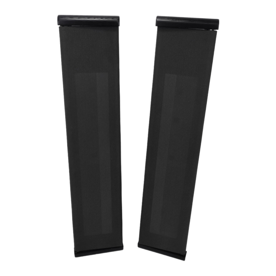
26 inches from the floor for proper high frequency dispersion when you are sitting or standing. To help determine the front of the MMC 2, the quasi ribbon foil can be seen through the fabric on the front of the speaker. The speakers should be mounted so that the front of the speakers are on axis with the listener. -
Page 3: B Painting Speaker Frames
Painting Speaker Frames Many customers will want to paint the top and bottom molding to match their decor. The top and bottom frames can be ordered with a primer coat. We recommend Krylon spray can paint. a. Mask off hardware in the speaker frames to prevent paint from fouling mechanical parts. -
Page 4: C Tips From The Pros For Do-It-Yourselfers
From the bottom frame to the baseboard, the easiest options are flat speaker wire which can be painted or hide-a-cord channels. Note, the hide-a-cord channels must be low profile to allow the MMC 2 to close completely. c. For the motor and speaker wires to have clearance between the top and bottom frames and the wall, it is necessary to route a small groove on the back of frames. -
Page 5: Revision-- 7-25-15 Page Of 8
d. Level the template by placing a level on the top or side of the template. See Fig. 2. CAUTION- Take great care to ensure that the wall is plumb (vertical) and the template is level before drilling the holes. The speakers will not close or open if severely out of plum or level. - Page 6 Fig. 1 Fig. 2 Revision-- 7-25-15 Page of...
-
Page 7: E Top Frame Installation
Top Frame Installation Thread motor wires through the 1/4" dia. center hole and attach the top frame using keyholes on the back of the top frame. If necessary, adjust the screw height to insure a snug fit of the top motor frame to the wall. See Fig. 3 & 4. ... -
Page 8: F Attaching Bottom Frame To Speaker
Attaching Bottom Frame to Speaker a. Caution-- Do not rest the weight of the speaker panel on the speaker wires. Under extreme force, the steel tube could cut through the insulation. b. Lay the speaker on a table with the bottom extending about 12" over the edge of the table. - Page 9 Fig. 6 Revision-- 7-25-15 Page of...
-
Page 10: G Bottom Frame Attachment To Wall
G Bottom Frame Attachment to Wall a. While keeping the bottom frame and speaker together, take the speaker to the wall for installation. See Fig. 7. b. Feed the speaker wire through the 1/4" dia. bottom center hole and attach the lower frame to the wall using the keyholes on the back of the bottom frame. - Page 11 Fig. 8 Fig. 9 Revision-- 7-25-15 Page...
-
Page 12: H Final Speaker Installation
H Final Speaker Installation Many of the adjustments and installation are much easier with the aid of an LED headlamp. The final step is the most difficult (and may require the help of an assistant). Slightly raise the top frame to allow clearance for the pin on the top of the speaker wheel to clear the top frame when it will be moved into position. - Page 13 Final Adjustments a. Helpful hint--Ensuring that the panel moves freely or detecting the slight resistance of the Cam/Stop is made easier if the motor assembly and drive wheel is pulled away from the idler wheel. The motor assembly can be held out of the way by attaching a 1 inch-wide piece of duct tape to the entire length of the motor frame (or with the help of an assistant).
- Page 14 Slowly move the speaker panel through it's 180 degree range of motion to check for excessive resistance. If the MMC 2 is installed correctly for plumb and level (so that the motor is not pushing the panel "uphill"...
-
Page 15: I Hookup
Hookup Connect the positive (red) speaker wire to the MMC 2 white and red wire. We recommend that the connection to the speaker wire be soldered with shrink tubing for electrical insulation. Check for correct phasing before making a permanent connection. -
Page 16: Speaker Angle Adjustment
Final Speaker Installation (or with the help of an assistant). For the best sound, the MMC 2 should be angled so that the panel is on-axis with the listener with a minimum distance from the wall of 30 degrees. (Use of the MMC 2 as a dual center channel speaker requires slightly different... - Page 17 Fig. 1 and 2 below and loosen the allen screw. Rotate the MMC 2 to the desired position as shown in Fig. 3 and 4 while holding the Cam/Stop stationary. It is necessary to raise the MMC 2 slightly to remove the weight of the speaker off...
- Page 18 Setting stop in closed position-- A nylon screw is included with the MMC 2 to act as a stop so that the MMC 2 can be adjusted to be parallel with the wall in the closed position. The screw hole is located at the bottom inside edge of the MMC 2--3/4 inch from the bottom and 1 1/8 inch from the outside edge.
- Page 19 Fig. 12 Fig. 13 Revision-- 7-25-15 Page...
- Page 20 Fig. 14 Revision-- 7-25-15 Page...
-
Page 21: K Phasing
Phasing a. Correct phasing between a "small" speaker, like the MMC 2, and the Bass Panel is much more difficult to detect than an out-of-phase condition between left and right speakers. The ear/brain is less sensitive to phase shift problems at lower frequencies and therefore, making it more difficult to detect. -
Page 22: L Bass Management And Processor Settings
MMC 2s or if a processor is being used, the processor can be set for "small" speaker. b. The lower frequency response of the MMC 2 depends, to a large degree, on the room acoustics and where the MMC 2s are used in the room. For example, a front wall placement of the MMC 2s will result in less midbass and therefore require a higher crossover point. -
Page 23: M Tweeter Level Control
M Tweeter Level Control A rocker switch is located on the back of the speaker near the top (in the crossover region). Depressing the switch to the right will give maximum high frequencies. Depressing the switch to the left will reduce the high frequencies with a 1 ohm resistor.
Need help?
Do you have a question about the MMC 2 and is the answer not in the manual?
Questions and answers