Table of Contents
Advertisement
Quick Links
Also for use in assembly of JR Ergo Quattro when combined with Ergo Quattro Suppliment Instructions.
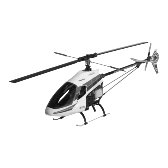
ERGO Z230 SPECIFICATIONS
Overall Length
Overall Height
Main Rotor Diameter
ASSEMBLY INSTRUCTIONS
55.85"
18.92"
60.45"
Heli Division
Tail Rotor Diameter
10.34"
Gear Ratio
6.77:1:5.18
Gross Weight
12.4 lbs.
Advertisement
Table of Contents

Related Manuals for JR ProPo Ergo Z230


Summary of Contents for JR ProPo Ergo Z230
-
Page 1: Assembly Instructions
ASSEMBLY INSTRUCTIONS Also for use in assembly of JR Ergo Quattro when combined with Ergo Quattro Suppliment Instructions. ERGO Z230 SPECIFICATIONS Overall Length 55.85" Tail Rotor Diameter 10.34" Overall Height 18.92" Gear Ratio 6.77:1:5.18 Main Rotor Diameter 60.45" Gross Weight 12.4 lbs. - Page 2 PRE-ASSEMBLY INFORMATION This kit has been both engineered and manufactured by JR with help from some Since this manual has been formatted for use in assembly of both the Ergo Z230 of Japan’s top R/C helicopter engineers (now employed by JR).
-
Page 3: Table Of Contents
INDEX Section Description Page Section Description Page Building Supplies .........5 Tail Blade Holder Assembly . - Page 4 6-channel or greater PCM R/C helicopter system with 5 servos, 1000 mAh receiver battery and gyro. Note: Due to the additional RF interference generated by the Zenoah G23 gasoline engine, it is highly recommended that only a PCM (Pulse Code Modulation) system be used with the Ergo Z230. JRXP783 PCM JRXP8103 PCM...
-
Page 5: Building Supplies
2. BUILDING SUPPLIES (NOT INCLUDED): The following items are needed to complete the assembly of the JR Ergo Z230: Gasoline Fuel Tubing Gasoline Fuel Filter Whip Antenna (AER1073) (DUB341) (RVO1010) Locktite 242 (Blue) Double Sided Servo Dubro Brass Sintered Fuel Filters (2pc) -
Page 6: Tools/Field Equipment
3. TOOLS NEEDED TO ASSEMBLE THE JR ERGO Z230 (NOT INCLUDED): Needle Nose Pliers Scissors Phillips Screwdriver Nut Drivers: 5mm, 7mm Hobby Knife Metric Ruler Drill and Drill Bits Small Hammer Sandpaper (80-100 Grit) Adjustable Pliers Allen Wrenches: 1.5, 2.0, 2.5, 3.0, 4.0mm Blade Balancer 4. -
Page 7: Hardware Identification
HARDWARE IDENTIFICATION There are a variety of sizes and shapes of hardware included in this kit. All of the hardware, screws, nuts, etc., contained in the Ergo kit are described in Prior to assembly, please be careful to identify each screw by matching it to the the following A, B, C manner: full size screw outlines included in each step. -
Page 8: Clutch Bell/Start Shaft Assembly
CLUTCH BELL/START SHAFT ASSEMBLY Starter Hex Adaptor 4x4mm Set Screw (Use Threadlock) Use Threadlock Complete Assembly ..1 pc Start Shaft Bearing Block 4x4mm Set Screw Note: These items are Be sure that the Bearing with pre-assembled the 5mm ID faces upward Pinion Gear (13T) (Use Threadlock when assembling) -
Page 9: Control Ball Installation
CONTROL BALL INSTALLATION 2x8mm Flat Head Screw 3x5x1.8mm Spacer (Use Threadlock) Use Threadlock 2mm Nut 2mm Nut 5x8x4mm Ball Bearing ..1 pc 2x8mm Flat Head Screw ..8 pc 2x10mm Flat Head Screw 2x10mm Flat Head Screw ..9 pc Steel Joint Ball ..3 pc Steel Joint Ball 2mm Nut... -
Page 10: Elevator Arm Assembly
ELEVATOR ARM ASSEMBLY ..2 pc 2x8mm Flat Head Screw ..2 pc Elevator Arm Rear Elevator Arm Front Steel Joint Ball Swashplate A Arms ..2 pc Elevator Arm Pin Steel Joint Ball Steel Joint Ball 2x8mm Flat Head Screw 2x8mm Flat Head Screw Elevator Arm Pins Caution: Be sure to note the correct installation direction of the Swashplate A Arm. -
Page 11: Fuel Tank Assembly
FUEL TANK ASSEMBLY Note: The Fuel Tank Fittings included in the Z230 kit are made specifically for gasoline use. 1. Cut the small Gasoline Tubing (included) to a length of 77mm. Next, connect the Fuel Tank Clunk, Nipple, and medium Gasoline Fuel Tubing (not included) as shown below. -
Page 12: Upper Main Frame Section Assembly
UPPER MAIN FRAME SECTION ASSEMBLY ..22 pc Use Threadlock 3x8mm Socket Head Bolt ..2 pc 3mm Lock Nut Tail Control Rod Guide ..11 pc 3mm Flat Washer Note: Due to the addition of the Frame Double Plates, only 3x6mm Socket Head Bolt four 3mm Flat Washers are ..2 pc Body Mounting Standoff... -
Page 13: Upper Main Frame Control Lever Installation
Mixing Levers/Control Arms as shown: ..1 pc 3x22mm Socket Head Bolt Note: When adjusting final control rod lengths, make sure that “JR Propo” ..1 pc moulded into the Ball Link faces outwards 3mm Lock Nut before attaching to the Steel Joint Balls. -
Page 14: Lower Main Frame Assembly
Rubber into the lower frame halves before Nut (2pc) Mounting Rubber as follows: attaching the Main Frame Standoffs. Ergo Z230: Grey (Soft) When securing Standoffs to Frame, position Ergo Quattro: Black (Hard) the bottom of the frame on a level surface to prevent twisting during tightening. -
Page 15: Front Radio Bed Installation
FRONT RADIO BED/INSTALLATION Front Radio Bed * Install the Front Radio Bed Spacer in the correct *Front Radio Bed Spacers (2pc) Use Threadlock direction as shown. Shorter Distance Front Radio Bed Spacer 3x18mm Socket Head Bolt Install the 3x25mm Set Screw into (2pc) the Body Mounting Standoffs to the correct distance as shown and... -
Page 16: Upper/Lower Main Frame Assembly Attachment
UPPER/LOWER MAIN FRAME ASSEMBLY ATTACHMENT on all Use Threadlock screws in this assembly..14 pc 3x22mm Socket Head Bolt ..7 pc Main Frame Standoff, 32mm Main Frame Spacer, 22mm (14pc) ..14 pc Main Frame Spacer, 22mm Main Frame Standoff, 32mm (7pc) 3x22mm Socket Head Bolt (14pc) -
Page 17: Main Drive Gear/Autorotation Assembly
MAIN DRIVE GEAR/AUTOROTATION ASSEMBLY 3x6mm Socket Head Bolt (4 pc) Tighten equally to prevent warping of Main Drive Gear Use Threadlock Main Drive Gear ..4 pc 3x6mm Socket Head Bolt Autorotation Assembly MAIN DRIVE GEAR/AUTOROTATION ASSEMBLY INSTALLATION Main Shaft Collar 4x4mm Set Screw (4 pc) 14mm Use Threadlock on all... -
Page 18: Landing Gear Assembly Installation
LANDING GEAR ASSEMBLY INSTALLATION 3x8mm Socket Head Bolt (4 pc) Use Threadlock ..4 pc 4x4mm Set Screw ..4 pc 3x8mm Socket Head Bolt ..4 pc Landing Gear Dampers (4 pc) 3x12mm Socket Head Bolt 4x4mm Set Screws ..4 pc (4 pc) 3mm Washer 3mm Washer (4 pc) 3x12mm Socket... -
Page 19: Clutch Assembly Attachment
CLUTCH ASSEMBLY ATTACHMENT Clutch Assembly Apply a light coating of oil or grease Use Threadlock to the bearing before installation..2pc 4x6mm Socket Head Bolt 4x6mm Socket Head Bolt (2pc) ENGINE INSTALLATION 3mm Lock Nut (4pc) ..4pc 3x15mm Socket Head Bolt ..4pc 3mm Lock Nut ..2pc... -
Page 20: Muffler Installation
MUFFLER INSTALLATION Secure the Muffler Tab to the 4x12mm 4x12mm Socket Head Bolt Socket Head Bolt as shown below. (Installed in Step 2-3) 4mm Washer (2pc) 4mm Lock Nut Use Threadlock Muffler Muffler Tab 4mm Washer (2pc) ..1pc 4mm Lock Nut 4x12mm Socket Head Bolt ..4 pc 4mm Washer... -
Page 21: Rotor Head Hub Assembly
ROTOR HEAD HUB ASSEMBLY Head Button Use Threadlock ..5 pc 3x8mm Socket Head Bolt Main Rotor Head Body 3x8mm Socket Head Bolt Main Rotor Hub 3x8mm Socket Head Bolt Phase Adjustment Ring (5 pc) (insert onto base of Main Rotor Hub) MAIN BLADE HOLDER ASSEMBLY TWO SETS REQUIRED ..2 pc... -
Page 22: Main Blade Holder/Seesaw Attachment
MAIN BLADE HOLDER/SEESAW ATTACHMENT TWO SETS REQUIRED *Note: There are two different style Dampner Rubbers included in this kit. The recessed, or hollow type is a 20 rating (soft). The solid version is Use Threadlock a 40 rating (medium) and is suggested for use with this kit..2 pc *As Dampner Rubbers (In some kits, the solid type (40 rating) Dampner Set... -
Page 23: Washout Unit Assembly
WASHOUT UNIT ASSEMBLY TWO SETS REQUIRED Washout Base 3x4.5x4mm Washer ..2 pc 3x.05x1.8mm Spacer (2pc) 3x15mm Socket Head Bolt 5x8x4mm Ball ..2 pc Bearing (4pc) 2x10mm Flat Head Screw 3x15mm Socket ..4 pc Head Bolt (2pc) 5x8x4mm Ball Bearing ..2 pc Washout Link Pin Washout Arm ..4 pc... -
Page 24: Swashplate/Washout Assembly Installation
SWASHPLATE/WASHOUT ASSEMBLY INSTALLATION WASHOUT ASSEMBLY INSTALLATION Washout Base Washout Assembly Long Flange Install onto the Mainshaft so the longer portion of the Washout Base faces downward toward the Swashplate Swashplate Assembly UPPER SWASHPLATE RING TOP VIEW OF SWASHPLATE Connect the two Washout Links to the correct Upper Swashplate Balls as shown. -
Page 25: Rotor Head Installation
ROTOR HEAD INSTALLATION Completed Rotor Head Assembly 3mm Lock Nut ..1 pc 3x26mm Socket Head Bolt (Long Shank) ..1 pc 3mm Nut 3x26mm Socket Head Bolt *Note: Be sure to use the special 3x22mm Long Shank Bolt (included in the separate screw bag) Be sure to engage the Phase Adjusting Ring Pin into the When the Main Rotor Head is secured in place, make sure the Swashplate... -
Page 26: Flybar Installation
FLYBAR INSTALLATION Flybar Control Arm (2 pc) Use Threadlock 4mm Washer (2pc) 4x4mm Set Screw (2 pc) ..2 pc 4x4mm Set Screw ..2 pc Steel Joint Ball ..2 pc 2x8mm Flat Head Screw ..2 pc Flybar 4mm Washer Note: Center the Flybar in the Seesaw Shaft before securing the two Flybar Control Arms 2x8mm Flat Head Steel Control Ball... -
Page 27: Rotor Head/Swashplate Control Rod Installation
Thread the Universal Links onto the threaded Control Rods to the lengths shown below. Please note that all links should be adjusted so that when attached to the Control Ball, the words “JR Propo” are to the outside. SEESAW ARM TO MAIN BLADE HOLDER SWASHPLATE TO ROLL BELLCRANK (2.3x15mm Threaded Rod) -
Page 28: Tail Output Shaft/Pulley Assembly
TAIL OUTPUT SHAFT/PULLEY ASSEMBLY Spring Pin Adjustable Pliers ..1 pc Spring Pin Spring Pin Tail Output Shaft Press in Spring Pin gently using adjustable pliers. Be sure to center pin through the Tail Case Pulley when completed. Longer Distance Press pin into this hole Note correct direction of Tail Output Shaft during assembly Tail Case Pulley... -
Page 29: Tail Center Hub Assembly
TAIL CENTER HUB ASSEMBLY ..2 pc 3x3mm Set Screw Use Threadlock 3x3mm Set Screw (2 pc) TWO SETS REQUIRED Tail Center Hub ..2 pc Tail Blade Holder Bearing 3mm Lock Nut Tail Slide Ring Assembly (Sealed) (2 pc) Tail Thrust Bearing ..2 pc Tail Blade Holder Bearing (Sealed) 10x7mm Washer (Large) -
Page 30: Tail Pitch Control Lever Installation
TAIL PITCH CONTROL LEVER INSTALLATION ..1 pc 2x8 Flat Head Screw ..1 pc 2x20mm Socket Head Bolt ..1 pc 2mm Flat Washer ..1 pc Steel Joint Ball ..1 pc Tail Lever Bushing Snap Tail Pitch Control Lever Onto Ball 2mm Flat Washer Steel Joint Ball Tail Lever Bushing 2x8mm Flat... -
Page 31: Tail Boom Assembly Installation
TAIL BOOM ASSEMBLY INSTALLATION Slide the Tail Boom through the Tail Boom Carrier and engage the Tail Drive Belt over the Front Pulley. Be certain to note the correct rotation (direction shown below). Set the belt tension per the directions below. Secure Bolts completely after inserting Tail Note: It may be necessary to add one thickness... -
Page 32: Tail Boom Brace Assembly
TAIL BOOM BRACE ASSEMBLY TWO SETS REQUIRED ..4 pc 2.6x12mm 2.6x12 Socket Head Bolt Socket Head Bolt Tail Brace Tube It is suggested that the Tail Brace Connectors be bonded to the Tail Brace Tubes using either thick CA Adhesive or JB Weld. 2.6x12mm Socket Head Bolt Tail Brace Connector (4 pc) 5-10... -
Page 33: Upper Servo Tray Installation
UPPER SERVO TRAY INSTALLATION Upper Servo Tray 3x8mm Socket Head Bolt (4 pc) ..4 pc 3x8mm Socket Head Bolt RADIO INSTALLATION SUGGESTIONS Be sure to install four rubber servo grommets and eyelets to each servo prior to It is suggested that both the receiver and gyro amplifier be isolated from vibration installation. -
Page 34: Servo/Switch Harness Installation
SERVO/SWITCH HARNESS INSTALLATION 2.6x12mm Self Tapping Screw 2.6mm Flat Washer Outer holes are for Futaba Servos ..20 pc 2.6x12mm Self Tapping Screw Inner holes are for JR Servos ..20 pc 2.6mm Flat Washer (4 Per Servo) * Note correct Servo Output Shaft orientation during installation. -
Page 35: Tail Control Rod Assembly
TAIL CONTROL ROD ASSEMBLY Tail Control Rod Bushings Universal Link (2 pc) ..5 pc Tail Control Rod Bushing Tail Control Rod ..2 pc Universal Link TAIL CONTROL ROD INSTALLATION Tail Contol Rod Guide (4 pc) Tail Control Rod Clip located on Main Frame Doubler Plate Note: Be sure to use the inside hole of the Tail Control Rod Guide during... -
Page 36: Gyro/Receiver/Battery Installation
GYRO/RECEIVER/BATTERY INSTALLATION *Sponge/Foam Rubber * Wrap the Receiver/Gyro Amplifier in sponge or foam rubber to Gyro Amplifier protect from vibration. Gyro Gain Controller Double Sided Servo Tape Receiver *Revolution 1010 Base Loaded Whip Antenna Double Sided Servo Tape Ni-Cad Rx Battery Pack (1000-1100ma minimum) **Gyro Unit *Note: Due to the additional RF interference generated by the Zenoah G23... -
Page 37: Radio System Preparation
RADIO SYSTEM PREPARATION The following preparations are suggested for use with JR radio systems. However, these procedures are applicable to most other brand radio systems. These suggested adjustments are necessary to insure correct installation and attachment of the control linkages and servo horns. TRANSMITTER PREPARATION Set all trim levers, trim knobs and switches to the neutral or zero to another model, reset all functions and input values to the factory preset... -
Page 38: Aileron Linkages
AILERON LINKAGES Note: Attach the Steel Joint Ball to the correct hole as shown below: ..1 pc Servo Horn 2x8mm Flat Head Screw Use Threadlock 2x8mm Flat Head Screw ..1 pc Steel Joint Ball Steel Joint Ball ..1 pc 2mm Hex Nut 2mm Hex Nut Make sure the Aileron Trim is in the... -
Page 39: Collective Pitch Linkages
COLLECTIVE PITCH LINKAGES Note: Attach the Steel Joint Ball to the correct hole as shown below: Servo Reversing Directions Reverse 2x8mm Flat Head Screw 90° (Use Threadlock) Futaba Reverse Use Threadlock High Pitch Pitch Note: Make certain the Collective Steel Joint Ball Servo is in the neutral or hover position before Servo Horn... -
Page 40: Throttle Linkage Installation
THROTTLE LINKAGE INSTALLATION 2.3x50mm Threaded Rod 2x8mm Flat Head Screw Servo Horn Steel Joint Ball 37mm Use Threadlock ..1 pc 2mm Hex Nut 2x8mm Flat Head Screw 38mm Futaba ..1 pc Steel Joint Ball ..1 pc 2mm Hex Nut High Servo Reversing Directions Reverse Futaba... -
Page 41: Control Lever/Linkage Adjustment
CONTROL LEVER/LINKAGE ADJUSTMENT To Servos Note: The following adjustments are made with all Servo Mixing Arms servos in the center (1/2 stick) or neutral positions. Check to insure that both the Elevator (2) and Aileron (1) Servo Mixing Arms are parallel (same angle) to the Mixing Mixing Base Arms Base Arms (2) with all servos in the neutral (center) positions. -
Page 42: Body Assembly/Canopy Attachment
BODY ASSEMBLY/CANOPY ATTACHMENT * After trimming, attach the canopy to the body temporarily with tape. Next drill five 1/16" holes through both the canopy and the body and secure using the 2.3x8mm screws provided..6 pc 2.3x8mm Self Tapping Screw ..4 pc Rubber Grommets (4pc) Rubber Grommets... -
Page 43: Decal Placement
DECAL PLACEMENT... -
Page 44: Main Rotor Blade Assembly
MAIN ROTOR BLADE ASSEMBLY Blade Weight Installation It is suggested that the root and tip of each blade be Using 80-100 grit sandpaper, sand the blade sealed prior to covering. We suggest either thick CA weight strip (2) to produce a roughened surface. or Aero Gloss clear dope for this task. -
Page 45: Main Rotor Blade Final Balancing
MAIN ROTOR BLADE FINAL BALANCING Main Rotor Blades Step 1 Step 2 Drinking Glass (2 pc) Spanwise C.G. Balancing Final Static Balancing Place each rotor blade on a sharp edge of a table as To static balance the main rotor blades, it is suggested to either attach each blade to a “seesaw”... -
Page 46: Final Servo Adjustment And Radio Set Up
It is suggested that the correct neutral settings be achieved without the *Note: To achieve these pitch range settings with the Ergo Z230, it will be use of the sub-trim feature. If sub-trim is used for final flight necessary to install the optional Seesaw Mixing Arms (JRP960178) adjustments, it is not suggested that the sub-trim values exceed 10. - Page 47 Hovering Throttle Stunt & Aerobatic 3D Flight (Optional) Curve Flight (normal) Power (Output) Power (Output) Power (Output) 100% 100% 100% 100% Flight Mode 2 Flight Mode Flight Mode 0% Idle 0% Idle Stick/Point Positions Stick/Point Positions Stick/Point Positions (input) (input) (input) Note: The throttle curve examples shown correspond to the pitch curve examples show in Step 6A on the...
-
Page 48: Data Sheets
XP783 DATA SHEET MODEL NO. ERGO Z230, QUATTRO (INITIAL SET-UP) MODEL NAME ERGO Z230, Quattro MODULATION S-PCM • Z-PCM • PPM AUTO AILE ELEV RUDD ST-1 INH • ACT 90 % 70 % (POS.1) ST-2 INH • ACT D/R • R... - Page 49 XP8103 DATA SHEET MODEL NO. ERGO Z230, QUATTRO (INITIAL SET-UP) MODEL NAME ERGO Z230, Quattro MODULATION S-PCM • Z-PCM • PPM AILE ELEV RUDD INH • ACT AUTO INH • ACT (POS. 1) DUAL-RATE INH • ACT • 100% 100%...
- Page 50 MODEL NO. (84) _____________________________________ PCM-10SX DATA SHEET ERGO Z230, QUATTRO (INITIAL SET-UP) MODEL NAME (81) ERGO Z230, Quattro MODULATION (85) SPCM-ZPCM-PPM THRO AILE ELEV RUDD GEAR PITCH AUX2 AUX3 AUX4 AUX5 REVERSE SW (11) Adjust for L 100% D 100%...
-
Page 51: Data Sheets
PCM-10SX DATA SHEET ERGO Z230, QUATTRO (INITIAL SET-UP) CONTINUED — — — — 50% Power — — 100% Power • — — HOV.SEL THRO — — • CURVE 100% Power % Power — 60% Power — (18) — — •... -
Page 52: Final Pre-Flight Check
FINAL PRE-FLIGHT CHECK Once all assemblies have been completed, please review the following and that each servo horn is secured with a servo horn mounting screw. suggestions before attempting initial flights. • Verify that the gyro is operational and compensating in the correct direction (detailed in Step 8, page 47). -
Page 53: Range Test/Initial Engine Start-Up & Adjustment
PCM (Pulse Code Modulation) radio system be used heavy cloth. DO NOT use your cleaning cloth as it may be contaminated with the Ergo Z230. with gasoline. If fire continues, call for help. Range Testing: Engine Off Initial range testing should be performed per the radio manufacturers suggested antenna down range requirements. - Page 54 RPM and power output is established. Zenoah G23. Once this has been achieved, continue to fly the Ergo Z230 in forward flight Although the Zenoah G23 is a 2 cycle engine, the smoke levels emitted by the while monitoring the engines power output levels. If during the flight the engine exhaust are much less than with most common 2 cycle glow engine.
-
Page 55: General Maintenance
GENERAL MAINTENANCE Engine If there is excessive play noted, replace the universal link in question. After each day of flying, fully drain the fuel tank. Then start the engine and let it idle until the engine and the fuel line are completely burned off. Battery Maintenance Check to insure that your batteries are properly mounted and charged. - Page 56 ROTOR HEAD/SWASHPLATE/WASHOUT ASSEMBLY 980052 980013 970098 960189 960195 960179 960180 980074 980013 970004 960176 960181 981026 970098 980052 980030 980044 970069 970101 960177 960194 970093 970115 980044 970069 970077 980039 970004 981026 960182 960258 981027 970001 980016 980074 980037 960013 960179 970095 980004...
-
Page 57: Rotor Head/Swashplate/Washout Assembly Parts List
ROTOR HEAD/SWASHPLATE/WASHOUT ASSEMBLY PARTS LIST PART # DESCRIPTION QUANTITY COMMENTS /ADDITIONAL CONTENTS 960013 Washout Base 960014 Swashplate Assembly 3 - 2x8mm Flat Head Screws 4 - 2x10mm Flat Head Screws 7 - Steel Joint Balls 960153 Flybar Paddles 960176 Blade Holder Spacer, Silver 960177 Seesaw Shaft 2 - 3x5mm Button Head Cap Screws... - Page 58 CYCLIC MIXING ARMS/ELEVATOR/AILERON CONTROL ARMS 980049 960020 970001 970082 960022 980013 960021 970001 970016 981031 970017 970016 970119 981031 960261 980013 980037 970001 960264 970004 980039 980087 980019 970004 970002 980012 980085 981031 981030 970115 970002 970004 980050 980086 970115 980046 970002 981031...
-
Page 59: Cyclic Mixing Arms/Elevator/Aileron Control Arms Parts List
CYCLIC MIXING ARMS/ELEVATOR/AILERON CONTROL ARMS PARTS LIST PART # DESCRIPTION QUANTITY COMMENTS /ADDITIONAL CONTENTS 960020 Elevator Arm: Front Complete w/Bushing Steel Joint Ball 2x8mm Flat Head Screw 960021 Elevator Arm: Rear Complete w/Bushing Steel Joint Ball 2x8mm Flat Head Screw 960022 Swashplate A Arm Complete w/2 A-Arm Pins... - Page 60 START SHAFT/CLUTCH/ENGINE ASSEMBLY 960190 980012 960005 980036 980004 981006 981025 960018 980036 980013 960157 981005 970125 960256 980013 970096 960257 960018 980040 970118 980062 970127 960259 980013 980071 980098 980099 980062 980062 970050 960253 960254 970052 980039 960250 980064 980071 980071 980063 980071...
-
Page 61: Start Shaft/Clutch/Engine Assembly Parts List
START SHAFT/CLUTCH/ENGINE ASSEMBLY PARTS LIST PART # DESCRIPTION QUANTITY COMMENTS /ADDITIONAL CONTENTS 960005 Starter Hex Adaptor Complete w/One 4x4mm Set Screw 960018 Tail Drive Pinion Bearing Block Complete w/Bearing 960157 Start Shaft Bearing Block Complete w/Bearings 960190 Front Tail Belt Pulley Complete w/One 3x6mm Socket Head Bolt 1 - 3mm Washer 960250... -
Page 62: Upper Main Frame/Radio Tray/Body Set Parts List
UPPER MAIN FRAME/RADIO TRAY/BODY SET ASSEMBLY PARTS LIST 982012 982020 960072 980025 980004 970008 970035 960262 980013 980096 970020 980013 970122 970035 970122 960017 970020 960192 980035 970122 981013 980027 960002 980012 960252 960031 980004 980026 960251... - Page 63 2 - 19mm x 10mm x 7mm Bearings 981013 C Stopper Ring 982012 Ergo Z230/Quattro Canopy 6 - 2.3x8mm Self Tapping Screws 960270 Ergo Z230/Quattro Decal Set 982020 Ergo Z230/Quattro Body Set 4 - Rubber Grommets 6 - 2.3x8mm Self Tapping Screws...
- Page 64 980069 970117 960255 980013 960266 970124 980069 980063 980026 970025 980100 970126 980071 970126 960031 960191 980101 980081 Ergo Z230 960267 980069 980013 980018 980066 970097 980069 980014 970106 960260 960269 960183 Ergo Quattro 960273 980013 960117 960118 960120 980004...
-
Page 65: Lower Main Frame/Landing Gear/Fuel Tank Parts List
960266 Front Radio Bed 960267 Lower Frame Angles Z230 Quattro 960269 Fuel Tank Set Ergo Z230 1 - Fuel Tank 1 - Fuel Tank 1 - Fuel Stopper 1 - Fuel Stopper 960273 Fuel Tank Set Ergo Quattro 1 - Tank Grommet... -
Page 66: Tail Boom/Tail Brace/Tail Boom Carrier Parts List
TAIL BOOM/TAIL BRACE/TAIL BOOM CARRIER PARTS LIST 983005 960048 980014 960047 980039 980016 960197 980039 960186 980015 980024 980022 980013 983010 960048 980084 980036 980088 960047 960044 983011 983006 980009 970117 980014 980036... - Page 67 TAIL BOOM/TAIL BRACE/TAIL BOOM CARRIER PARTS LIST PART # DESCRIPTION QUANTITY COMMENTS /ADDITIONAL CONTENTS 960044 Tail Brace Connector 1 - 2.6x12mm Socket Head Bolt 960047 Tail Brace Tube 960047 Tail Boom Carrier 2 - 3x40mm Socket Head Bolts 4 - 3x15mm Socket Head Bolts 6 - 3mm Lock Nuts 960048 Tail Rod Guide Set...
- Page 68 TAIL CASE/TAIL BLADE HOLDERS/TAIL PITCH PLATE 960129 960127 980006 970002 960128 980070 960056 960050 981018 960058 960057 970028 981019 980037 970065 980016 970054 980029 981020 980039 981004 960188 970027Z 980089 980078 960187 981004 970001 980034 960054 980008 960185 ASSEMBLY INSTRUCTIONS 980038 960271 960197...
-
Page 69: Tail Case/Tail Blade Holders/Tail Pitch Plate Parts List
960056 Tail Pitch Link Complete w/2 Link Pins 960057 Tail Pitch Plate 960058 Tail Slide Ring Complete w/Bearing 960271 Ergo Z230 Assembly Manual 960127 Tail Center Hub 960128 Tail Blade Holder Set 1 Set 960129 Tail Rotor Blades 960185 Tail Case Set (L&R) 6 - 2.6x10mm Socket Head Bolts... -
Page 70: Zenoah G23 Engine Service/Information Parts
ZENOAH G23 ENGINE SERVICE/PARTS INFORMATION Warranty Information Zenoah G23 Helicopter Engine Parts Listing Your Zenoah G23 engine is warranteed for 3 years against defects in parts and Item # Part Description workmanship. This warranty does not cover damages occurred in a crash, or from 19821 Crankcase Assembly Bolt improper use and tuning resulting in damage to the engine. - Page 72 Heli Division Exclusively distributed by Horizon Hobby Distributors 4105 Fieldstone Road Champaign, IL 61821...
Need help?
Do you have a question about the Ergo Z230 and is the answer not in the manual?
Questions and answers