
Related Manuals for JR ProPo Ergo


Summary of Contents for JR ProPo Ergo
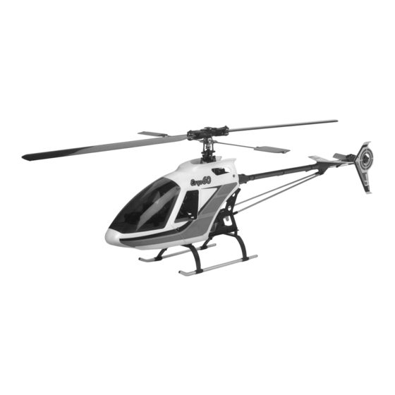
- Page 1 .60 ASSEMBLY INSTRUCTIONS ERGO SPECIFICATIONS Overall Length 55.85" Tail Rotor Diameter 10.34" Overall Height 18.92" Gear Ratio 9.78:1:5.18 Main Rotor Diameter 60.45" Gross Weight 10.58 lbs. Heli Division...
- Page 2 JR now brings this reputation and knowledge into the helicopter market with the PRE-ASSEMBLY INFORMATION development of the Ergo and the organization of the JR heli division. Years in the making, the Ergo’s superior quality and exceptional parts fit and finish create a When first opening your Ergo kit, you will notice that all of the parts are new standard of quality that was previously unavailable.
-
Page 3: Table Of Contents
INDEX Section Description Page Section Description Page Tools ..........6 Tail Blade Holder Assembly . - Page 4 Make assembly trouble free and enjoyable. Self-Aligning One-Piece Steel Clutch System Offers easy installation and adjustment with exceptional reliability. ITEMS REQUIRED TO COMPLETE THE JR ERGO (not supplied in kit) 1. RADIO SYSTEM REQUIREMENTS (NOT INCLUDED): 6-channel or greater R/C helicopter system with 5 servos, 1000 mAh receiver battery and gyro.
- Page 5 (Webra .61 Heli Engine Shown) (Thunder Tiger Pro .61 Heli Engine Shown) WEBE675 TTR9695 3. BUILDING SUPPLIES (NOT INCLUDED): The following items are needed to complete the assembly of the JR Ergo: Silicone Fuel Tubing Fuel Filter Whip Antenna Glow Plugs...
-
Page 6: Tools
4. TOOLS NEEDED TO ASSEMBLE THE JR ERGO .60 (NOT INCLUDED): Nut Drivers: 5mm, 7mm Needle Nose Pliers Scissors Phillips Screwdriver Drill and Drill Bits Small Hammer Hobby Knife Metric Ruler Blade Balancer Adjustable Pliers Sandpaper (80-100 Grit) Allen Wrenches: 1.5, 2.0, 2.5, 3.0, 4.0mm 5. -
Page 7: Hardware Identification
There are a variety of sizes and shapes of hardware included in this kit. All of the hardware, screws, nuts, etc., contained in the Ergo kit are described in Prior to assembly, please be careful to identify each screw by matching it to the the following A, B, C manner: full size screw outlines included in each step. -
Page 8: Clutch Bell/Start Shaft Assembly
CLUTCH BELL/START SHAFT ASSEMBLY Starter Hex Adaptor Use Threadlock 4x4mm Set Screw (Use Threadlock) ..1 pc Complete Assembly Start Shaft Bearing Block 4x4mm Set Screw Be sure that the Bearing with the 5mm ID faces upward Pinion Gear (Use Threadlock when assembling) Start Shaft Clutch Bell Assembly... -
Page 9: Control Ball Installation
CONTROL BALL INSTALLATION 2x8mm Flat Head Screw Mixing Lever (3 pc) (Use Threadlock) (Prepare 3 Sets) Use Threadlock ..1 pc 2mm Nut Roll Bell Crank 2x8mm Flat Head Screw Steel Joint Ball ..8 pc 2mm Nut Steel Joint Ball 2x10mm Flat Head Screw ..9 pc Steel Joint Ball ..3 pc... -
Page 10: Elevator Arm Assembly
ELEVATOR ARM ASSEMBLY ..2 pc 2x8mm Flat Head Screw ..2 pc Elevator Arm Rear Elevator Arm Front Steel Joint Ball Swashplate A Arms ..2 pc Elevator Arm Pin Steel Joint Ball Steel Joint Ball 2x8mm Flat Head Screw 2x8mm Flat Head Screw Elevator Arm Pins Caution: Be sure to note the correct installation direction of the Swashplate A Arm. -
Page 11: Fuel Tank Assembly
FUEL TANK ASSEMBLY 1. Cut the small Silicone Fuel Tubing (included) to a length of 77mm. Next, connect the Fuel Tank Clunk, Nipple, and medium Silicone Fuel Tubing (not included) as shown below. 77mm Fuel Tank Clunk Silicone Tube (Small) Nipple Silicone Fuel Tubing (not included) Medium Silcone Fuel Tubing (not included) -
Page 12: Upper Main Frame Section Assembly
UPPER MAIN FRAME SECTION ASSEMBLY ..21 pc Use Threadlock 3x8mm Socket Head Bolt ..1 pc Tail Control Rod Guide 3x10mm Socket Head Bolt ..11 pc 3mm Flat Washer 3x10mm Socket Head Bolt ..2 pc Body Mounting Standoff Body Mounting Standoff: Short ..4 pc Bearing side must face upward 2.6x8mm Self Tapping Screw... -
Page 13: Upper Main Frame Control Lever Installation
UPPER MAIN FRAME CONTROL LEVER INSTALLATION Use Threadlock Nylon Washer Elevator Arm Bushing Elevator Arm Bushing Nylon Washer Note: Be sure to install the Elevator 3x8mm Socket Arm Units in their proper Head Bolt location as there is a “Front” 3mm Lock Nut Nylon Washer and a “Rear”... -
Page 14: Lower Main Frame Assembly
LOWER MAIN FRAME ASSEMBLY 2.6x8mm Self Tapping Screw Lower Main Frame Use Threadlock (2 pc) Note: In some kits, the correct 3mm Lock Nut 42mm body mounting (8 pc) standoffs may be located in a separate package. 2.6x8mm Self Tapping Screw ..10 pc 3x8mm Socket Head Bolt ..8 pc... -
Page 15: Front Radio Bed/Gyro Mounting Plate Installation
FRONT RADIO BED/GYRO MOUNTING PLATE INSTALLATION Front Radio Bed ..4 pc 3x10mm Socket Head Bolt 3x10mm Socket Head Bolt (4 pc) COOLING FAN SHROUD INSTALLATION Cooling Fan Shroud ..4 pc 3x8mm Self Tapping Screw 3x8mm Self Tapping Screw 3x8mm Self Tapping Screw... -
Page 16: Upper/Lower Main Frame Assembly Attachment
UPPER/LOWER MAIN FRAME ASSEMBLY ATTACHMENT on all Use Threadlock screws in this assembly..14 pc 3x25mm Socket Head Bolt ..7 pc Main Frame Standoff, 32mm ..14 pc Main Frame Spacer, 14mm Note: Use Threadlock on all screws in this assembly Mainframe Standoff, 32mm (7 pc) Mainframe Spacer, 14mm (14 pc) 3x25mm Socket Head Bolt (14 pc) -
Page 17: Main Drive Gear/Autorotation Assembly
MAIN DRIVE GEAR/AUTOROTATION ASSEMBLY 3x6mm Socket Head Bolt (4 pc) Tighten equally to prevent warping of Main Drive Gear) Use Threadlock Main Drive Gear ..4 pc 3x6mm Socket Head Bolt Autorotation Assembly MAIN DRIVE GEAR/AUTOROTATION ASSEMBLY INSTALLATION Main Shaft Collar Use Threadlock 4x4mm Set Screw (4 pc) ..4 pc... -
Page 18: Landing Gear Assembly Installation
LANDING GEAR ASSEMBLY INSTALLATION 3x8mm Socket Head Bolt (4 pc) Use Threadlock ..4 pc 4x4mm Set Screw ..4 pc 3x8mm Socket Head Bolt ..4 pc Landing Gear Dampers (4 pc) 3x12mm Socket Head Bolt ..4 pc 3mm Washer 4x4mm Set Screws (4 pc) 3x12mm Socket Head Bolt (4 pc) -
Page 19: Engine Mount Attachment
ENGINE MOUNT ATTACHMENT Engine Mount ..4 pc Use Threadlock 4x15mm Socket Head Bolt ..4 pc 4mm Washer Double Holes Single Holes Up OS Enya Engines BOTTOM Webra/YS Engines It is important to note the proper direction the Motor 4mm Washers (4 pc) Mount is installed to achieve the correct alignment 4x15mm Socket for the specific engine to be used. -
Page 20: Engine Installation (All)
ENGINE INSTALLATION Use Threadlock 4mm Washer (6 pc) ..6 pc 4x12mm Socket Head Bolt 4x12mm Socket Head Bolt (6 pc) ..6 pc 4mm Washer @ @ @ @ @ @ @ @ e ? @ @ @ @ @ @ @ @ e ? @ @ @ @ @ @ @ @ ? e @ @ @ @ @ @ @ @ e ? @ @ @ @ @ @ @ @ ? e @ @ @ @ @ @ @ @ e ? @ @ @ @ @ @ @ @ ? e @ @ @ @ @ @ @ @ e ? @ @ @ @ @ @ @ @ ? e @ @ @ @ @ @ @ @ e ? @ @ @ @ @ @ @ @ ? e @ @ @ @ @ @ @ @ e ? @ @ @ @ @ @ @ @ ? e @ @ @ @ @ @ @ @ e ? @ @ @ @ @ @ @ @ @ @ @ @ @ @ @ @ e ? @ @ h ? -
Page 21: Rotor Head Hub Assembly
ROTOR HEAD HUB ASSEMBLY Use Threadlock 3x8mm Socket Head Bolt ..5 pc 3x8mm Socket Head Bolt Head Button 3x8mm Socket Head Bolt Main Rotor Head Body (5 pc) Phase Adjustment Ring (insert onto base of Main Rotor Hub) Main Rotor Hub MAIN BLADE HOLDER ASSEMBLY TWO SETS REQUIRED Main Blade Holder Bearing... -
Page 22: Main Blade Holder/Seesaw Attachment
MAIN BLADE HOLDER/SEESAW ATTACHMENT TWO SETS REQUIRED Use Threadlock ...2 pc 5x10mm Socket Head Bolt *As Dampner Rubbers will wear during use, Blade Spindle Shaft check regularly and replace when necessary. * Dampner Rubber ..2 pc Thrust Bearing Silver Grip Spacer Thrust Bearing ..2 pc Spindle Washer (Black) -
Page 23: Washout Unit Assembly
WASHOUT UNIT ASSEMBLY TWO SETS REQUIRED * When installing, be careful not to over tighten..2 pc 3x15mm Socket Head Bolt Washout Base Nylon Washer ..2 pc 2x10mm Flat Head Screw ..2 pc 3mm Washer 3mm Washer ..4 pc *3x15mm Socket Head Bolt Nylon Washer (2 pc) ..2 pc... -
Page 24: Swashplate/Washout Assembly Installation
SWASHPLATE/WASHOUT ASSEMBLY INSTALLATION WASHOUT ASSEMBLY INSTALLATION Washout Base Washout Assembly Long Flange Install onto the Mainshaft so the longer portion of the Washout Base faces downward toward the Swashplate Swashplate Assembly UPPER SWASHPLATE RING TOP VIEW OF SWASHPLATE Connect the two Washout Links to the correct Upper Swashplate Balls as shown. -
Page 25: Rotor Head Installation
ROTOR HEAD INSTALLATION Completed Rotor Head Assembly 3mm Lock Nut ..1 pc 3x22mm Socket Head Bolt (Long Shank) ..1 pc 3mm Nut *Note: Be sure to use the special 3x22mm Long Shank Bolt 3x22mm Socket Head Bolt (included in the separate screw bag) Be sure to engage the Phase Adjusting Ring Pin into the When the Main Rotor Head is secured in place, make sure the Swashplate... -
Page 26: Flybar Installation
FLYBAR INSTALLATION Flybar Control Arm (2 pc) Use Threadlock 4x4mm Set Screw (2 pc) ..2 pc 4x4mm Set Screw ..2 pc Steel Joint Ball ..2 pc 2x8mm Flat Head Screw Flybar Note: Center the Flybar in the Seesaw Shaft before securing the two Flybar Control Arms 2x8mm Flat Head Steel Control Ball... -
Page 27: Rotor Head/Swashplate Control Rod
Thread the Universal Links onto the threaded Control Rods to the lengths shown below. Please note that all links should be adjusted so that when attached to the Control Ball, the words ”JR Propo“ are to the outside. SEESAW ARM TO MAIN BLADE HOLDER SWASHPLATE TO ROLL BELLCRANK (2.3x15mm Threaded Rod) -
Page 28: Tail Output Shaft/Pulley Assembly
TAIL OUTPUT SHAFT/PULLEY ASSEMBLY ..1 pc Spring Pin Adjustable Pliers Spring Pin Spring Pin Tail Output Shaft Press in Spring Pin gently using adjustable pliers. Be sure to center pin through the Tail Case Pulley when completed. Longer Distance Press pin into this hole Note correct direction of Tail Output Shaft during assembly Tail Case Pulley... -
Page 29: Tail Center Hub Assembly
TAIL CENTER HUB ASSEMBLY ..2 pc 3x3mm Set Screw Use Threadlock 3x3mm Set Screw (2 pc) TWO SETS REQUIRED Tail Center Hub ..2 pc Tail Blade Holder Bearing 3mm Lock Nut Tail Slide Ring Assembly (Sealed) (2 pc) Tail Thrust Bearing ..2 pc Tail Blade Holder Bearing (Sealed) 10x7mm Washer (Large) -
Page 30: Tail Pitch Control Lever Installation
TAIL PITCH CONTROL LEVER INSTALLATION ..1 pc 2x8 Flat Head Screw ..1 pc 2x20mm Socket Head Bolt ..1 pc 2mm Flat Washer ..1 pc Steel Joint Ball ..1 pc Tail Lever Bushing Snap Tail Pitch Control Lever Onto Ball 2mm Flat Washer Steel Joint Ball Tail Lever Bushing 2x8mm Flat... -
Page 31: Tail Boom Assembly Installation
TAIL BOOM ASSEMBLY INSTALLATION Slide the Tail Boom through the Tail Boom Carrier and engage the Tail Drive Belt over the Front Pulley. Be certain to note the correct rotation (direction shown below). Set the belt tension per the directions below. Secure Bolts completely after inserting Tail Note: It may be necessary to add one thickness... -
Page 32: Tail Boom Assembly Installation
TAIL BOOM ASSEMBLY INSTALLATION TWO SETS REQUIRED ..4 pc 2.6x12mm 2.6x12 Socket Head Bolt Socket Head Bolt Tail Brace Tube 2.6x12mm Socket Head Bolt Tail Brace Connector (4 pc) 5-10 TAIL BOOM BRACE/HORIZONTAL FIN INSTALLATION For easy installation, insert these two nuts into the Horizontal Fin/Brace Clamp first. -
Page 33: Upper Servo Tray Installation
UPPER SERVO TRAY INSTALLATION Upper Servo Tray 3x8mm Socket Head Bolt (4 pc) ..4 pc 3x8mm Socket Head Bolt RADIO INSTALLATION SUGGESTIONS Be sure to install four rubber servo grommets and eyelets to each servo prior to It is suggested that both the receiver and gyro amplifier be isolated from vibration installation. -
Page 34: Servo/Switch Harness Installation
SERVO/SWITCH HARNESS INSTALLATION Outer holes are for Futaba Servos 2.6mm Flat Washer 2.6x12mm Self Tapping Screw ..20 pc 2.6x12mm Self Tapping Screw ..20 pc 2.6mm Flat Washer (4 Per Servo) Inner holes are for JR Servos * Note correct Servo Output Shaft orientation during installation. -
Page 35: Tail Control Rod Assembly
TAIL CONTROL ROD ASSEMBLY Tail Control Rod Bushings Universal Link (2 pc) ..5 pc Tail Control Rod Bushing Tail Control Rod ..2 pc Universal Link TAIL CONTROL ROD INSTALLATION Tail Contol Rod Guide (4 pc) Tail Control Rod Clip located on Main Fram Note: Be sure to use the inside hole of the Tail Control Rod Guide during assembly. -
Page 36: Gyro/Receiver/Battery Installation
GYRO/RECEIVER/BATTERY INSTALLATION * Wrap the Receiver/Gyro Amplifier Gyro Gain Controller in sponge or foam rubber to *Sponge/Foam Rubber protect from vibration. Gyro Amplifier Double Sided Servo Tape Receiver Double Sided Servo Tape Ni-Cad Rx Battery Pack **Gyro Unit Double Sided Servo Tape Note: Double Sided Servo Tape and ** Be certain when installing the Gyro Unit to the Front Radio Tray that it... -
Page 37: Radio System Preparation
RADIO SYSTEM PREPARATION The following preparations are suggested for use with JR radio systems. However, these procedures are applicable to most other brand radio systems. These suggested adjustments are necessary to insure correct installation and attachment of the control linkages and servo horns. TRANSMITTER PREPARATION Set all trim levers, trim knobs and switches to the neutral or zero to another model, reset all functions and input values to the factory preset... -
Page 38: Aileron Linkages
AILERON LINKAGES A Special Note To Beginners: It is suggested that the maximum travel Note: Attach the Steel Joint Ball to the limits for Aileron, Elevator, Pitch and Rudder controls be reduced to 70%. correct hole as shown below: ..1 pc 2x8mm Flat Head Screw Servo Horn 2x8mm Flat Head Screw... -
Page 39: Collective Pitch Linkages
COLLECTIVE PITCH LINKAGES Note: Attach the Steel Joint Ball to the Note: Make certain the Collective correct hole as shown below: Servo Reversing Directions Servo is in the neutral or hover Reverse 2x8mm Flat Head Screw 90° position before securing the (Use Threadlock) Futaba Reverse... -
Page 40: Throttle Linkage Installation (All)
THROTTLE LINKAGE INSTALLATION (ALL) 2x8mm Flat Head Screw ..1 pc Use Threadlock 2x8mm Flat Head Screw Steel Joint Ball Servo Horn ..1 pc Steel Joint Ball 2mm Hex Nut ..1 pc 2mm Hex Nut Servo Reversing Directions Reverse High Futaba Reverse Throttle Throttle... -
Page 41: Control Lever/Linkage Adjustment
CONTROL LEVER/LINKAGE ADJUSTMENT Note: The following adjustments are made with all servos in the center (1/2 stick) or neutral positions. Check to insure that both the Elevator (2) and Aileron (1) Servo Mixing Arms are parallel (same angle) to the Mixing To Servos Servo Mixing Arms Base Arms (2) with all servos in the neutral (center) positions. -
Page 42: Body Assembly/Canopy Attachment
BODY ASSEMBLY/CANOPY ATTACHMENT Cut and Remove Rubber Grommets (4 pc) as shown 100mm Remove Body *Canopy (trim prior to attachment) 2.3x8mm Self Tapping Screw (6 pc) Trim the bottom of the Body as shown ..6 pc 2.3x8mm Self Tapping Screw Drill four 15/64"... -
Page 43: Decal Placement
DECAL PLACEMENT... -
Page 44: Main Rotor Blade Assembly
MAIN ROTOR BLADE ASSEMBLY Blade Weight Installation It is suggested that the root and tip of each blade be Using 80-100 grit sandpaper, sand the blade sealed prior to covering. We suggest either thick CA weight strip (2) to produce a roughened surface. or Aero Gloss clear dope for this task. -
Page 45: Main Rotor Blade Final Balancing
MAIN ROTOR BLADE FINAL BALANCING Main Rotor Blades Step 1 Step 2 Drinking Glass (2 pc) Spanwise C.G. Balancing Final Static Balancing Place each rotor blade on a sharp edge of a table as To static balance the main rotor blades, it is suggested to either attach each blade to a “seesaw”... -
Page 46: Servo Adjustment And Radio Set Up
It is suggested that the correct neutral settings be achieved without the *Note: To achieve these pitch range settings with the Ergo .60, it will be use of the sub-trim feature. If sub-trim is used for final flight necessary to adjust the collective linkage slightly at the Seesaw Arm adjustments, it is not suggested that the sub-trim values exceed 10. - Page 47 B. Throttle Curve Settings Below are several examples of possible throttle curves during various flight conditions. Since throttle curves can vary greatly due to engine and muffler combinations, it will be necessary to fine tune and adjust these values during test flights to achieve a constant main rotor RPM. Stunt &...
-
Page 48: Data Sheets
XP783 DATA SHEET MODEL NO. ERGO .60 (INITIAL SET-UP) MODEL NAME ERGO .60 MODULATION S-PCM • Z-PCM • PPM AILE ELEV RUDD AUTO ST-1 INH • ACT 90 % 70 % (POS.1) ST-2 INH • ACT D/R • R 100%... - Page 49 XP8103 DATA SHEET MODEL NO. ERGO .60 (INITIAL SET-UP) MODEL NAME ERGO .60 MODULATION S-PCM • Z-PCM • PPM AILE ELEV RUDD INH • ACT AUTO INH • ACT (POS. 1) DUAL-RATE INH • ACT • 100% 100% 100% AUX2 HOLD SW•...
- Page 50 MODEL NO. (84) _____________________________________ PCM-10SX DATA SHEET ERGO .60 (INITIAL SET-UP) MODEL NAME (81) ERGO .60 MODULATION (85) SPCM-ZPCM-PPM THRO AILE ELEV RUDD GEAR PITCH AUX2 AUX3 AUX4 AUX5 REVERSE SW (11) Adjust for L 100% D 100% L 150%...
-
Page 51: Data Sheets
PCM-10SX DATA SHEET ERGO .60 (INITIAL SET-UP) CONTINUED 50% Power 100% Power • —— —— HOV.SEL THRO • CURVE 100% Power 40% Power 50% Power (18) • 100% Power 50% Power 100% Power TH,TRIM=SLOW HOV.T=CENTER • • -2° Pitch 5° Pitch 10°... -
Page 52: Final Pre-Flight Check
FINAL PRE-FLIGHT CHECK Once all assemblies have been completed, please review the following and that each servo horn is secured with a servo horn mounting screw. suggestions before attempting initial flights. • Verify that the gyro is operational and compensating in the correct direction (detailed in Step 8, page 47). -
Page 53: General Maintenance
GENERAL MAINTENANCE Engine Check to insure that all universal links fit freely but securely to the control balls. After each day of flying, fully drain the fuel tank. Then start the engine If there is excessive play noted, replace the universal link in question. and let it idle until the engine and the fuel line are completely burned off. - Page 54 ROTOR HEAD/SWASHPLATE/WASHOUT ASSEMBLY 980052 980013 970098 980017 980049 960189 960195 970013 960179 980036 960180 980074 980013 970004 960176 960184 960181 981026 970098 980030 980052 980044 970069 970101 960177 970029 960194 970002 970093 980044 970069 981026 970077 980070 970004 960182 981027 960178 980074 960013...
-
Page 55: Rotor Head/Swashplate/Washout Assembly Parts List
ROTOR HEAD/SWASHPLATE/WASHOUT ASSEMBLY PARTS LIST PART # DESCRIPTION QUANTITY COMMENTS /ADDITIONAL CONTENTS 960012 Washout Assembly Complete w/all Components 960013 Washout Base 960014 Swashplate Assembly 3 - 2x8mm Flat Head Screws 4 - 2x10mm Flat Head Screws 7 - Steel Joint Balls 960153 Flybar Paddles 983008... - Page 56 CYCLIC MIXING ARMS/ELEVATOR/AILERON CONTROL ARMS 970001 960024 960022 960021 970001 970016 980049 960020 980053 970001 970004 970001 970016 980013 980037 980087 970001 980012 980013 970017 960015 980047 980037 980049 970012 970015 980049 980085 980037 970018 980036 970019 970001 980019 960025 980047 970002 960023...
-
Page 57: Cyclic Mixing Arms/Elevator/Aileron Control Arms Parts List
CYCLIC MIXING ARMS/ELEVATOR/AILERON CONTROL ARMS PARTS LIST PART # DESCRIPTION QUANTITY COMMENTS /ADDITIONAL CONTENTS 960015 Roll Bellcrank Complete w/Bushing 2 - Steel Joint Balls 2 - 2x8mm Flat Head Screws 2 - 2mm Hex Nuts 960020 Elevator Arm: Front Complete w/Bushing Steel Joint Ball 2x8mm Flat Head Screw 960021... - Page 58 START SHAFT/CLUTCH/ENGINE ASSEMBLY 980012 960190 960005 980036 981006 980004 981025 960018 960121 980036 980013 960157 981005 970031 980096 970096 960158 970050 970049 960018 980062 960158 960174 960006 960175 980013 970103 960122 970102 980037 980057 970001 980071 970004 980071 980063 980064...
-
Page 59: Start Shaft/Clutch/Engine Assembly Parts List
START SHAFT/CLUTCH/ENGINE ASSEMBLY PARTS LIST PART # DESCRIPTION QUANTITY COMMENTS /ADDITIONAL CONTENTS 960121 Clutch Assembly Complete w/One-Way Bearing 2 - 4x6mm Socket Head Bolts 960158 Clutch Bell Assembly Complete, Clutch Lining and Bearing 970080 Clutch Lining 960005 Starter Hex Adaptor Complete w/One 4x4mm Set Screw 960006 Start Shaft Assembly... - Page 60 UPPER MAIN FRAME/RADIO TRAY/BODY SET 960072 982013 982012 980035 980025 980027 981013 960031 960002 980004 980026 970097 970008 960170 960017 981005 980061 960172 80070 80013 970094 960173 970077 970097 980013 970020 980061 970094 960192...
-
Page 61: Upper Main Frame/Radio Tray/Body Set Parts List
970097 Body Mounting Standoff, 29mm 2-3x8mm Socket Head Bolts 970094 Main Frame Spacer, 14mm 982013 Ergo .60 Body Set 4 - Rubber Grommets 6 - 2.3x8mm Self Tapping Screws 982012 Ergo .60 Canopy 6 - 2.3x8mm Self Tapping Screws 960169 Ergo .60 Decal Set... - Page 62 LOWER MAIN FRAME/LANDING GEAR/FUEL TANK 960193 960196 980013 960110 970092 980014 970107 980070 970025 980013 980066 960196 970107 960191 980013 980014 970106 960117 980013 960040 960198 980036 980015 960036 960183 960120 960118 970048 960119...
-
Page 63: Lower Main Frame/Landing Gear/Fuel Tank Parts List
LOWER MAIN FRAME/LANDING GEAR/FUEL TANK PARTS LIST PART # DESCRIPTION QUANTITY COMMENTS /ADDITIONAL CONTENTS 960110 Cooling Fan Shroud 4 - 2.6x8mm Self Tapping Screws 960196 Lower Frame Angles 960191 Front Radio Bed 960193 Lower Main Frame 960118 Landing Gear Set 2 - Landing Skids 2 - Landing Struts 4 - Skid Caps... - Page 64 TAIL BOOM/TAIL BRACE/TAIL BOOM CARRIER 983005 960048 980014 960047 980039 980016 960197 980070 960186 980015 980024 980022 980013 983010 980084 980036 980088 960047 960044 983011 983006 980009 970092 980014 980036...
-
Page 65: Tail Boom/Tail Brace/Tail Boom Carrier Parts List
TAIL BOOM/TAIL BRACE/TAIL BOOM CARRIER PARTS LIST PART # DESCRIPTION QUANTITY COMMENTS /ADDITIONAL CONTENTS 983006 Tail Brace Set 2 - Tail Brace Tube 4 - Tail Brace Connector 4 - 2.6x12mm Socket Head Bolt 960047 Tail Brace Tube 960044 Tail Brace Connector 1 - 2.6x12mm Socket Head Bolt 960197 Tail Fin Set... - Page 66 970027 980089 980078 960187 981004 970001 980034 960054 980008 960185 960171 .60 ASSEMBLY INSTRUCTIONS 980038 960197 ERGO SPECIFICATIONS 980029 Overall Length 55.85" Tail Rotor Diameter 10.34" Overall Height 18.92" Gear Ratio 9.78:1:5.18 Main Rotor Diameter 60.45" Gross Weight 10.58 lbs.
-
Page 67: Tail Case/Tail Blade Holders/Tail Pitch Plate Parts List
Tail Pitch Link Complete w/2 Link Pins 960057 Tail Pitch Plate 960058 Tail Slide Ring Complete w/Bearing 960171 Ergo .60 Assembly Manual 970001 Steel Joint Ball w/2x8mm Screw 10 - 2x8mm Flat Head Screws 970127 Tail Center Hub 970027 Tail Output Shaft... - Page 68 Heli Division Exclusively distributed by Horizon Hobby Distributors 4105 Fieldstone Road Champaign, IL 61821...
Need help?
Do you have a question about the Ergo and is the answer not in the manual?
Questions and answers