Table of Contents
Advertisement
Quick Links
Advertisement
Table of Contents

Related Manuals for Supero SUPERSERVER 6016T-URF4+


Summary of Contents for Supero SUPERSERVER 6016T-URF4+
- Page 1 UPER ® 6016T-URF4+ UPER ERVER 6016T-NTRF4+ UPER ERVER USER’S MANUAL...
- Page 2 The information in this User’s Manual has been carefully reviewed and is believed to be accurate. The vendor assumes no responsibility for any inaccuracies that may be contained in this document, makes no commitment to update or to keep current the information in this manual, or to notify any person or organization of the updates.
-
Page 3: About This Manual
Preface Preface About This Manual This manual is written for professional system integrators and PC technicians. It provides information for the installation and use of the SuperServer 6016T- URF4+/6016T-NTRF4+. Installation and maintenance should be performed by experienced technicians only. Manual Organization Chapter 1: Introduction The fi... - Page 4 UPER ERVER 6016T-URF4+/6016T-NTRF4+ User's Manual Chapter 5: Advanced Serverboard Setup Chapter 5 provides detailed information on the X8DTU-LN4F+ serverboard, includ- ing the locations and functions of connections, headers and jumpers. Refer to this chapter when adding or removing processors or main memory and when reconfi g- uring the serverboard.
- Page 5 Preface Notes...
-
Page 6: Table Of Contents
UPER ERVER 6016T-URF4+/6016T-NTRF4+ User's Manual Table of Contents Chapter 1 Introduction Overview ......................1-1 Serverboard Features ..................1-2 Processors ...................... 1-2 Memory ......................1-2 UIO ........................1-2 Serial ATA ....................... 1-2 Onboard Controllers/Ports ................1-2 Graphics Controller ..................1-3 Other Features ....................1-3 Server Chassis Features ................ - Page 7 Table of Contents Chapter 3 System Interface Overview ......................3-1 Control Panel Buttons ..................3-1 UID ........................3-1 Reset ....................... 3-1 Power ......................3-1 Control Panel LEDs ..................3-2 UID/Overheat/Fan Fail/Power Fail ..............3-2 NIC2 ........................ 3-2 NIC1 ........................ 3-2 HDD .........................
- Page 8 ERVER 6016T-URF4+/6016T-NTRF4+ User's Manual 5-11 SATA Port Connections ................. 5-26 5-12 Installing Software ..................5-27 Supero Doctor III ................... 5-28 Chapter 6 Advanced Chassis Setup Static-Sensitive Devices .................. 6-1 Precautions ..................... 6-1 Control Panel ....................6-2 System Fans ....................6-3 System Fan Failure ..................
-
Page 9: Chapter 1 Introduction
Chapter 1: Introduction Chapter 1 Introduction Overview The SuperServer 6016T-URF4+/6016T-NTRF4+ is a high-end server comprised of two main subsystems: the SC819TQ-R700U 1U server chassis and the X8DTU- LN4F+ dual processor serverboard. Please refer to our web site for information on operating systems that have been certifi ed for use with the system (www. supermicro.com). -
Page 10: Serverboard Features
UPER ERVER 6016T-URF4+/6016T-NTRF4+ User's Manual Serverboard Features At the heart of the SuperServer 6016T-URF4+/6016T-NTRF4+ lies the X8DTU- LN4F+, a dual processor serverboard based on the Intel® 5520 + ICH10R chipset. Below are the main features of the X8DTU-LN4F+. (See Figure 1-1 for a block diagram of the chipset). -
Page 11: Graphics Controller
Chapter 1: Introduction Graphics Controller The X8DTU-LN4F+ features an integrated Matrox G200eW graphics chip, which includes 16 MB of DDR2 memory. Other Features Other onboard features that promote system health include onboard voltage moni- tors, auto-switching voltage regulators, chassis and CPU overheat sensors, virus protection and BIOS rescue. -
Page 12: Cooling System
UPER ERVER 6016T-URF4+/6016T-NTRF4+ User's Manual Cooling System The SC819TQ-R700U has an innovative cooling design that features fi ve sets of 4-cm counter-rotating fans located in the middle section of the chassis. There is a "Fan Speed Control Mode" setting in BIOS that allows chassis fan speed to be determined by system temperature. -
Page 13: System Block Diagram
Chapter 1: Introduction Figure 1-1. Intel IOH-36D/ICH10R Chipset: System Block Diagram Note: This is a general block diagram. Please see Chapter 5 for details. Processor#0 Processor#1 PORT1 PORT1 PORT0 PORT0 Gen2 x16 PORT 7,8,9,10 Gen2 x4 PORT PORT Gen2 x8 PORT CLINK ATMEL... -
Page 14: Contacting Supermicro
UPER ERVER 6016T-URF4+/6016T-NTRF4+ User's Manual Contacting Supermicro Headquarters Address: Super Micro Computer, Inc. 980 Rock Ave. San Jose, CA 95131 U.S.A. Tel: +1 (408) 503-8000 Fax: +1 (408) 503-8008 Email: marketing@supermicro.com (General Information) support@supermicro.com (Technical Support) Web Site: www.supermicro.com Europe Address: Super Micro Computer B.V. -
Page 15: Chapter 2 Server Installation
Chapter 2: Server Installation Chapter 2 Server Installation Overview This chapter provides a quick setup checklist to get your 6016T-URF4+/6016T- NTRF4+ up and running. Following these steps in the order given should enable you to have the system operational within a minimum amount of time. This quick setup assumes that your system has come to you with the processors and memory pre-installed. -
Page 16: Rack Precautions
UPER ERVER 6016T-URF4+/6016T-NTRF4+ User's Manual installation only in a Restricted Access Location (dedicated equipment rooms, service closets and the like). • This product is not suitable for use with visual display work place devices acccording to §2 of the the German Ordinance for Work with Visual Display Units. -
Page 17: Rack Mounting Considerations
Chapter 2: Server Installation Rack Mounting Considerations Ambient Operating Temperature If installed in a closed or multi-unit rack assembly, the ambient operating tempera- ture of the rack environment may be greater than the ambient temperature of the room. Therefore, consideration should be given to installing the equipment in an environment compatible with the manufacturer’s maximum rated ambient tempera- ture (Tmra). -
Page 18: Installing The System Into A Rack
UPER ERVER 6016T-URF4+/6016T-NTRF4+ User's Manual Installing the System into a Rack This section provides information on installing the 6016T-URF4+/6016T-NTRF4+ into a rack unit with the rack rails provided. If the system has already been mounted into a rack, you can skip ahead to Sections 2-5 and 2-6. There are a variety of rack units on the market, which may mean the assembly procedure will differ slightly. -
Page 19: Installing The Outer Rails
Chapter 2: Server Installation Installing the Outer Rails Installing the Outer Rails to the Rack Measure the distance from the front rail to the rear rail of the rack. Attach a short bracket to the front side of the right outer rail and a long bracket to the rear side of the right outer rail. -
Page 20: Installing The Server Into A Telco Rack
UPER ERVER 6016T-URF4+/6016T-NTRF4+ User's Manual Installing the Server into the Rack Installing the Chassis into a Rack (Figure 2-3) Confi rm that chassis includes the inner rails and rail extensions . Also, confi rm that the outer rails are installed on the rack. Line chassis rails with the front of the rack rails. - Page 21 Chapter 2: Server Installation Figure 2-3. Installing the Server into a Rack...
-
Page 22: Checking The Serverboard Setup
UPER ERVER 6016T-URF4+/6016T-NTRF4+ User's Manual Checking the Serverboard Setup After you install the system in the rack, you will need to open the top cover to make sure the serverboard is properly installed and all the connections have been made. Accessing the Inside of the System First, grasp the two handles on either side and pull the system straight out until it locks (you will hear a "click"). - Page 23 Chapter 2: Server Installation Figure 2-4. Accessing the Inside of the System...
-
Page 24: Checking The Drive Bay Setup
UPER ERVER 6016T-URF4+/6016T-NTRF4+ User's Manual Checking the Drive Bay Setup Next, you should check to make sure the peripheral drives and the hard drives and backplane have been properly installed and all connections have been made. Checking the Drives All drives are accessable from the front of the server. The hard disk drives can be installed and removed from the front of the chassis without removing the top chassis cover. -
Page 25: Chapter 3 System Interface
Chapter 3: System Interface Chapter 3 System Interface Overview There are several LEDs on the control panel as well as others on the hard drive carriers to keep you constantly informed of the overall status of the system as well as the activity and health of specifi... -
Page 26: Control Panel Leds
UPER ERVER 6016T-URF4+/6016T-NTRF4+ User's Manual Control Panel LEDs The control panel located on the front of the SC819TQ chassis has fi ve LEDs. These LEDs provide you with critical information related to different parts of the system. This section explains what each LED indicates when illuminated and any corrective action you may need to take. -
Page 27: Power
Chapter 3: System Interface Power Indicates power is being supplied to the system's power supply units. This LED should normally be illuminated when the system is operating. Drive Carrier LEDs Green: Each SAS/SATA drive carrier has a green LED. When illuminated, this green LED indicates drive activity. - Page 28 UPER ERVER 6016T-URF4+/6016T-NTRF4+ User's Manual Notes...
-
Page 29: Chapter 4 System Safety
Chapter 4: System Safety Chapter 4 System Safety Electrical Safety Precautions Basic electrical safety precautions should be followed to protect yourself from harm and the SuperServer 6016T-URF4+/6016T-NTRF4+ from damage: • Be aware of the locations of the power on/off switch on the chassis as well as the room's emergency power-off switch, disconnection switch or electrical outlet. -
Page 30: General Safety Precautions
UPER ERVER 6016T-URF4+/6016T-NTRF4+ User's Manual supply cord. Disconnect both power supply cords before servicing to avoid electrical shock • Serverboard Battery: CAUTION - There is a danger of explosion if the onboard battery is installed upside down, which will reverse its polarites (see Figure 4-1). This battery must be replaced only with the same or an equivalent type recom- mended by the manufacturer (CR2032). -
Page 31: Esd Precautions
Chapter 4: System Safety • Remove any jewelry or metal objects from your body, which are excellent metal conductors that can create short circuits and harm you if they come into contact with printed circuit boards or areas where power is present. •... -
Page 32: Operating Precautions
UPER ERVER 6016T-URF4+/6016T-NTRF4+ User's Manual Operating Precautions Care must be taken to assure that the chassis cover is in place when the 6016T- URF4+/6016T-NTRF4+ is operating to assure proper cooling. Out of warranty dam- age to the system can occur if this practice is not strictly followed. Figure 4-1. -
Page 33: Chapter 5 Advanced Serverboard Setup
Chapter 5: Advanced Serverboard Setup Chapter 5 Advanced Serverboard Setup This chapter covers the steps required to install processors and heatsinks to the X8DTU-LN4F+ serverboard, connect the data and power cables and install add-on cards. All serverboard jumpers and connections are described and a layout and quick reference chart are included in this chapter. -
Page 34: Processor And Heatsink Installation
UPER ERVER 6016T-URF4+/6016T-NTRF4+ User's Manual Processor and Heatsink Installation When handling the processor, avoid placing direct pressure on the label area of the fan. Also, do not place the serverboard on a conductive surface, which can damage the BIOS battery and prevent the system from booting up. - Page 35 Chapter 5: Advanced Serverboard Setup After removing the plastic cap, use your thumb and the index fi nger to hold the CPU at the north and south center edges. Align the CPU key (the semi-circle cutout) with the socket key (the notch below the gold color dot on the side of the socket).
-
Page 36: Installing The Heatsink
UPER ERVER 6016T-URF4+/6016T-NTRF4+ User's Manual Installing the Heatsink Place the heatsink on top of the CPU so that the four mounting holes are aligned with those on the retention mechanism. Thermal Grease Remove the thin layer of protective fi lm from the copper core of the heatsink. -
Page 37: Removing The Heatsink
Chapter 5: Advanced Serverboard Setup Removing the Heatsink Warning: We do not recommend removing the CPU or the heatsink. If you do need to remove the heatsink, please follow the instructions below to prevent damage to the CPU or other components. Unplug the power cord from the power supply. -
Page 38: Connecting Cables
UPER ERVER 6016T-URF4+/6016T-NTRF4+ User's Manual Connecting Cables Now that the processors are installed, the next step is to connect the cables to the serverboard. Connecting Data Cables The cables used to transfer data from the peripheral devices have been carefully routed in preconfi... -
Page 39: I/O Ports
Chapter 5: Advanced Serverboard Setup See the Connector Defi nitions section in this chapter for details and pin descrip- tions of JF1. Figure 5-1. Front Control Panel Header Pins (JF1) Ground x (key) x (key) Power LED 3.3V HDD LED UID Switch/Vcc NIC1 Link LED NIC1 Active LED... -
Page 40: Installing Memory
UPER ERVER 6016T-URF4+/6016T-NTRF4+ User's Manual Installing Memory Note: Check the Supermicro web site for recommended memory modules. CAUTION Exercise extreme care when installing or removing DIMM modules to prevent any possible damage. Installing DIMMs Insert the desired number of DIMMs into the memory slots, starting with slot P1-DIMM1A. - Page 41 Chapter 5: Advanced Serverboard Setup Memory Population for Optimal Performance With One CPU (CPU1) Installed P1-DIMMs To Populate P1-DIMMs Branch 0 Branch 1 Branch 2 3 DIMMs P1-1A P1-2A P1-3A 6 DIMMs P1-1A P1-1B P1-2A P1-2B P1-3A P1-3B 9 DIMMs P1-1A P1-1B P1-1C...
- Page 42 UPER ERVER 6016T-URF4+/6016T-NTRF4+ User's Manual UDIMM Population with 5500 Processors Installed DIMM DIMMs DIMM Type (Unb.= Speeds (in MHz) Ranks per DIMM Slots per Populated Unbuffered) (any combination; Channel per Channel SR=Single Rank, DR=Dual Rank, QR=Quad Rank) Unb. DDR3 ECC/Non-ECC 800,1066,1333 SR or DR Unb.
- Page 43 Chapter 5: Advanced Serverboard Setup • 1.35V DIMMs 1.35V RDIMM Population with 5600 Processors Installed DIMM DIMMs DIMM Type Speeds (in MHz) Ranks per DIMM Slots per Populated (Reg.=Registered) (any combination; Channel per Channel SR=Single Rank, DR=Dual Rank, QR=Quad Rank) Reg.
-
Page 44: Adding Pci Cards
UPER ERVER 6016T-URF4+/6016T-NTRF4+ User's Manual Adding PCI Cards PCI Expansion Slots The X8DTU-LN4F+ has one Universal PCI slot. Riser cards installed to the system allow you to add PCI expansion cards (see below). The SC819TQ-R700U chassis can support the use of two standard size (full-height, full-length) expansion cards and one low-profi... -
Page 45: Serverboard Details
Chapter 5: Advanced Serverboard Setup Serverboard Details Figure 5-4. SUPER X8DTU-LN4F+ Layout LE11 VGA1 COM1 LAN4 LAN3 LAN2 LAN1 USB0/1 IPMI_LAN Speaker Battery FAN8/CPU1 CPU1 X8DTU-LN4F+ Rev. 2.0 Winbond JPG1 Intel JBT1 IOH-36D Intel CPU2 BIOS ICH10R SATA0~5 USB7 JOH1 FAN3 Notes: Jumpers not indicated are for test purposes only. -
Page 46: X8Dtu-Ln4F+ Quick Reference
UPER ERVER 6016T-URF4+/6016T-NTRF4+ User's Manual X8DTU-LN4F+ Quick Reference Jumper Description Default Setting JBT1 Clear CMOS See Section 5-9 C1/JI SMB to PCI-E Slots Open (Disabled) JPG1 VGA Enable Pins 1-2 (Enabled) JPL1/JPL2 LAN1/LAN2 Enable Pins 1-2 (Enabled) Watch Dog Pins 1-2 (Reset) Connector Description COM1/COM2... -
Page 47: Connector Defi Nitions
Chapter 5: Advanced Serverboard Setup Connector Defi nitions ATX Power 24-pin Connector Pin Defi nitions Pin# Defi nition Pin # Defi nition ATX Power Connector +3.3V +3.3V The primary ATX power supply con- -12V +3.3V nector meets the SSI EPS 12V speci- fi... - Page 48 UPER ERVER 6016T-URF4+/6016T-NTRF4+ User's Manual HDD LED The HDD (IDE Hard Disk Drive) LED HDD LED Pin Defi nitions (JF1) connection is located on pins 13 and Pin# Defi nition 14 of JF1. Attach the IDE hard drive LED cable to display disk activity. HD Active Refer to the table on the right for pin defi...
- Page 49 Chapter 5: Advanced Serverboard Setup Power Fail LED Power Fail LED The Power Fail LED connection is Pin Defi nitions (JF1) located on pins 5 and 6 of JF1. Refer Pin# Defi nition to the table on the right for pin defi ni- tions.
- Page 50 UPER ERVER 6016T-URF4+/6016T-NTRF4+ User's Manual Front Panel USB USB Ports Pin Defi nitions (USB0/1/6) USB 2/3 USB 4/5 Pin# Defi nition Pin # Defi nition Pin # Defi nition Universal Serial Bus Ports Two Universal Serial Bus ports are located on the I/O backplane. USB0 is the bottom connector and USB1 is Ground Ground...
- Page 51 Chapter 5: Advanced Serverboard Setup Power LED/Speaker Speaker Connector Pin Defi nitions On the JD1 header, pins 1-3 are for Pin # Function Defi nition a power LED and pins 4-7 are for an Speaker data (red wire) external speaker. See the table on the No connection right for speaker pin defi...
- Page 52 UPER ERVER 6016T-URF4+/6016T-NTRF4+ User's Manual External BMC I C Connectors Two external BMC (Baseboard Man- BMC I C (IPMB1) BMC I C (JIPMB2) Pin Defi nitions agement Controller) SMBus Power Pin Defi nitions Pin# Defi nition C) connectors are located at JIP- Pin# Defi...
- Page 53 Chapter 5: Advanced Serverboard Setup UIO Power Connector Universal I/O Power Pin Defi nitions A Universal I/O (UIO) power connec- Pins# Defi nition Pin # Defi nition tor is located next to the UID button. +3.3V Connect this connector to the power +3.3V supply to provide adequate power to +3.3V...
- Page 54 UPER ERVER 6016T-URF4+/6016T-NTRF4+ User's Manual Trusted Platform Module (TPM) Pin Defi nitions Pin# Defi nition Pin # Defi nition LPC Clock Trusted Platform Module Header LPC FRAME# A Trusted Platform Module (TPM) LPC Reset# +5V (X) header (JTPM) is located next to LAD3 LAD2 the COM2 connection.
-
Page 55: Jumper Settings
Chapter 5: Advanced Serverboard Setup Jumper Settings Explanation of Jumpers To modify the operation of the serverboard, jumpers can be used Connector to choose between optional settings. Pins Jumpers create shorts between two pins to change the function of the Jumper connector. - Page 56 UPER ERVER 6016T-URF4+/6016T-NTRF4+ User's Manual LAN1/LAN2 Enable/Disable LAN Enable/Disable Change the setting of jumper JPL1 Jumper Settings and/or JPL2 to enable or disable the Jumper Setting Defi nition LAN1 and LAN2 onboard Ethernet Pins 1-2 Enabled (RJ45) ports, respectively. See the Pins 2-3 Disabled table on the right for jumper settings.
-
Page 57: 5-10 Onboard Indicators
Chapter 5: Advanced Serverboard Setup 5-10 Onboard Indicators LAN LEDs Link LED Activity LED The Ethernet ports (located beside the VGA port) have two LEDs. On each Gigabit LAN port, one LED indicates LAN LED activity when blinking while the other Connection Speed Indicator LED may be green, amber or off to LED Color... -
Page 58: 5-11 Sata Port Connections
UPER ERVER 6016T-URF4+/6016T-NTRF4+ User's Manual LE11 The rear UID LED is located at LE11 UID LED on the backplane. This LED is used Color/State OS Status in conjunction with the rear UID Blue: On Windows OS Unit Identifi ed switch to provide easy identifi cation Blue: Linux OS Unit Identifi... -
Page 59: 5-12 Installing Software
Chapter 5: Advanced Serverboard Setup 5-12 Installing Software After the hardware has been installed, you should fi rst install the operating system and then the drivers. The necessary drivers are all included on the Supermicro CDs that came packaged with your serverboard. Driver/Tool Installation Display Screen Note: Click the icons showing a hand writing on paper to view the readme fi... -
Page 60: Supero Doctor Iii
ERVER 6016T-URF4+/6016T-NTRF4+ User's Manual Supero Doctor III The Supero Doctor III program is a Web base management tool that supports remote management capability. It includes Remote and Local Management tools. The local management is called SD III Client. The Supero Doctor III program included on the CDROM that came with your serverboard allows you to monitor the environment and operations of your system. - Page 61 Chapter 5: Advanced Serverboard Setup Supero Doctor III Interface Display Screen (Remote Control) Note: SD III Software Revision 1.0 can be downloaded from our Web Site at: ftp:// ftp.supermicro.com/utility/Supero_Doctor_III/. You can also download SDIII User's Guide at: http://www.supermicro.com/manuals/other/SDIII_User_Guide.pdf. For Linux, we will still recommend Supero Doctor II.
- Page 62 UPER ERVER 6016T-URF4+/6016T-NTRF4+ User's Manual Notes 5-30...
-
Page 63: Chapter 6 Advanced Chassis Setup
Chapter 6: Advanced Chassis Setup Chapter 6 Advanced Chassis Setup This chapter covers the steps required to install components and perform mainte- nance on the SC819TQ chassis. For component installation, follow the steps in the order given to eliminate the most common problems encountered. If some steps are unnecessary, skip ahead to the next step. -
Page 64: Control Panel
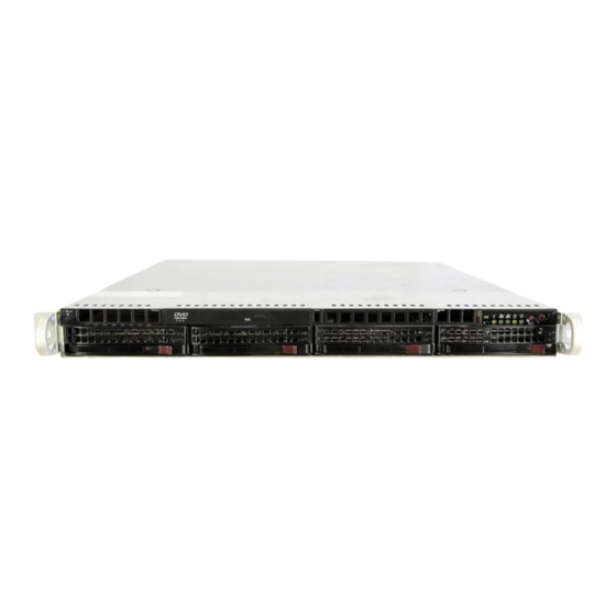
UPER ERVER 6016T-URF4+/6016T-NTRF4+ User's Manual Figure 6-1. Chassis: Front and Rear Views Slim DVD-ROM Control Panel SAS/SATA Drive Bays (4) Power Supplies IPMI LAN USB Ports PCI Expansion Slots (w/riser card) Mouse/Keyboard Ports COM1 Port VGA Port Control Panel The control panel (located on the front of the chassis) must be connected to the JF1 connector on the serverboard to provide you with system status indications. -
Page 65: System Fans
Chapter 6: Advanced Chassis Setup System Fans Five 4-cm heavy duty counter-rotating fans provide the cooling for the 6016T- URF4+/6016T-NTRF4+. Each fan unit is actually made up of two fans joined back- to-back, which rotate in opposite directions. This counter-rotating action generates exceptional airfl... -
Page 66: Accessing The Drive Bays
UPER ERVER 6016T-URF4+/6016T-NTRF4+ User's Manual Figure 6-2. System Cooling Fans Accessing the Drive Bays SATA Drives: Because of their hotswap capability, you do not need to access the inside of the chassis or power down the system to install or replace the SATA drives. Proceed to the next section for instructions. -
Page 67: Hard Drive Installation
Chapter 6: Advanced Chassis Setup Hard Drive Installation The hard drives are mounted in drive carriers to simplify their installation and removal from the chassis. System power may remain on when removing carriers with drives installed. These carriers also help promote proper airfl ow for the drive bays. -
Page 68: Hard Drive Backplane
UPER ERVER 6016T-URF4+/6016T-NTRF4+ User's Manual Installing/Removing a Hard Drive To remove a carrier, push the release button located beside the drive LEDs. Swing the colored handle fully out and use it to pull the unit straight out (see Figure 6-4). Note: Your operating system must have RAID support to enable the hot-plug ca- pability of the hard drives. -
Page 69: Dvd-Rom Drive Installation
Chapter 6: Advanced Chassis Setup DVD-ROM Drive Installation The top cover of the chassis must be opened to gain full access to the DVD-ROM drive bay. The 6016T-URF4+/6016T-NTRF4+ accomodates only slim-line DVD- ROM drives. Side mounting brackets are needed to mount a slim-line DVD-ROM drive in the 6016T-URF4+/6016T-NTRF4+ server. -
Page 70: Power Supply
UPER ERVER 6016T-URF4+/6016T-NTRF4+ User's Manual Power Supply The SuperServer 6016T-URF4+/6016T-NTRF4+ has a 700 watt redundant power supply consisting of two power modules. Each power supply module has an auto- switching capability, which enables it to automatically sense and operate at a 100V - 240V input voltage. - Page 71 Chapter 6: Advanced Chassis Setup Figure 6-5. Removing/Replacing the Power Supply...
- Page 72 UPER ERVER 6016T-URF4+/6016T-NTRF4+ User's Manual Notes 6-10...
-
Page 73: Chapter 7 Bios
Chapter 7: BIOS Chapter 7 BIOS Introduction This chapter describes the AMI BIOS Setup Utility for the X8DTU-LN4F+. The AMI ROM BIOS is stored in a Flash EEPROM and can be easily updated. This chapter describes the basic navigation of the AMI BIOS Setup Utility setup screens. Starting BIOS Setup Utility To enter the AMI BIOS Setup Utility screens, press the <Delete>... -
Page 74: Starting The Setup Utility
UPER ERVER 6016T-URF4+/6016T-NTRF4+ User's Manual Starting the Setup Utility Normally, the only visible Power-On Self-Test (POST) routine is the memory test. As the memory is being tested, press the <Delete> key to enter the main menu of the AMI BIOS Setup Utility. From the main menu, you can access the other setup screens. - Page 75 Chapter 7: BIOS System Overview: The following BIOS information will be displayed: System Time/System Date Use this option to change the system time and date. Highlight System Time or Sys- tem Date using the arrow keys. Key in new values through the keyboard and press <Enter>.
-
Page 76: Advanced Setup Confi Gurations
UPER ERVER 6016T-URF4+/6016T-NTRF4+ User's Manual Advanced Setup Confi gurations Use the arrow keys to select Boot Setup and hit <Enter> to access the submenu items: Boot Features Quick Boot If enabled, this feature will skip certain tests during POST to reduce the time needed for system boot. -
Page 77: Processor And Clock Options
Chapter 7: BIOS Hit 'Del' Message Display This feature displays "Press DEL to run Setup" during POST. The options are Enabled and Disabled. Interrupt 19 Capture Interrupt 19 is the software interrupt that handles the boot disk function. When this item is set to Enabled, the ROM BIOS of the host adaptors will "capture"... - Page 78 UPER ERVER 6016T-URF4+/6016T-NTRF4+ User's Manual Clock Spread Spectrum Select Enable to use the feature of Clock Spectrum, which will allow the BIOS to monitor and attempt to reduce the level of Electromagnetic Interference caused by the components whenever needed. The options are Disabled and Enabled. Hardware Prefetcher (Available when supported by the CPU) If set to Enabled, the hardware pre fetcher will pre fetch streams of data and instruc- tions from the main memory to the L2 cache in the forward or backward manner to...
- Page 79 Chapter 7: BIOS Simultaneous Multi-Threading (Available when supported by the CPU) Set to Enabled to use the Simultaneous Multi-Threading Technology, which will result in increased CPU performance. The options are Disabled and Enabled. Active Processor Cores Set to Enabled to use a processor's Second Core and beyond. (Please refer to Intel's web site for more information.) The options are All, 1 and 2.
-
Page 80: Advanced Chipset Control
UPER ERVER 6016T-URF4+/6016T-NTRF4+ User's Manual Advanced Chipset Control The items included in the Advanced Settings submenu are listed below: CPU Bridge Confi guration This feature allows the user to confi gure CPU Bridge settings. The items included in the submenu are listed below. •... - Page 81 Chapter 7: BIOS Memory Mode The options are Independent, Channel Mirror, and Lockstep. Independent - All DIMMs are available to the operating system. Channel Mirror - The motherboard maintains two identical copies of all data in memory for redundancy. Lockstep - The motherboard uses two areas of memory to run the same set of operations in parallel.
- Page 82 UPER ERVER 6016T-URF4+/6016T-NTRF4+ User's Manual Intel I/OAT The Intel I/OAT (I/O Acceleration Technology) signifi cantly reduces CPU overhead by leveraging CPU architectural improvements, freeing resources for more other tasks. The options are Disabled and Enabled. DCA Technology (Available when Intel I/OAT is enabled) Select Enabled to use Intel's DCA (Direct Cache Access) Technology to enhance data transfer effi...
- Page 83 Chapter 7: BIOS USB Functions This feature allows the user to decide the number of onboard USB ports to be en- abled. The Options are: Disabled, 2 USB ports, 4 USB ports, 6 USB ports, 8 Ports, 10 Ports and 12 USB ports. USB 2.0 Controller (Available when the item: USB Functions is disabled) This item indicates if the onboard USB 2.0 controller is activated.
- Page 84 UPER ERVER 6016T-URF4+/6016T-NTRF4+ User's Manual ICH AHCI Codebase (Available when the option-AHCI is selected.) Use this feature to select the AHCI Codebase for the ICH South Bridge. The options are BIOS Native Module and Intel AHCI ROM. SATA#2 Confi guration (Available when the option-IDE is selected.) Selecting Enhanced will set SATA#2 to native SATA mode.
- Page 85 Chapter 7: BIOS Select Auto to allow the AMI BIOS to automatically detect the PIO mode. Use this value if the IDE disk drive support cannot be determined. Select 0 to allow the AMI BIOS to use PIO mode 0. It has a data transfer rate of 3.3 MB/s.
- Page 86 UPER ERVER 6016T-URF4+/6016T-NTRF4+ User's Manual Select UDMA2 to allow the BIOS to use Ultra DMA mode 2. It has a data transfer rate of 33.3 MB/s. Select UDMA3 to allow the BIOS to use Ultra DMA mode 3. It has a data transfer rate of 44.4 MB/s.
- Page 87 Chapter 7: BIOS SXB1 PCI-E 2.0 x16/x8 Option ROM/SXB3 PCI-E 2.0 x8 Option ROM/SXB2 PCI-E 2.0 x8/x4 Option ROM/SXB2 PCI-E 2.0 x4 Option ROM Select Enabled to enable PCI-E slots indicated above. It can also enable Option ROMs specifi ed to boot computer using a network interface from these slots. The options are Enabled and Disabled.
-
Page 88: Hardware Health Monitor
UPER ERVER 6016T-URF4+/6016T-NTRF4+ User's Manual Serial Port Number This feature allows the user decide which serial port to be used for Console Redi- rection. The options are COM 1 and COM 2. Base Address, IRQ This item displays the based address and IRQ of the serial port specifi ed above. - Page 89 Chapter 7: BIOS CPU Overheat Alarm This option allows the user to select the CPU Overheat Alarm setting which de- termines when the CPU OH alarm will be activated to provide warning of possible CPU overheat. Warning! 1.Any temperature that exceeds the CPU threshold tempera- ture predefi...
- Page 90 UPER ERVER 6016T-URF4+/6016T-NTRF4+ User's Manual seeing a temperature reading (i.e., 25 C). The CPU Temperature feature will display the CPU temperature status as detected by the BIOS: Low – This level is considered as the ‘normal’ operating state. The CPU temperature is well below the CPU ‘Temperature Tolerance’.
- Page 91 Chapter 7: BIOS Select "Balanced/BL" for the onboard fans to run at a speed that will balance the needs between system cooling and power saving. The BL setting is recommended for regular systems with normal hardware confi gurations. Select "Energy Saving/ES" for best power effi...
-
Page 92: Trusted Computing
UPER ERVER 6016T-URF4+/6016T-NTRF4+ User's Manual NUMA Support Select Enabled to use the feature of Non-Uniform Memory Access to improve CPU performance. The options are Disabled, Enabled and NUMA for SLES 11. WHEA Support Select Enabled to enable Windows Hardware Error Architecture (WHEA) support which will provide a common infrastructure for the system to handle hardware errors on Windows platforms in order to reduce system crashes due to hardware errors and to enhance system recovery and health monitoring. - Page 93 Chapter 7: BIOS TPM Owner Status This item displays the status of TPM Ownership. IPMI Confi guration Intelligent Platform Management Interface (IPMI) is a set of common interfaces that IT administrators can use to monitor system health and to manage the system as a whole.
- Page 94 UPER ERVER 6016T-URF4+/6016T-NTRF4+ User's Manual • Event Data. Clear BMC System Event Log Clear BMC System Log now Select OK and press the <Enter> key to clear the BMC system log immediately. Select Cancel to keep the BMC System log. The options are OK and Cancel. Caution: Any cleared information is unrecoverable.
- Page 95 Chapter 7: BIOS Gateway Address (When IP Address Source is set to 'Static') The BIOS will automatically enter the Gateway address of this machine; however it may be overwritten. The value of each three-digit number separated by dots should not exceed 255. Mac Address (When IP Address Source is set to 'Static') The BIOS will automatically enter the Mac address of this machine;...
-
Page 96: Security Settings
UPER ERVER 6016T-URF4+/6016T-NTRF4+ User's Manual Security Settings The AMI BIOS provides a Supervisor and a User password. If you use both pass- words, the Supervisor password must be set fi rst. Supervisor Password This item indicates if a Supervisor password has been entered for the system. "Not Installed"... -
Page 97: Boot Confi Guration
Chapter 7: BIOS Clear User Password (Available only when User Password has been set) This item allows you to clear a user password after it has been entered. Password Check Select Setup for the system to check for a password at Setup. Select Always for the system to check for a password at bootup. -
Page 98: Exit Options
UPER ERVER 6016T-URF4+/6016T-NTRF4+ User's Manual • 1st Drive - [RAID: XXXXXXXXX] Retry Boot Devices Select Enabled to enable Retry Boot Devices support to allow the system to attempt to boot from a specifi c boot device after a boot failure. The options are Enabled and Disabled. - Page 99 Chapter 7: BIOS Load Optimal Defaults To set this feature, select Load Optimal Defaults from the Exit menu and press <Enter>. Then, select OK to allow the AMI BIOS to automatically load Optimal De- faults to the BIOS Settings. The Optimal settings are designed for maximum system performance, but may not work best for all computer applications.
- Page 100 UPER ERVER 6016T-URF4+/6016T-NTRF4+ User's Manual Notes 7-28...
-
Page 101: Appendix A Bios Error Beep Codes
Appendix A: BIOS Error Beep Codes Appendix A BIOS Error Beep Codes During the POST (Power-On Self-Test) routines, which are performed each time the system is powered on, errors may occur. Non-fatal errors are those which, in most cases, allow the system to continue the boot-up process. - Page 102 UPER ERVER 6016T-URF4+/6016T-NTRF4+ User's Manual Notes...
-
Page 103: Appendix B System Specifi Cations
Appendix B: System Specifi cations Appendix B System Specifi cations Processors Single or dual Intel® 5500/5600 Series processors in LGA1366 sockets Note: Please refer to our web site for a complete listing of supported processors. Chipset Intel 5520/ICH10R chipset BIOS 32 Mb AMI®... - Page 104 UPER ERVER 6016T-URF4+/6016T-NTRF4+ User's Manual Serverboard X8DTU-LN4F+ (Proprietary form factor) Dimensions: 14.85 x 12.68 in (377 x 322 mm) Chassis SC819TQ-R700U (1U rackmount) Dimensions: (WxHxD) 19 x 1.7 x 27.75 in. (483 x 43 x 705 mm) Weight Gross Weight: 38.5 lbs. (17.5 kg.) System Cooling Five 4-cm counter-rotating fans (FAN-0086L4) System Input Requirements...
- Page 105 Appendix B: System Specifi cations Regulatory Compliance Electromagnetic Emissions: FCC Class A, EN 55022 Class A, EN 61000-3-2/-3-3, CISPR 22 Class A Electromagnetic Immunity: EN 55024/CISPR 24, (EN 61000-4-2, EN 61000-4-3, EN 61000-4-4, EN 61000-4-5, EN 61000-4-6, EN 61000-4-8, EN 61000-4-11) Safety: CSA/EN/IEC/UL 60950-1 Compliant, UL or CSA Listed (USA and Canada), CE Marking (Europe) California Best Management Practices Regulations for Perchlorate Materials:...
- Page 106 UPER ERVER 6016T-URF4+/6016T-NTRF4+ User's Manual Notes (continued from front) The products sold by Supermicro are not intended for and will not be used in life support systems, medical equipment, nuclear facilities or systems, aircraft, aircraft devices, aircraft/emergency com- munication devices or other critical systems whose failure to perform be reasonably expected to result in signifi...
Need help?
Do you have a question about the SUPERSERVER 6016T-URF4+ and is the answer not in the manual?
Questions and answers