Table of Contents
Advertisement
ASSEMBLY INSTRUCTIONS
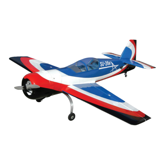
A High-Performance Aerobatic Model of the Sukhoi Su-26M
The full scale Sukhoi Su-26M was designed for one
thing: unsurpassed, spectacular aerobatic performance
in competition. Advanced Scale Models has designed
and built this very realistic scale model with that same
uncompromising spirit. The ASM Sukhoi Su-26M looks
great and flies superbly. Its unique color scheme presents
well in the air and draws attention everywhere it goes. Its
beautiful, fully-round fiberglass cowling matches the colors
of the fuselage for a professional appearance.
Assembly of this detailed ARF model is fast and easy
too. Its convenient-to-transport plug-in wings easily slide
together at the flying field. Each wing half has independent
servos with short 3mm pushrods for solid, secure aileron
control. A removable canopy with crutch allows easy
access to radio gear and more. This model is hassle-free.
You'll be in the air fast. We know you'll enjoy flying your
ASM Sukhoi Su-26M.
Wing Span: 7.8m (25.6ft)
Gross Weight (Empty): 670kg (1,477lb)
maximum Allowed Speed: 450km/h (280mph)
Made in China
ASm Sukhoi Su-26m SpEciFicATionS And FEATuRES
Wing Span: 1700mm (67 Inches)
l
Wing Area: 47.7dm
l
Length: 1470mm (58 Inches)
l
Weight RTF: 4.53kg (10 Pounds) Depending on Equipment Used
l
Wing Loading: 95g/dm
l
Functions: Elevator, Ailerons, Rudder and Throttle
l
Radio Required: 4 Channel or More with High-Torque Ball Bearing Servos
l
Engine Required: 1.20~1.60 2-Stroke / 1.50 ~2.10 4-Stroke / 26~35cc Gasoline
l
Plywood, Balsawood, Carbon Fibre Airframe with Highly-Detailed Moulded Skins
l
Factory-Covered Wing Panels, Painted Fuselage and Glass-Fibre Cowl
l
2-Piece Wing for Easy Transportation and Convenient Storage
l
Removable Canopy Crutch for Easy Access to Electronics
l
Exceptional Flying Qualities - Highly Aerobatic!
l
True-to-Scale Airframe with Full-Round Fuselage and Clear Moulded Canopy
l
Accepts Affordable Radios and a Wide Array of Engines
l
FuLL-ScALE Sukhoi Su-26m SpEciFicATionS
Wing Area: 11.83m
2
(127.3ft
2
l
maximum Takeoff Weight: 962kg (2,121lb)
l
Landing distance: 250m (820ft)
l
Page 1
2
(760 Square Inches)
2
(31 Ounces/Square Foot)
)
Length: 6.83m (22.4ft)
height: 2.4m (7.9ft)
l
l
Engines: 1 x M-14P 360hp Radial
l
Stall Speed: 110km/h (68mph)
l
Kit Product Number ASM007
Advertisement
Table of Contents

Subscribe to Our Youtube Channel
Related Manuals for advanced scale models Sukhoi SU-26M


Summary of Contents for advanced scale models Sukhoi SU-26M
- Page 1 ASSEMBLY INSTRUCTIONS A High-Performance Aerobatic Model of the Sukhoi Su-26M The full scale Sukhoi Su-26M was designed for one ASm Sukhoi Su-26m SpEciFicATionS And FEATuRES thing: unsurpassed, spectacular aerobatic performance Wing Span: 1700mm (67 Inches) in competition. Advanced Scale Models has designed Wing Area: 47.7dm...
-
Page 2: Safety Warnings
cuSTomER SERVicE inFoRmATion In the USA In the EU Global Services Ripmax Ltd. In Australia 18480 Bandilier Circle 241 Green Street Model Engines (Aust.) PTY. LTD. Fountain Valley, CA 92708 Enfield, EN3 7SJ, U.K. P.O. Box 828, Noble Park, Phone: (714) 963-0329 Phone: +44(0) 20 8282 7500 VIC., 3174 Fax: (714) 964-6236... - Page 3 kiT conTEnTS Before you begin assembly, group the parts as we list them below. This will ensure that you have all of the parts before you begin assembly and it will also help you become familiar with each part. If you find any parts missing or damaged, please contact your local distributor directly, using the customer Service information on the previous page.
-
Page 4: Tips From The Pros
AiLERon conTRoL SYSTEm ASSEmBLiES q (2) 70mm (2-3/4") Threaded Pushrods q (2) Nylon Control Horns with Backplates q (4) Clevises q (4) M2 x 25mm Machine Screws q (4) M3 Hex Nuts q (8) Nylon Hinge Points EnGinE mounT ASSEmBLY q (2) Adjustable Engine Mounting Beams q (4) M4 x 25mm Socket-Cap Screws q (4) M4 x 35mm Machine Screws... -
Page 5: Wing Panel Assembly
When gluing anything that has a smooth surface, it's important to lightly roughen the gluing surfaces with 220 grit sandpaper. This will allow the glue to stick better. Also, never glue directly to the covering material. Always remove the covering material from the gluing surfaces prior to gluing the parts together. -
Page 6: Step 3: Installing The Aileron Servos
q After the epoxy sets up, apply a thin layer of 5 minute epoxy to the exposed half of each hinge, then hinge the aileron to the wing panel, making sure to wipe away any excess epoxy before it cures. IMPORTANT Push the aileron firmly into place to ensure that the hinge gap is as tight as possible. - Page 7 q Tie the end of the length of string that's inside the servo mounting hole to the servo extension plug, then pull the string from the other end to guide the servo extension lead out through the root end of the wing panel. q Install the aileron servo into the mounting hole, making sure to drill (1.6mm) 1/16"...
-
Page 8: Wing Panel Installation
WinG pAnEL inSTALLATion STEp 1: inSTALLinG ThE WinG joinER TuBE q Slide one end of the wing joiner tube into one wing panel, making sure to line up the predrilled hole in the wing joiner tube with the predrilled hole in the bottom of the wing panel. - Page 9 q With the wing panels mounted to the fuselage, use a ruler to measure the distance between the tips of the stabiliser and the tips of the wing. Pivot the front of the stabiliser until both of these measurements are equal. When both of these measurements are equal, you're assured that the stabiliser is square to the wing.
- Page 10 IMPORTANT Because the stabiliser has to slide into place through the fuselage, apply epoxy only to the stabiliser. This will prevent the epoxy from spreading over the entire length of one half of the stabiliser when you slide it into place. q Apply a generous amount of 30 minute epoxy to onLY the top and bottom gluing surfaces of the stabiliser.
-
Page 11: Step 4: Installing The Main Gear Wheels
STEp 2: inSTALLinG ThE TAiL WhEEL BRAckET q Carefully cut off the excess portion of the tail wheel wire so that it's flush with the tail wheel tiller arm. IMPORTANT When installing the tail wheel bracket in the next procedure, make sure that the slot in the tiller arm is slipped over the end of the steering pin. -
Page 12: Elevator Control System Installation
q Slide one main gear wheel onto the axle, then secure the wheel into place, using one wheel collar and one grub screw. Tighten the grub screw firmly, then double-check that the wheel spins freely. q Repeat the previous procedures to installed the second threaded axle and main gear wheel. ELEVAToR conTRoL SYSTEm inSTALLATion STEp 1: inSTALLinG ThE ELEVAToR SERVoS q Plug one 600mm (24") servo extension onto each elevator servo lead. -
Page 13: Rudder Control System Installation
IMPORTANT The elevator servo mounting positions are set up so that the left-side servo arm points up and the right-side servo arm points down. This allows both pushrods to move the same direction without have to use a reversed servo or an electronic servo reverser. - Page 14 q After the C/A fully cures, thread one adjustable control horn onto each end of the threaded rod, making sure that both control horns are even with the outside edge of the threaded rod. STEp 3: inSTALLinG ThE RuddER puLL-puLL cABLES q Using a pair of wire cutters, carefully cut the stranded pull-pull cable exactly in half.
-
Page 15: Engine Installation
q Thread one 2mm hex nut onto each of the remaining two threaded couplers, then thread one clevis onto each threaded coupler and snap the clevises into the outermost holes in the servo arms. q Attach the pull-pull cables to the threaded couplers, making sure that the pull-pull cables are not crossed over each other and that they're running below the fuselage bulkhead cross-braces. -
Page 16: Throttle Control System Installation
q Mark the locations of the engine mounting holes onto the engine mounting beams, then drill 4.5mm (11/64") diameter holes through the engine mounting beams at the marks you drew. q Install your engine onto the engine mounting beams using four M4 x 35mm machine screws, four M4 flat washers, four M4 split washers and four M4 lock nuts. -
Page 17: Step 1: Assembling The Fuel Tank
q Connect your radio system and check that the throttle servo output shaft is rotating in the correct direction, then position the throttle control stick and the throttle trim lever to their lowest positions. q Slide the adjustable pushrod connector assembly onto the pushrod, then install the servo horn onto the servo, making sure that it's angled approximately 30 degrees from centre. -
Page 18: Cowl Installation
q Test-fit and glue the firewall support plate to the top of the engine mounting box, using a generous amount of epoxy. coWL inSTALLATion STEp 1: inSTALLinG ThE coWL mounTinG BRAckETS q Install the four cowl mounting brackets onto the firewall, making sure that the end of each mounting bracket is flush with the surface of the fuselage. -
Page 19: Final Assembly
q Remove the cowl and measure forward from each of the marks you drew to outline the back edge of the cowl to the centre of the cowl mounting block, then transfer each of these measurements onto the cowl to position the mounting holes. -
Page 20: Aircraft Setup Information
AiRcRAFT SETup inFoRmATion BALAncE poinT 100mm (4") BAck FRom ThE LEAdinG EdGE oF ThE WinG, mEASuREd AT ThE FuSELAGE SidES. q Turn the aircraft upside down, place your fingers on the wing at the balance point, and carefully lift the aircraft. If the nose of the aircraft drops, the aircraft is nose heavy. -
Page 21: Pre-Flight Check And Safety
conTRoL SuRFAcE LinkAGES If you don't maintain the proper mechanical advantage on the control surfaces, control surface flutter may result, which can cause your aircraft to lose control and crash. Mechanical advantage refers to the distance that the pushrod attachment points (pivot points) are from the servos and the control surfaces. - Page 22 AiRcRAFT TRim chART After you have test-flown and done the initial trim changes to the aircraft, use this trimming chart to begin trimming your aircraft. Following and adhering to this chart will result in the ability to diagnose trim problems and correct those problems using the simple adjustments shown below.
-
Page 23: Flying Tips
FLYinG TipS Takeoff generally requires no more than 50% power. The aircraft tracks straight and requires very little rudder correction during the takeoff roll using this power setting. Aileron response is very rapid and a little sensitive close to centre. Using an exponential setting of approximately 30% makes precision flying a lot easier. -
Page 24: Our Guarantee
In that Advanced Scale Models has no control over the final assembly or material used for final assembly, no liability shall be assumed for any damage resulting from the use by the user of the final user-assembled product. By the act of using the final user-assembled product, the user accepts all resulting liability.
Need help?
Do you have a question about the Sukhoi SU-26M and is the answer not in the manual?
Questions and answers