Table of Contents
Advertisement
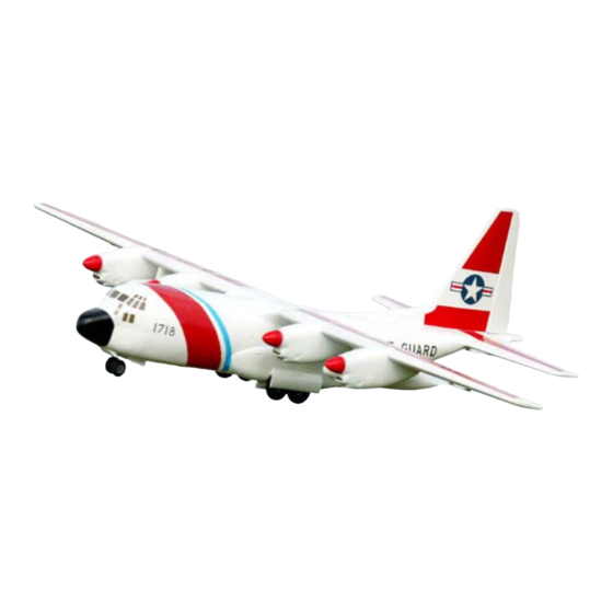
Semi scale model of the
world famous Military
Transport Aircraft
History of the C-130 Hercules
The versatile Lockheed C-130 Hercules was originally designed during the 1950s, as an assault
transport, but was adapted for a variety of missions, including: special operations (low level and
attack), close air support, mid-air space capsule recovery, search and rescue, aerial refuelling,
weather mapping and reconnaissance, electronic surveillance, fire fighting, aerial spraying and
natural disaster relief missions.
The first of two test aircraft made its maiden flight in August 1954. The C-130 has now accumulated
over 20 million flight hours and currently serves with over 60 countries. The C-130 is expected to
remain in production well into the 21st Century.
Wingspan: 39.7 metres (132 ft. 7")
Max. Take Off Weight: 155,000 lbs (69,750 kg)
INSTRUCTION MANUAL
Speed: 374 mph @ 6,060 metres (20,000 ft)
C-130
Hercules
Specifications
Wingspan:
2540mm (100")
Length:
1830mm (72")
Engines:
4 x brushless electric or 4 x
.25 - .32 two stroke or 4 x .26 -
.30 four stroke glow engines
Radio:
minimum 5 channels (6 with
optional retracts fitted)
-
Length: 29.3 metres (97 ft. 9")
-
Power Plants: 4 x 4,300 hp turboprops
-
Advertisement
Table of Contents

Related Manuals for advanced scale models C-130 Hercules


Summary of Contents for advanced scale models C-130 Hercules
-
Page 1: Instruction Manual
History of the C-130 Hercules The versatile Lockheed C-130 Hercules was originally designed during the 1950s, as an assault transport, but was adapted for a variety of missions, including: special operations (low level and attack), close air support, mid-air space capsule recovery, search and rescue, aerial refuelling, weather mapping and reconnaissance, electronic surveillance, fire fighting, aerial spraying and natural disaster relief missions. -
Page 2: Safety Warnings
Additional Items Required to Complete the Model: • 2 x 150mm (6”) Servo extension leads • 2 x 300mm (12”) Servo extension leads • 8 x 600mm (24”) Servo extension leads • Up to 7 ‘Y’ leads depending on radio system installed and glow or electric power •... - Page 3 Fuselage & Tail Step 1. Insert the alloy tube into a tail plane half and drill a 1.5mm (1/16”) pilot hole through the bottom of the tail plane and the alloy tube, 18mm inboard from the tail plane root rib. Step 2.
- Page 4 Step 6. The elevator control horns can now be installed. Carefully mark and drill pilot holes in the hard point. Be careful not to drill all the way through the elevator. Step 7. Locate the two elevator pushrods and fit one of the sup- plied clevises to each.
- Page 5 Step 13. Make sure that the grub screw on the rudder control arm lines up with the flat that is filed on the bottom of the torque rod. Step 14. Use a servo arm that is the same length as the rudder control arm.
- Page 6 Outer gear door Step 20. Inner gear door Secure the landing gear doors in place using a few drops of thin CA adhesive applied to each hinge leav- ing only a minimal gap between the fuselage and gear door. Inner gear door Regardless of whether fixed landing gear or the optional retracts are to be installed, the control horns and gear door wire should be installed.
-
Page 7: Motor Installation
Step 26. flap The flap control horn and servo is now installed the same way as described for the aileron servo, but with one exception. Because the flaps servos are required to move in the same direction when the flap control is used, one servo must be reversed or the pushrods should fitted to the same side of the servo arm on both flap servos. -
Page 8: Final Preparation
Step 30. Important! Please note that the four engine nacelles are numbered. Take care when fitting the nacelles to the wing and make sure that each nacelle is installed in the correct position. Step 31. Each nacelle is secured in place by a mounting bolt through the access holes in the top of the wing panels. -
Page 9: Flying Tips
Advanced Scale Models’ liability exceed the original cost of the kit. In that Advanced Scale Models has no control over the final assembly or the material used for final assembly, no liability shall be assuned for any damage resulting from the use by the user of the final user-assembled product. - Page 10 If you’ve followed these instructions carefully you should now have a beautiful model of the C-130 Hercules that is nearly ready to fly. Notice the word ‘nearly’! It’s now time to sit down and understand the final setup of the model ready for that first flight.
- Page 11 it more in an attempt to match RPMs exactly, remember ‘Golden Rule 1’. The likelihood is that one or more may need to be made richer when you do the nose up mixture test. When all is well, shut down all the engines and take a breather! Control Setup Make sure you have set the control movements according to the information given in these instructions.
- Page 12 This applies at all times and is done for a reason. Losing an engine at any time will result in a swing of some kind. The magnitude of the swing will depend on whether it is an inner or outer that is lost. The swing will be at its worst if it is an outer. If the inners are always at a high power setting when adjusting the outers that swing risk can be minimised.
- Page 13 Reduce the outers to about 40% on the ‘down wind leg and adjust the descent with the inners. Reduce the outers to about 25% on the ‘base leg’ and again adjust the decent with the inners. Once on ‘finals’ you can bring the outers back to idle and fly in on the inners alone.
- Page 14 Installing The Optional Air Retractable Landing Gear. Step 1. The main retractable landing gear units simply screw in place of the supplied fixed landing gear. Step 2. As mentioned earlier in the instructions, the lower Cut here. part of the front former will need to be cut away to allow the nose wheel to retract.
- Page 15 Step 6. The nose gear door assembly is made up of numerous components. Study the images carefully and fit the ‘L’ shaped hinges to the gear door as shown. Step 7. The nose gear door assembly is then attached to the bulkhead with the bracket positioned approximately 30mm 30mm down from the bottom of the fuselage.
- Page 16 Air Retract Plumbing Guide. ‘T’ piece Air supply line Air line ‘up’ Air line ‘down’ Page 16...
- Page 17 Page 17...
- Page 18 C-130 Addendum Step 1. Insert the alloy tube into a tail plane half and drill a 1.5mm (1/16”) pilot hole through the bottom of the tail plane and the alloy tube, 18mm inboard from the tail plane root rib. Step 3. Insert the alloy tube, with one tail plane half fitted, through the fuselage and fit the other half of the tail plane.
- Page 19 Page 18 Distributed in the USA by: Global Hobby 18480 Bandilier Circle, Fountain Valley, CA 92708. USA www.globalhobby.com Distributed in Europe by: Ripmax Ltd., 241 Green Street, Enfield, EN3 7SJ. UK www.ripmax.com Distributed in Australia by: Model Engines (Aust.) Pty. Ltd. P.O Box 828, Noble Park, VIC., 3174 www.modelengines.com.au...
Need help?
Do you have a question about the C-130 Hercules and is the answer not in the manual?
Questions and answers