Table of Contents
Advertisement
Quick Links
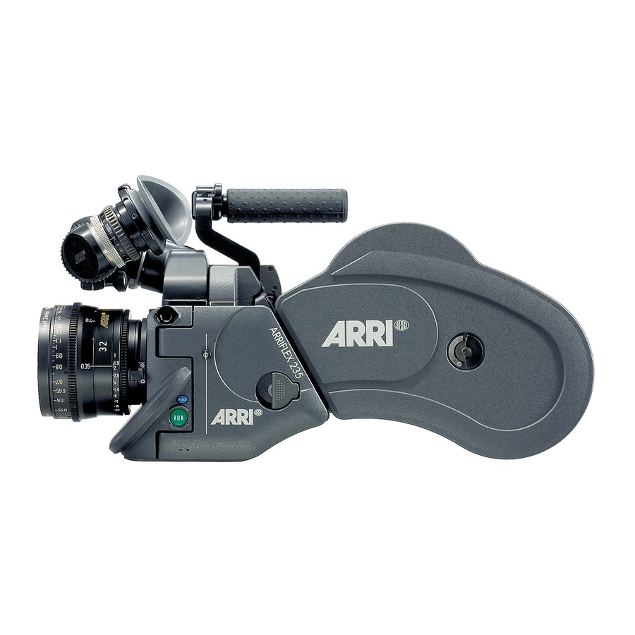
ARRIFLEX 235
Instruction Manual
As of: May 2005
A
,
.
LL ARTWORK
PICTURES AND TEXTS ARE COVERED BY OUR COPYRIGHT
T
(
.
.
CD-ROM,
-
)
.
HEY MUST NOT BE COPIED
E
G
ON
DISKS OR INTERNET
SITES
OR USED IN THEIR ENTIRE FORM OR IN EXCERPTS WITHOUT OUR PREVIOUS WRITTEN AGREEMENT
I
PDF-
,
.
F YOU ARE DOWNLOADING
FILES FROM OUR INTERNET HOMEPAGE FOR YOUR PERSONAL USE
MAKE SURE TO CHECK FOR UPDATED VERSIONS
W
,
.
E CANNOT TAKE ANY LIABILITY WHATSOEVER FOR DOWNLOADED FILES
AS TECHNICAL DATA ARE SUBJECT TO CHANGE WITHOUT NOTICE
Advertisement
Chapters
Table of Contents

Related Manuals for ARRI ARRIFLEX 235


Summary of Contents for ARRI ARRIFLEX 235
-
Page 1: Instruction Manual
ARRIFLEX 235 Instruction Manual As of: May 2005 LL ARTWORK PICTURES AND TEXTS ARE COVERED BY OUR COPYRIGHT CD-ROM, HEY MUST NOT BE COPIED DISKS OR INTERNET SITES OR USED IN THEIR ENTIRE FORM OR IN EXCERPTS WITHOUT OUR PREVIOUS WRITTEN AGREEMENT... - Page 2 adjustment knob for lock for telecoping manual image finder arm compensation locking key for manual image compensation finder arm ground glass adjustable mirror shutter PL-mount eyepiece lock eyepiece eyecup handgrip accessory mounting point RUN-button PHASE-button locking grip on camera door friction adjustment hook for focus tape for finder arm...
-
Page 3: Table Of Contents
Warning signs ... 7 General safety instructions ... 7 Specific safety instructions ... 9 2.2 Disclaimer ...10 3. General Description of the ARRIFLEX 235 ..13 4. Installation of the Camera ...15 4.1 Packing and Transport ...15 4.2 Tripod Heads ...15 4.3 Riser Plate ...16... - Page 4 8. Optics ...47 8.1 Lenses ...47 8.2 Viewfinder System ...48 The Eyepiece ... 48 Adjusting the Viewfinder ... 49 Image Compensation ... 50 9. Camera Operation ...53 9.1 Main Camera Switch ...53 9.2 Running and Stopping the Camera ...53 Running the Camera ... 53 Stopping the Camera ...
- Page 5 Cleaning the Throat Assembly ... 152 Setting Friction on the Shoulder Magazine ... 152 14. Appendix ...155 Loose Film Loops in the Magazine ... 155 Fuses ... 155 15. Technical Data ...161 16. Order Numbers ...163 17. ARRI Service ...165 18. Index ...167...
-
Page 7: Safety Instructions And Legal Disclaimer
ARRI, as they may cause hazards and void the warranty. Do not repair any part of the system. Repairs must only be carried out by authorized ARRI repair shops. Do not remove any safety measure of the system. - Page 8 Do not operate the system in high humidity areas or expose it to water or moisture. Do not place the system on an unstable cart, stand, tripod, bracket, or table. The system may fall, causing serious personal injury and damage to the system or other objects. Operate the system using only the type of power source indicated in the manual.
-
Page 9: Specific Safety Instructions
As the end-stops of the iris ring on the ARRIMACROS change when the lens is focussed, the ARRIMACROS may not be used with the ARRI Wireless Remote System (WRS) or the Lens Control System (LCS). Danger of injury with rotating drive gears on... -
Page 10: Disclaimer
For actual design-in, refer to the latest publications of ARRI data sheets or data books, etc., for the most up-to-date specifications. Not all products and/or types are available in every country. Please check with an ARRI sales representative for availability and additional information. - Page 11 In the case one or all of the forgoing clauses are not allowed by applicable law, the fullest extent permissible clauses by applicable law are validated. ARRI is a registered trademark of Arnold & Richter Cine Technik GmbH & Co Betriebs KG. Note: This product and the accessories recommended by the manufacturer fulfill the specifications of the EU-Guideline...
-
Page 13: General Description Of The Arriflex
• The mechanically adjustable mirror shutter on the ARRIFLEX 235 can be set to 45°, 60°, 75°, 90°, 105°, 120°, 135°, 144°, 150°, 172,8° and 180°. • The viewfinder can be rotated in two axes and can be used on both sides of the camera with full image compensation. - Page 14 magazine opening cover movement in locked position loop protector...
-
Page 15: Installation Of The Camera
When transporting the camera, pay attention that the movement is in the locked position photo. ➪ If the ARRIFLEX 235 is transported or stored without a magazine, the magazine opening ➪ photo cover should be attached. -
Page 16: Riser Plate
4.3 Riser Plate To use the ARRIFLEX 235 together with a bridge plate on a tripod, it is necessary to bring the camera into the correct position to the support rods. To do this, a riser plate is mounted to the bottom of the camera onto which the bridgeplate can be mounted. -
Page 17: Attaching The Bridge Plate To The Camera
Note: The upper plate of the bridge plate can be con- verted for use with Super 35. This ensures that the accessories are also exactly adapted to the displaced optical center of the Super 35 format. See also Chapter 12, Super 35. Attaching the Bridge Plate to the Camera •... -
Page 18: Removing The Camera From The Tripod
sliding upper plate clamping lever Removing the Camera from the Tripod • Before removing the camera make sure that all cables are disconnected and that the eyepiece leveling rod is detached. stop pin • For fast removal of the camera from the tripod, loosen the clamping lever photo, push in the stop pin ➪... -
Page 19: Lens Support
4.5 Lens Support The lens support consists of the lens support LS-7 (can be snapped onto 19 mm support rods) ➪ photo support LS-8 (can be pushed onto 15 mm support rods) and ➪ photo the respective lens support ring •... -
Page 20: Grip System
4.6 Grip System additional The multipurpose grip system on the ARRIFLEX 235 3/8“ mounting point guarantees high stability through its fixed connection to the camera body and provides numerous possibilities for attaching accessories. 3/8“ inner threads allow attachment in various positions. -
Page 21: Low Mode Handle
Low Mode Handle The low mode handle is a triple post handle. It can be mounted to the camera using 3 hexagonal screws To the low mode handle various accessories can be attached using the 3/8” holes. The low mode handle can be extended with the handle extension block photo. -
Page 22: Low Mode Support Lms-1
hexagonal screws Low Mode Support LMS-1 low mode support handle The Low Mode Support LMS-1 post camera handle with integrated Steadicam low mode low mode riser plate that attaches to the 235 camera body. It consists of low mode bracket the Low Mode Bracket (K4.65142.0) Support Handle (K4.65140.0) Riser (K4.65141.0) -
Page 23: Side Bracket Sbr-1
With the Low-Mode Riser, plate-to-lens distance is increased, but the plate level is now above the level of the viewfinder; a longer plate attached to the Riser will not collide with the viewfinder. This is especially useful in situations where rapid switching between operation in low-mode and operation with viewfinder is necessary. -
Page 24: Operation From The Shoulder
velcro tape ® shoulder pad RS-socket 4.7 Operation from the Shoulder The shoulder cushion can be used with or without the riser plate. • Attach the shoulder pad to the camera body by aligning the velcro tapes ® • Position the handgrip on the rosette and fasten with the fastening screw photo. -
Page 25: Power Supply
• Connect the camera to the mains unit or to the battery. • Switch on the main switch of the camera. Do not open the batteries! Charge batteries only with the proper ARRI chargers! Do not bypass the fuse or temperature switch! Do not heat NC-batteries! Do not short-circuit NC-batteries! photo. -
Page 26: Battery Nc 24/7 R
5.1 Battery NC 24/7 R The battery NC 24/7 R has a capacity of 7 ampere-hours. • Ensure that the main switch on the camera is off. • Plug the battery cable KC 20S or the spiral battery cable KC 29S into the power supply socket on the camera and into the battery-socket. -
Page 27: Mains Unit Ng 12/24 R
• Plug the battery cable KC 20S or the spiral battery cable KC 29S into the power supply socket on the camera and into the 26 V-socket on the mains unit. Note: The NG 12/24 R can easily be upgraded to an NG 12/26 R at an ARRI service center. -
Page 28: Accessory Power Supply
RS-sockets 5.5 Accessory Power Supply 24 V Accessories The RS-sockets supply the same voltage as the camera power supply. Ensure that the accessories to be used are suited to the available voltage! 24 V accessories are normally attached to the RS-sockets photo. -
Page 29: Magazines
ARRIFLEX 35 III and 35 II magazines – with the exception of the shoulder magazine and all 300m/1000ft magazines – can be used. Magazine Forward/Reverse operation ARRIFLEX 235 Shoulder Magazine 60/200 SHM-1 ... only forwards Shoulder Magazine 120/400 SHM-2 ... only forwards Steadicam Magazine 120/400 STM-1 ...forw./rev. ARRIFLEX 435 ARRIMAG 120 ...forw./rev. -
Page 30: Loading The Shoulder Magazine
film changing bag. Cutting the film through the middle of the perforation holes simplifies the loading process considerably. The ARRI Film Cutting Gauge ➪ photo the darkroom. film cutting gauge The following steps should be carried out in a darkroom or film changing bag! - Page 31 • Swing the roller arm ➪ photo away from the winding shaft until it locks in place. • Place the film roll next to the magazine, preferably on a film can. • Insert the film through the upper slit on the magazine throat assembly from the inside ➪...
- Page 32 • By again turning the drive gear counter-clockwise, trans- port the film inside the magazine. • Flip up the hinged locking clip on the take-up shaft photo. ➪ • Place an empty film core on the take-up shaft. Ensure that the take-up shaft catch engages the slot on the plastic core.
- Page 33 Note: To tension the film in the magazine, press in both tensioning plates ➪ photo wards. latches and turn out- tensioning plates...
-
Page 34: Removing Exposed Film
6.2 Removing Exposed Film roller arm The following steps should be carried out in a darkroom or a changing bag! • Check if the entire film has been wound into the interior of the magazine. If not, transport the film into the magazine by turning the drive gear counter-clockwise. -
Page 35: Transport And Storage
➪ photo avoid damage to the film stock and the magazine throat assembly. If the ARRIFLEX 235 is transported without a magazine it is recommended to attach the magazine opening cover photo. ➪ attached to... -
Page 37: Camera Body
7. Camera Body 7.1 Mechanically Adjustable Mirror Shutter The mirror shutter on the ARRIFLEX 235 can be mechanically adjusted while the camera is switched off. The shutter angle can be adjusted from 45° to 180°. The shutter locks in the following positions: 45°, 60°, 75°, 90°, 105°, 120°,... -
Page 38: Shutter Angle Measurement
• Insert the shutter tool unlock the shutter blade and to hold the shutter in ist shutter tool position. • Turn the movement inching knob to set the shutter to the desired shutter opening. Make sure the shutter registers properly at the set opening. •... -
Page 39: Filming With Hmi Light
Filming with HMI Light When lighting scenes with HMI/CID-discharge lamps, the pulsing light intensity is dependent on the supply frequency. To achieve constant exposure, the camera’s frame rate, the supply frequency of the lighting and the angle of the mirror shutter must all relate to each other. As the camera frame rate and the supply frequency of the lighting are normally given, compensation must be carried out through the angle of the mirror shutter. -
Page 40: Exchanging The Ground Glass
ground glass 7.2 Exchanging the Ground Glass • By briefly depressing the “PHASE”-button in standby, the shutter is positioned to protect the mirror surface from damage as far as possible • Before exchanging the ground glass, switch the tongue camera’s main switch off and disconnect the camera from the power supply! •... -
Page 41: Movement
7.3 Movement The ARRIFLEX 235 features a 5-link movement, equipped with ball-bearings for low maintenance. Never operate the movement locking mechanism while the camera is running! Removing the Spacer Plate • Open the movement by turning the inching knob ➪ photo... -
Page 42: Attaching The Magazine,Threading The Film
7.4 Attaching the Magazine, Threading the Film • Pull the magazine release lever remove the cover. • Open the camera door. • Remove the loop protector from the magazine. When attaching the magazine, pay attention that the film does not get caught between the magazine and the dovetail on the camera opening! magazine opening cover... - Page 43 Note: The magazine drive gear engages automatically. In case it does not engage properly, turn the magazine drive gear slightly and try again. • Check that the magazine is firmly seated. • Open the movement by turning the inching knob until the mark aligns with the mark on the movement and then turn the movement locking lever towards the “OPEN“...
- Page 44 Note: Before the movement block is swung forwards, make sure that the film is correctly positioned in relation to the film gate over the entire area, otherwise the film may be damaged! • Turn the movement locking lever counter-clockwise as far as it will go.
-
Page 45: Removing The Magazine
7.5 Removing the Magazine If the film has not run through the camera completely: • Open the camera door. • Open the movement by turning the inching knob ➪ photo until the mark aligns with the mark on the movement and then turn the movement locking lever ➪... -
Page 47: Optics
8. Optics 8.1 Lenses All ARRIFLEX lenses with a PL-mount can be used. Lenses with a Ø 41 mm standard or bayonet mount cannot be used. Heavy and long lenses, such as zoom-lenses, must be supported at all times. Attaching Lenses •... -
Page 48: Viewfinder System
8.2 Viewfinder System The viewfinder system on the ARRIFLEX 235 can be swivelled in two axes. The viewfinder image is always upright and correct left-to-right when the viewfinder is swivelled within the main axes An 80/20 beamsplitter for the video assist is integrated into the camera body. -
Page 49: Adjusting The Viewfinder
Adjusting the Diopter The diopter compensation is fitted with a scale of 1 to 12. Position “6” is normal focus. • To adjust, turn the ring right/left until the ground glass markings are totally in focus. Adjusting the Viewfinder Turning the Eyepiece The eyepiece can be rotated 360°... -
Page 50: Image Compensation
Note: The unlocking key can be locked in ist open position by turning it. Extending the Viewfinder Arm The viewfinder arm can be telescoped continuously by approx. 40 mm. • Turn the knurled ring viewfinder arm position. • Pull the viewfinder arm knurled ring •... - Page 51 Reactivating Image Compensation • Turn the adjustment knob ➪ photo position. Do not depress the locking key. Note: The automatic image compensation locks in two positions, 180° apart. This allows the image compensation to be set to provide an upright image when using a finder extension.
-
Page 53: Camera Operation
9. Camera Operation 9.1 Main Camera Switch • First switch on the mains unit (if used). • Connect the camera to the mains unit or to the battery. • Push the “ON/OFF” button ➪ photo camera on. Push the “ON/OFF” button for approx. 3 seconds to turn the camera off again. -
Page 54: Stopping The Camera
ON/OFF button RUN button operational control indicator • Briefly depress the “RUN”-button. While the camera is running up, the operation control indicator glows red. Once the set frame rate has been reached, the operation control indicator turns green. Stopping the Camera •... -
Page 55: Inching
Inching Inching can be started by depressing the “PHASE”-button while the camera is in standby. If the “PHASE”-button is only briefly depressed, the mirror shutter rotates half a revolution to enable an unrestricted view of the film gate (e.g. for checking the gate). If the “PHASE”-button is held depressed longer, the camera will inch forward at approx. -
Page 56: Overview Of Display Modes
Overview of Display Modes Mode 1 is displayed: after switching on the camera, after depressing the “RUN”-button or 30 seconds after the last operation. 1st Display Line Mode 1 total exposed film counter (m/ft) or take counter (m/ft) Mode 2 programmed frame rate (PS) ESU –... -
Page 57: Overview Of Display Symbols
Overview of Display Symbols Symbol Meaning glows The display is in Mode 1. glows Battery voltage too low glows Asynchronous operation (camera is not running at set frame rate) glows display shows current frame rate blinks ESU is connected and no sync-frequency is available 8 7 6.. -
Page 58: Film Counter
Mode 1 take length or total exposed film operational control indicator Film Counter Displaying the Film Counting Values (Modes 1 and 3) Film counting values are shown in Modes 1 and 3. Mode 3 Two different counting values are shown respectively: total exposed film or takelength •... -
Page 59: Displaying The Angle Of The Mirror Shutter (Mode 1)
Setting the Film Counter Configuration (Mode 3) The display configuration can be set individually. The two shown combinations are possible: The desired display configuration can be set in Mode 3: • Change from Mode 1 to Mode 3 by depressing the “MODE”-button twice. -
Page 60: Frame Rates
Frame Rates The ARRIFLEX 235 offers the possibility to set and store two frame rates. It is possible to select and store: • a standard frame rate (23.976, 24, 25, 29.97 and 30 fps), • and a freely programmed frame rate PS/CCU button in increments of 0.001 fps. - Page 61 Setting a Programmed Frame Rate (Mode 2) Standby Operation • Change from Mode 1 to Mode 2 by depressing the “MODE”-button once. • Depress the “SEL”-button repeatedly until the digit to be set blinks. • Depress the “SET”-button repeatedly until the desired value is reached.
-
Page 62: Shifting Phase
operational control indicator Fine-Tuning the Programmed Frame Rate (PS-Mode) Fine-tuning of the programmed frame rate can be carried out while the camera is running by means of the buttons “SEL” (slower) and “SET” (faster). The setting can be adjusted in increments of 0.001 fps. PS/CCU button •... -
Page 63: Displaying The Power Supply Voltage (Mode 3)
Displaying the Power Supply Voltage (Mode 3) • Change from Mode 1 to Mode 3 by depressing the “MODE”-button twice. The power supply voltage is shown in the lower line of the display. Setting the brightness of the button illumination •... -
Page 64: Switching On And Off The Warning Signal For Asynchronous Running (Mode 4)
Display Warning tone on start LS _ _ LS – _ LS _ – LS – – Switching On and Off the Warning Signal for Warning tone on stop Asynchronous Running (Mode 4) Standby Operation • Change from Mode 1 to Mode 4 by depressing the “MODE”-button three times. -
Page 65: Mode 5
Mode 5 Changing the Run up Speed: In menu 5 the run up speed can be changed in two steps. The faster run up speed uses less film, but sometimes when Steadicams or a very long power cable is used a longer run up time is easier on the batteries. - Page 66 flicker-free on/off switch check/hide menu on/off white balance gain control activate on screen program mode or store position outdoor/indoor of inserted window or store user text outdoor/manual É/Y È/C video with data mini-monitor clean video or Y-Signal connector or C-signal increase gain or cursor up or move inserted window up or increase blue...
-
Page 67: Video-Assist-System
10. Video-Assist-System 10.1 General Description of the IVS The Integrated Video-Assist System (IVS) for the ARRIFLEX 235 brings the highly praised video assist systems from the ARRIFLEX 435 and ARRICAM to the ARRIFLEX 235. It reassembles the IVS 435 control structure and of course... - Page 68 • Full white balance control In addition to the standard indoor white balance setting witch 3200 K, an outdoor setting with 5600 K and an automatic adjustment, red and blue channel can be fine tuned for manual white balance • Line Interpolation Even further resolution in camera run mode because of line interpolation, thus the image appears almost in field resolution.
- Page 69 • Dedicated controls Important image changes such as gain or white balance can be done immediately in parallel to the on-screen programming with dedicated key. • Image compare function It is possible to store a particular image and compare it against other images.
-
Page 70: Setup
screws for handle screws for transport cover 10.2 Setup 10.2.1 Installation A 1.5 mm allen key and a 3 mm allen key are used. Take the handle and the transport cover off the camera. handle • To take the handle off, open the two screws on the base of the handle ➪... - Page 71 • Pull off the plastic cover over the contacts. • Attach the video assist onto the ARRIFLEX 235 by moving it in the marked direction. The wedge on the IVS should mate with the matching dovetail on the photo.
-
Page 72: Cabling
handle • Push the IVS as shown until the gap between the camera and the IVS closes. • Close the screws on the IVS 3 mm allen key. • Remount the handle the base of the handle with a 3 mm allen key. 10.2.2 Cabling screws for IVS Outputs... - Page 73 Composite Video Outputs Composite video is only available if the output is switched to VBS out. • To switch to composite video (VBS mode), enter the main menu by pressing the Enter/Insert key Ñ for more than 3 seconds. Go to sub menu VIDEO/TEXT ADJUST.
- Page 74 MENU VIDEO/TEXT ADJUST - FLICKERFREE - LINE INTERP. -> - BNC OUT - Y/C DATA - MINI MON DATA - TXT WHITE LEV. - TXT INVERS - TXT FINE POS. - EXIT Y/C Output In comparison to the composite outputs, the Y/C outputs offer the even better S-VHS quality.
- Page 75 There are normal video and video with data signals available from the same pair of connectors. • To switch between normal video and video with data, use the on-screen program mode. Enter the main menu by pressing the Enter/Insert key Ñ for more than 3 seconds.
- Page 76 MENU VIDEO/TEXT ADJUST - FLICKERFREE - LINE INTERP. -> - BNC OUT - Y/C DATA - MINI MON DATA - TXT WHITE LEV. - TXT INVERS - TXT FINE POS. - EXIT Black and White Output The Y part of the Y/C output is a standard black and white signal.
- Page 77 • To switch between normal video and video with data, use the on-screen program mode. Enter the main menu by pressing the Enter/Insert key Ñ for more than 3 seconds. Go to sub menu VIDEO/TEXT ADJUST. The menu point Y/C DATA, which can only be reached if BNC OUT is on Y/C, switches between normal video and video with data on the Y/C signal.
- Page 78 MENU VIDEO/TEXT ADJUST - FLICKERFREE - LINE INTERP. - BNC OUT - Y/C DATA -> - MINI MON DATA - TXT WHITE LEV. - TXT INVERS - TXT FINE POS. - EXIT mini monitor connector Mini Monitor Output The IVS has a connector for a standard mini-monitor. As there is only one mini monitor connector, it is possible to switch between normal video and video with data on this output.
-
Page 79: Standard Video Controls
10.3 Standard Video Controls The IVS can be used like a standard video assist if no inserter features are used. Note: All currently used settings are stored even if the IVS or the camera is switched off. After restarting the IVS the settings are unchanged, except for the image stored mode, which will always come up in live mode. -
Page 80: Mechanical Iris
image rotation Hide Menu focus If the on-screen program mode is on because the settings are changed, the Menu (M) position clears the screen. For example, if color is to be changed with the on-screen program tool, the on-screen program window overlays the image. -
Page 81: Alignment Of The Image Position (X-, Y- And Rotation) And Focus
Check all settings on the connected monitor. If the mechanical iris is closed more than necessary, the IVS will compensate by increasing the gain and improve the image brightness electronically. This creates additional electronic noise. To avoid this, open the mechanical iris. •... -
Page 82: White Balance (Wb)
10.3.4 White Balance (WB) The IVS offers a choice for White Balance between • an automatic control (AWB) • fixed setting of indoor (IND) • fixed setting for outdoor (OTD) • and a full manual control of white balance (MAN). White balance can be adjusted in two different ways. - Page 83 Using the on-screen menu Please see chapter 10.4 Inserter Facilities for basics on the On-Screen display. In parallel to the control via keyboard, the white balance can also be programmed via the on-screen menu. • Enter the main menu by pressing the Enter/Insert key Ñ...
- Page 84 MENU WB/GAIN - WHITE BALANCE -> BLUE - MANUAL GAIN VALUE - EXIT Manual White Balance red increase/decrease Manual white balance red increase/decrease is only available if white balance control is on manual. If manual white balance is on MAN, it is possible to adjust the red and blue saturation of the video image manually.
- Page 85 Manual White Balance blue increase/decrease Manual white balance blue increase/decrease is only available if white balance control is on manual. If manual white balance is on MAN, it is possible to adjust the red and blue saturation of the video image manually. •...
-
Page 86: Gain Control
10.3.5 Gain Control The IVS can change the brightness of the video image electronically. This gain control can be automatic or manual. If the automatic control is selected, the IVS outputs the best possible image brightness at all the time. Light changes in front of the film camera are compensated by the IVS;... - Page 87 Using the on-screen menu Please see chapter 10.4 Inserter Facilities for basics on the On-Screen display. In parallel to the control via keyboard, the manual gain control can also be programmed via the on-screen menu. Manual gain control can be switched on or off. If it is on, specific values can be set between 0 (low gain) and 63 (high gain).
- Page 88 MENU WB/GAIN - WHITE BALANCE BLUE MANUAL GAIN -> VALUE - EXIT Manual Gain increase/decrease Manual gain increase/decrease is only available if manual gain control is on. • Move the cursor > with the keys Ê and Ë to the line –...
-
Page 89: Flicker Free On/Off
10.3.6 Flicker free on/off Flicker free can be switched off to bypass the digital frame store and have the video assist output with no delay. The film camera runs normally at a different speed than the video assist. E.g. the film camera runs at 24 fps and the video assist at 25 fps for PAL or 30 fps for NTSC. - Page 90 MENU VIDEO/TEXT ADJUST -> - FLICKERFREE - LINE INTERP. - BNC OUT Y/C DATA - MINI MON DATA - TXT WHITE LEV. - TXT INVERS - TXT FINE POS. - EXIT Using the on-screen menu Please see chapter 10.4 Inserter Facilities for basics on the On-Screen display.
-
Page 91: Changing Format Marking Number
10.3.7 Changing Format marking number The IVS can insert different format markings. It is possible to have • no format marking (OFF), • format marking number one (1), • format marking number two (2) • or both format markings at the same time (1 & 2) on display. Using the Keyboard The adjustment of the different format markings can only be done via the on-screen display as... - Page 92 MENU FORMAT MARKING -> - FORMAT POSITION 1 Ö POSITION 1 Ü POSITION 2 Ö POSITION 2 Ü WHITE LEVEL OUTSIDE - EXIT Using the on-screen menu Please see chapter 10.4 Inserter Facilities for basics on the On-Screen display. In parallel to the control via keyboard, the format marking number can also be programmed via the on-screen menu.
-
Page 93: Storing A Video Image
10.3.8 Storing a video image The IVS can store one particular image, display that or overlay it against the live image in front of the camera to compare both images. Although the functions to display a stored image and to compare a stored image against a live image are only available in the on-screen program mode, it is possible to store an image any time using the Enter/Insert key Ñ. - Page 94 MENU COMPARE/STORE - VIEW MODE -> - STORE IMAGE - CLEAR IMAGE - EXIT Using the on-screen menu Please see chapter 10.4 Inserter Facilities for basics on LIVE the On-Screen display. • Enter the main menu by pressing the Enter/Insert key Ñ...
-
Page 95: Inserter Facilities
10.4 Inserter Facilities In addition to the usual video assist functions, the IVS offers a variety of inserter facilities. There are two different groups of information: • Format markings Format markings, which are inserted electronically, are often more visible than format markings on the ground glass. - Page 96 • Within sub menus the cursor > can be moved up and down again by pressing the key Ê or Ë. The keys Í or Ì will now change settings (e. g. switch the insertion of a user text window on and off), or activates functions (position mode of a window or EXIT).
-
Page 97: Main Menu
10.4.2 Main Menu The inserter’s main menu is displayed on the monitor screen when the on-screen programming is activated by ➪ photo pressing the Enter/Insert key Ñ three seconds. An illuminated LED indicates that the on- screen programming is activated. Note: Pressing the Enter/Insert key Ñ... -
Page 98: Load/Store Menu
MENU LOAD/STORE -> - LOAD SET - STORE SET (CONFIRM BY ENTER) - SET ALL SETTINGS TO DEFAULT - EXIT 10.4.3 Load/Store Menu The IVS can store up to 6 sets of settings and recall them. Thus it is possible to make all settings for e.g. indoor shooting and store them as setting 1. - Page 99 Load Settings It is possible to load one out of six settings. Those new settings will influence all adjustments that can be made electronically. The new settings will immediately replace the previous settings. If the old settings might be needed, store them first as described in the next chapter Store Settings.
- Page 100 MENU LOAD/STORE - LOAD SET - STORE SET (CONFIRM BY ENTER) -> - SET ALL SETTINGS TO DEFAULT - EXIT ARE YOU SURE? (NO UNDO) -> - NO - YES - EXIT All Standard After the function set all settings to default was called, all settings are cleared.
- Page 101 The default values are: WB = INDOOR Manual Gain with GAIN = 0 Flicker free = ON Line Interpolation = ON Y/C data = ON BNC OUT = VBS Mini-Monitor Data = ON Format 1 = ON Format 2 = OFF WHITE LEVEL frame lines = 2 OUTSIDE AREA = DARK VIEW MODE = Live (Frame store is cleared)
-
Page 102: White Balance (Wb) And Manual Gain Control (Mgc) Menu
MENU WB/GAIN -> - WHITE BALANCE BLUE - MANUAL GAIN VALUE - EXIT MENU WB/GAIN -> - WHITE BALANCE BLUE - MANUAL GAIN VALUE - EXIT 10.4.4 White Balance (WB) and Manual Gain Control (MGC) Menu White balance and manual gain control allows to change the color appearance and brightness of the video image. - Page 103 • If white balance is on manual, the display will change. Lines left of RED and BLUE will appear indicating that the red and green saturation of the video image can now be changed. Manual White Balance red increase/decrease Manual white balance red increase/decrease is only available if white balance control is on manual.
- Page 104 MENU WB/GAIN - WHITE BALANCE -> BLUE - MANUAL GAIN VALUE - EXIT Manual White Balance blue increase/decrease Manual white balance blue increase/decrease is only available if white balance control is on manual. If manual white balance is on MAN, it is possible to adjust the red and blue saturation of the video image manually.
- Page 105 Manual Gain Control On/OFF In parallel to the control via keyboard, the manual gain control can also be programmed via the on-screen menu. Manual gain control can be switched on or off. If it is on, specific values can be set between 0 (low gain) and 63 (high gain).
- Page 106 MENU WB/GAIN - WHITE BALANCE BLUE - MANUAL GAIN -> VALUE - EXIT Manual Gain increase/decrease Manual gain increase/decrease is only available if manual gain control is on. If manual gain is on, it is possible to adjust the gain manually. •...
- Page 107 Exit Use exit to return to the main menu. • Move the cursor > with the keys Ê and Ë to the line – EXIT and press the key Í or Ì. Note: Pressing the Enter/Insert key Ñ for more than three seconds will cause the system to exit the on-screen programming mode completely, regardless of which menu is activated, with the...
-
Page 108: Video And Text Adjustment Menu
MENU VIDEO/TEXT ADJUST -> - FLICKERFREE - LINE INTERP. - BNC OUT Y/C DATA - MINI MON DATA - TXT WHITE LEV. - TXT INVERS - TXT FINE POS - EXIT 10.4.5 Video and Text Adjustment Menu This sub menu allows to change basic video settings as well as the appearance of the inserted man readable text. - Page 109 In parallel to the control via keyboard, the flicker free off can also be programmed via the on-screen menu. • Move the cursor > with the keys Ê and Ë to the line – FLICKERFREE. Pressing the key Í or Ì will switch flicker free mode off and on.
- Page 110 MENU VIDEO/TEXT ADJUST - FLICKERFREE - LINE INTERP. -> - BNC OUT Y/C DATA - MINI MON DATA - TXT WHITE LEV. - TXT INVERS - TXT FINE POS - EXIT MENU VIDEO/TEXT ADJUST - FLICKERFREE - LINE INTERP. - BNC OUT ->...
- Page 111 Mini-Monitor Output as normal video or video with data The mini monitor output can be programmed to have normal video or video with data. If the on-screen menu control is on (red LED next to the Enter/Insert key Ñ is on), there will always be data in this output.
- Page 112 MENU VIDEO/TEXT ADJUST - FLICKERFREE - LINE INTERP. - BNC OUT - Y/C DATA - MINI MON DATA - TXT WHITE LEV. -> - TXT INVERS - TXT FINE POS - EXIT MENU VIDEO/TEXT ADJUST - FLICKERFREE - LINE INTERP. - BNC OUT - Y/C DATA - MINI MON DATA...
- Page 113 Exit Use exit to return to the main menu. • Move the cursor > with the keys Ê and Ë to the line –EXIT and press the key Í or Ì. Note: Pressing the Enter/Insert key Ñ for more than three seconds will cause the system to exit the on-screen programming mode completely, regardless of which menu is activated, with the...
-
Page 114: Format Marking Menu
MENU FORMAT MARKING -> - FORMAT POSITION 1 Ö POSITION 1 Ü POSITION 2 Ö POSITION 2 Ü WHITE LEVEL OUTSIDE - EXIT 10.4.6 Format Marking Menu The IVS can insert two different format markings electronically in the video image, either individually or simultaneously. The position of these format markings can be set anywhere on the screen, to line up exactly with the ground glass markings. - Page 115 Activate Format Markings If the electronic format markings are not parallel to the ground glass format markings, readjust the CCD chip with the alignment screw, as shown in chapter 10.3.3 Alignment of the image position (X-, Y- and Rotation) and focus Note: Only active frame lines can be positioned.
- Page 116 MENU FORMAT MARKING - FORMAT -> - POSITION 1 Ö - POSITION 1 Ü - POSITION 2 Ö - POSITION 2 Ü - WHITE LEVEL OUTSIDE - EXIT Position - Positioning of the Format Marks The format markings can be adapted to every different format. 1&2 The format markings on the ground glass serve as a reference.
- Page 117 White Level - Setting the Brightness of the Format Markings The brightness of the format markings can be set to black (0), dark gray (1), and light gray (2) or white (3). • Move the cursor > with the keys Ê and Ë to the line –...
- Page 118 MENU FORMAT MARKING - FORMAT - POSITION 1 Ö - POSITION 1 Ü POSITION 2 Ö POSITION 2 Ü - WHITE LEVEL - OUTSIDE -> - EXIT Exit Use exit to return to the main menu. • Move the cursor > with the keys Ê and Ë to the line –...
-
Page 119: Compare/Store Menu
10.4.7 Compare/Store Menu The IVS can store one particular image, display it or overlay it against the live image in front of the camera to compare both images. Changing them immediately activates all settings. Check all settings on the connected monitor. •... - Page 120 MENU COMPARE/STORE - VIEW MODE -> - STORE IMAGE - CLEAR IMAGE - EXIT MENU COMPARE/STORE - VIEW MODE - STORE IMAGE -> - CLEAR IMAGE - EXIT Store image The IVS can store one particular image, display that or overlay LIVE it against the live image in front of the camera to compare both images.
- Page 121 Exit Use exit to return to the main menu. • Move the cursor > with the keys Ê and Ë to the line – EXIT and press the key Í or Ì. Note: Pressing the Enter/Insert key Ñ for more than three seconds will cause the system to exit the on-screen programming mode completely, regardless of which menu is activated, with the...
-
Page 122: System And Status Menu
MOVEMENT OPEN 25.7V NRDY FWD 0.000/24.000 MENU SYSTEM/STATUS -> - SYSTEM LINE - STATUS LINE - POSITION - BACKGROUND - FILM COUNTER - EXIT 25.7V NRDY FWD 0.000/24.000 10.4.8 System and Status Menu 180.0 The IVS can insert the camera system and status into the video image. - Page 123 If the film counter is in the take mode, the data in meter, foot or seconds of the last take are displayed. In the mode footage, the added length of the film through the camera in meter or feet is displayed. During programming the inserted data are not fully updated (e.
- Page 124 MENU SYSTEM/STATUS -> - SYSTEM LINE - STATUS LINE POSITION BACKGROUND FILM COUNTER - EXIT System Line This sub menu line switches the insertion of camera system data on (ON) and off (OFF) independently of other inserted data. • Move the cursor > with the keys Ê and Ë to the line –...
- Page 125 Status Line This submenu line switches the insertion of camera status data on (ON) and off (OFF) independently of other inserted data. • Move the cursor > with the keys Ê and Ë to the line – STATUS LINE. The keys Í or Ì switch the insertion on and off.
- Page 126 MENU SYSTEM/STATUS - SYSTEM LINE - STATUS LINE -> - POSITION - BACKGROUND - FILM COUNTER - EXIT MENU SYSTEM/STATUS - SYSTEM LINE - STATUS LINE - POSITION -> - BACKGROUND - FILM COUNTER - EXIT Position The window can be positioned anywhere on the monitor screen.
- Page 127 Film Counter The film counter is slaved to the footage counter of the film camera. It always displays the values, which are in the camera. Therefore there is no set or reset of film counter data on the IVS. • Move the cursor > with the keys Ê and Ë to the line –...
-
Page 128: User Text Menu
MENU USER TEXT -> - USER TEXT LINE - EDIT TEXT - CLEAR TEXT - POSITION - SIZE - BACKGROUND - EXIT PROD. NAME UNIT A TAKE 35 10.4.9 User Text Menu The IVS can insert additional text into the video image, for example the production name or a scene number. - Page 129 • Enter the User Text submenu from the main menu. Changing them immediately activates all settings. Check all settings on the connected monitor. User Text Line This sub menu line switches the insertion of additional text on (ON) and off (OFF) independently of other inserted data. •...
- Page 130 MENU EDIT TEXT (...) >X (...) > (...) > MOVE THE CURSOR X <> CHANGE CHARACTER EXIT PRESS E MENU USER TEXT - USER TEXT LINE - EDIT TEXT -> - CLEAR TEXT - POSITION - SIZE - BACKGROUND - EXIT The menu EDIT TEXT is displayed on the screen: •...
- Page 131 Position The window can be positioned anywhere on the monitor screen. • Move the cursor > with the keys Ê and Ë to the line – POSITION. Activate the positioning mode with the keys Í or Ì. The following menu is displayed on the screen: ->...
- Page 132 MENU USER TEXT - USER TEXT LINE - EDIT TEXT - CLEAR TEXT - POSITION - SIZE -> - BACKGROUND - EXIT Background The background of the window can be set electronically to black in normal display mode or to white in inverse mode (BOXED) to improve the readability.
- Page 133 Exit Use exit to return to the main menu. • Move the cursor > with the keys Ê and Ë to the line – EXIT and press the key Í or Ì. Note: Pressing the Enter/Insert key Ñ for more than three seconds will cause the system to exit the on-screen programming mode completely, regardless of which menu is activated, with the...
-
Page 135: Accessories
11. Accessories Accessory Mounting Points On the camera body and on the electronic cover there are accessory mounting points. Various accessories can be mounted to them by using 3/8” screws. Check that the screws are not reaching more than 9mm into the camera body from the photo, otherwise the contact surface ➪... -
Page 136: Universal Viewfinder Uv-1
allen screws Universal Viewfinder UV-1 When using anamorphic lenses, the UV-1 allows desqueezed viewing of the ground glass image. This viewfinder arm can also be switched over to check the anamorphically switching knob squeezed image. • To switch over the viewfinder image, turn the switching knob photo. -
Page 137: Work Light Wl-3
Work Light WL-3 • Screw the dovetail-adapter to the handgrip. • Slide the work light into the dovetail-guide and clamp. • Connect the plug to the “RS”-socket. • By adjusting the flexible arm, bring the work light into the desired position. The work light can be turned on and off with the ring on the lamp head brightness of the work light can be adjusted with the mechanical aperture. -
Page 138: Remote Run Switch Rs-4
Remote Run Switch RS-4 • Attach the remote run switch with the spring clamp ➪ photo (e.g. to the pan handle). • Plug the RS-4 plug into the “RS”-socket. -
Page 139: External Synchronization Unit Esu-1
External Synchronization Unit ESU-1 The external synchronization unit ESU-1 used with the ARRIFLEX 235 as well as with the 435 models, 535, 535B and 16SR 3/Advanced. It allows synchronization of the camera to other equipment such as TV monitors. By... -
Page 140: Remote Control Unit Rcu-1
Remote Control Unit RCU-1 The RCU-1 ➪ photo is a practical remote control unit for all new-generation ARRIFLEX cameras. It can be used in all applications that call for an uncomplicated, quick, sturdy and yet still comprehensive remote control. Complete programs can easily be created to control changing of frame rate over a certain period of time. - Page 141 • The RCU cable is connected to the remote socket ➪ photo on the camera. For further information see the RCU-1 instruction manual. Note: The RCU-1 will always operate in the HI ramping speed. Operation in LO is not possible. CCU and RU are not supported and could cause malfunction when connected.
- Page 142 IRIS sliding switch WRC/CAM sliding switch READY-LED SEL button MODE button OPEN/PHASE button rotary switch handwheel WRC-1 with WMU-3 RELEASE button RUN-LED radio channel ON button RF-LED CAL-LED SET button CAL button RAMP button COMPENSATION READY-LED rotary switch BAT-LED RUN-LED RUN button WRC-1 with WMU-1...
-
Page 143: Wireless Remote Control Wrc-1
ARRIFLEX camera models: ARRIFLEX 16SR 3/Advanced, 16SR 3 HS/Advanced, 535, 535B, 435 Advanced, 435ES and the ARRIFLEX 235. On the ARRIFLEX 235 it enables the user to remotely control: • the camera speed, • the aperture of the lens (iris), providing compensation for constant exposure. -
Page 145: Super 35
12. Super 35 When delivered, the camera is set to Super 35. The Super 35 format offers a range of technical advantages compared to filming with anamorphic lenses: • a larger selection of available focal lengths, • smaller and lighter-weight lenses, •... -
Page 146: Converting The Bridge Plateto Super 35
index arrows Converting the Bridge Plate to Super 35 The current position, standard or Super 35, is displayed screws by two index arrows on the sliding upper plate. The bridge plate can be converted to Super 35 as follows: • Remove the two screws •... -
Page 147: Maintenance
13. Maintenance When maintaining and cleaning the camera and accessories, pay careful attention to the following notes and tips: • Always disconnect the camera from the power supply. • Clean the camera and accessories only on a clean and flat surface which is covered with foam material or a clean, lint-free cloth. -
Page 148: Camera
film gate handle Camera Cleaning the Film Gate locking lever Loose dust or dirt leads to a layer of emulsion forming on the film gate. This can cause scratches on the film and can also lead to a change in the film’s coefficient of friction. The film gate must be removed for cleaning. - Page 149 To clean the film gate • Remove the layer of emulsion from the film gate with a plastic rod (e.g. an ARRI film gate cleaner). Under no circumstances use hard or metal objects. • When cleaning, pay particular attention to the area opposite the film guides of the movement if film stock...
-
Page 150: Cleaning The Spacer Gate
• Push the spacer gate downwards until it locks audibly in place. • Close the movement again. ➪ with a plastic rod (e.g. an ARRI film gate cleaner). ➪ photo photo. -
Page 151: Cleaning The Field Lens
Cleaning the Field Lens • By briefly depressing the “PHASE”-button, the shutter is positioned to protect the mirror surface from damage as far as possible. • Before cleaning the field lens, switch the camera’s main switch off and disconnect the camera from the power supply! •... -
Page 152: Magazine
holder plate screws Magazine Cleaning the Throat Assembly The throat assembly cleaning. • Loosen the three screws guide rollers assembly cover • Remove the holder plate protector. • Pull out the throat assembly cover. running surfaces • Clean the film running surfaces ➪... - Page 153 • Hang the hook of the measurement device on the film core which is to be measured. • Attach the open magazine to the camera. Do not place your hand in the running magazine! • To set the take-up shaft, run the camera at 24 fps. The tension measurement device should be showing ring “5”.
-
Page 155: Appendix
film loops may be formed in the magazine. Before the camera is started again, the film in the magazine must be tensioned manually. Fuses The ARRIFLEX 235 is equipped with self-resetting automatic fuses. It is therefore not necessary to replace blown fuses. - Page 156 Error text in display trAnS oPEn bound F-len Error Hot Error CntL Updt Async inching low battery Error text in IVS movement open maximum takelength exceeded motor excess temperature Controller Error software update in progress camera speed is not the choosen speed camera is inching camera supply voltage too low, change battery Problem...
- Page 157 Problem Scratches on the emulsion side of the negative In the image area, over several frames In the image area, short and periodically recurring (above and below) Outside the image area Scratches on the glossy side of the negative In the image area Outside the image area Scratching in general Cause...
- Page 158 Problem Unsteady Image Vertical Horizontal Pressure exposures arround perforation holes Image Problems Blurred image Cause Heavy emulsion build-up in the film gate area, damaged film perforation, very poor gliding ability of the raw film stock, film stock with positive perforation, dimensions of raw stock not within tolerance Heavy emulsion build-up in the film gate area, film edge is not straight...
- Page 159 Problem Problems at extremely low temperatures Damage to the film The camera does not reach the selected frame rate Problems in extremely high temperatures Increased emulsion build-up Cause Greatly reduced tensile strength and increased brittleness of raw stock. In temperatures under - 15°C (5° F) especially, a change in the film´s friction properties ocurs.
-
Page 161: Technical Data
15. Technical Data Film Format 35mm (DIN 15501) Magazines 235 Shoulder Magazine 60/200 (SHM-1) ... forward only, up to 60 fps 235 Shoulder Magazine 120/400 (SHM-2) ... forward only, up to 60 fps 235 Steadicam Magazine 120/400 (STM-1) ... forward up to 60 fps reverse 25 fps All ARRIFLEX 35 III and 35 II 60m/200ft and 120m/400ft magazines with exception of the shoulder magazine;... - Page 162 Ground Glasses Interchangeable for various filming formats, same ground glasses as Arriflex 435 Operating Temperature Range -20°C to +50°C (-4°F to +122°F) Power Supply 24 V DC Acceptable voltage range: ... 20.6…35 V DC Function Monitoring Power supply voltage (BAT) Synchronous running (ASY) Weight ...approx.
-
Page 163: Order Numbers
16. Order Numbers ARRIFLEX 235 Body 4 perforation ... K1.55000.0 ARRIFLEX 235 Body 3 perforation ... K1.55000.3 ARRIFLEX 235 Spherical Viewfinder set ... K2.55009.0 ARRIFLEX 235 Universal Viewfinder set ... K2.55010.0 Installation of the Camera ARRIHEAD 2 ... K2.43670.0 ARRIHEAD 2 with Encoders ... K2.52090.0 Hydrohead Studio 80 II M ... - Page 164 Magazines 235 Shoulder Magazine 60/200 (SHM-1) ... K2.55001.0 235 Shoulder Magazine 120/400 (SHM-2) ... K2.55016.0 235 Steadicam Magazine 120/400 (STM-1) ... K2.55008.0 Tool set for adjusting magazine friction ... K2.26100.0 Adaptor for use of K2.26100.0 in the 60m Magazine ... K5.65443.0 Optical Accessories Lightweight Follow Focus Set for 19mm (LFF-1/19) ...
-
Page 165: Arri Service
(West Coast) 600 North Victory Blvd. Burbank, California 91502 phone: (818) 841 70 70 fax: (818) 848 40 28 E-mail: arriflex@arri.com GB ... ARRI (GB) Ltd. 2 Highbridge Oxford Road Uxbridge Middlesex, UB8 1LX phone: (0) 1895 457 000 fax: (0) 1895 457 001 E-mail: sales@arri-gb.com... -
Page 167: Index
18. Index accessories ... 135 24 V ... 28 external synchronization unit ESU-1 ... 139 heated eyecup HE-4 ... 137 remote control unit RCU-1 ... 140 remote run switch RS-4 ... 138 universal viewfinder UV-1 ... 136 work light WL-3 ... 137 accessory mounting points ... - Page 168 cable cabling the IVS ... 72 KC-42S ... 137 KC 20S ... 26, 27 KC 29S ... 26, 27 camera camera body ... 37 installation ... 15 main switch ... 53 operation ... 53 starting ... 53 stopping ... 54 changing bag ...
- Page 169 overview of display modes ... 56 shutter angle ... 59 take length ... 58 total amount of exposed film ... 58 display mode at IVS ... 119 dovetail-adapter ... 137 edit text ... 129 emulsion build-up film gate ... 148 spacer gate ...
- Page 170 forward operation ... 61 frame rate changing while camera is running ... 61 fine-tuning ... 62 freely programmed frame rate ... 61 setting and storing ... 60 shifting phase ... 62 standard frame rate ... 60 frame store and compare ... 119 friction eyepiece ...
- Page 171 installation ... 15 IVS ... 70 inverse ... 112 iris IVS ... 80 off ... 79 on ... 79 setup ... 70 length unit (meters/feet), changing ... 59 lenses ... 47 attaching ... 47 lens support LS-7 ... 19 lens support LS-8 ... 19 support ...
- Page 172 main features IVS ... 67 menu IVS ... 97 mains unit NG 12/24 R ... 27 mains unit NG 12/26 R ... 27 maintenance ... 147 MAN ... 82 manual gain control ... 86 gain control on/off ... 105 gain increase/decrease ... 106 white balance blue ...
- Page 173 packing and transport ... 15 peak load, current ... 28 PHASE-button ... 55, 59, 62 phase shifting ... 62 pickup ... 139 pilottone generator ... 139 PL-mount ... 161 power supply ... 25, 162 power supply for accessories ... 28 power supply voltage display ...
- Page 174 standard video controls ... 79 automatic gain control ... 86 changing format marking number ... 91 flicker free on/off ... 89 focus ... 81 gain control ... 86 iris ... 80 on/off and check/hide menu ... 79 storing a video image ... 93 white balance ...
- Page 175 universal viewfinder UV-1 ... 136 user text menu ... 128 background ... 132 clear text ... 130 edit text ... 129 exit ... 133 position ... 131 size ... 131 user text tine ... 129 UV-1 universal viewfinder ... 136 VBS ...
- Page 176 white balance ... 82, 102 AWB ... 82 changing blue ... 82, 85 changing green ... 82 changing red ... 82, 84 IND ... 82 MAN ... 82 OTD ... 82 white balance/gain menu ... 102 exit ... 107 manual gain control on/off ... 105 manual gain increase/decrease ...
- Page 177 IVS Quick Reference MAIN MENU MENU LOAD/STORE -> - LOAD/STORE -> - LOAD SET - WB/GAIN - VIDEO/TEXT ADJ - STORE SET - FORMAT MARKING (CONFIRM BY - COMPARE/STORE ENTER) - SYSTEM/STATUS - USER TEXT - SET ALL SETTINGS TO - EXIT DEFAULT - EXIT...
- Page 178 © ARRI 2005 JThieser@arri.de Ident-No. K5.65348.0 available languages: English ARNOLD & RICHTER CINE TECHNIK Türkenstr. 89 • D-80799 München Phone +49 – 089 – 38 09 – 0 • Fax +49 – 089 – 38 09 – 12 44...
Need help?
Do you have a question about the ARRIFLEX 235 and is the answer not in the manual?
Questions and answers