Table of Contents
Advertisement
Quick Links
ARRIFLEX 16SR 3
Instruction Manual
As of: December 1992
A
,
-
.
LL ARTWORK
PICTURES AND TEXTS ARE COVERED BY OUR COPY
RIGHT
T
(
.
.
CD-ROM
I
-
)
.
HEY MUST NOT BE COPIED FOR REPRODUCTION
E
G
ON
DISKS OR
NTERNET
SITES
OR USED IN THEIR ENTIRE FORM OR IN EXCERPTS WITHOUT OUR PREVIOUS WRITTEN AGREEMENT
I
PDF-
I
-
,
.
F YOU ARE DOWNLOADING
FILES FROM OUR
NTERNET HOME
PAGE FOR YOUR PERSONAL USE
MAKE SURE TO CHECK FOR UPDATED VERSIONS
W
,
.
E CANNOT TAKE ANY LIABILITY WHATSOEVER FOR DOWNLOADED FILES
AS TECHNICAL DATA ARE SUBJECT TO CHANGE WITHOUT NOTICE
Advertisement
Table of Contents

Related Manuals for ARRI ARRIFLEX 16SR3


Summary of Contents for ARRI ARRIFLEX 16SR3
-
Page 1: Instruction Manual
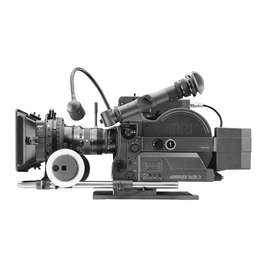
ARRIFLEX 16SR 3 Instruction Manual As of: December 1992 LL ARTWORK PICTURES AND TEXTS ARE COVERED BY OUR COPY RIGHT CD-ROM HEY MUST NOT BE COPIED FOR REPRODUCTION DISKS OR NTERNET SITES OR USED IN THEIR ENTIRE FORM OR IN EXCERPTS WITHOUT OUR PREVIOUS WRITTEN AGREEMENT PDF- F YOU ARE DOWNLOADING FILES FROM OUR... - Page 2 eyecup iris lever magazine safety latch ARRIGLOW film speed selector inching knob electronic inching/ phase button run LED display on/off push button push button SET push button SEL push button MODE slide switch carring handle on/off switch remote switch pitch adjustment main power receptacles 24V DC out friction adjustment...
-
Page 3: Safety Specifications
• Assembly and initial operation should only be carried out by qualified personnel already familiar with the equipment and the assembly procedures! • Use only original ARRI accessories and replacement parts! • Clean optic surfaces only with an optic brush or a clean optic cloth! In cases of solid dirt moisten an optic cloth with pure alcohol. -
Page 4: Table Of Contents
Attaching the magazine onto the camera ... 30 Removing the magazine ... 31 6. Optics Lenses ... 32 54mm PL-mount ... 34 41mm ARRI bayonet ... 35 Lens support ... 36 Viewfinder ... 38 Eyepiece ... 39 Eyecup ... 39 7. - Page 5 Finder extension FE-2 ... 46 Levelling rod for finder extension EL-3 ... 47 Heated eyecup HE-3 ... 48 8. Conversion from Normal 16 to Super 16 ... 49 Bridge plates BP-6 and BP-7 ... 53 Lightweight support ... 54 Video optic ... 54 9.
-
Page 7: The Arriflex 16Sr 3 - System-Camera
An addi- tional film gate is not necessary. • Due to the 54mm PL lens mount, all commonly avail- able lenses can be used. Lenses with a 41mm ARRI- bayonet-mount can be used with the single push- button release PL-mount-to-bayonet-mount adapter. - Page 8 status and functions of the camera. The ARRIFLEX 16SR 3 provides for on-board speed selection and speed changes while the camera is running up to 1/1000 of a frame accuracy,. without additional electronic accessoriesw. Instant on-the-fly-changes between preselected standard on-board and pro- grammed variable speeds are possible, as well as on- board phase shifting for filming of monitors.
-
Page 9: Installation
Tripod Heads The ARRIHEAD 2 with its compact construction is ideally suited to the ARRIFLEX 16SR 3. The hydro- heads ARRI 150 H, ARRI 150 M and ARRI 100 L can be used as well. Bridge Plate BP-6 The bridge plate allows quick mounting and balancing of the fully-equipped ARRIFLEX 16SR 3 system on the tripod. - Page 10 base plate springloaded stop pin adjustable top plate lock lever lock levers support rods...
-
Page 11: Bridge Plate Bp-7 With 15 Mm Support Rods
Mounting • Press in the spring-loaded stop pin upper sliding backplate off the base plate • Attach upper sliding plate with the central tie-down screw (3/8" thread) to the camera base, ensuring that the locating pins align with the holes in the camera base. - Page 12 remote switch receptables 24V DC out handgrip adjustment positions...
-
Page 13: Shoulder Set S-3
Shoulder Set S-3 The shoulder set S-3 has adjustable grips and an integrated shoulder pad which allows comfortable hand-held camera operation. Mounting • Attach the shoulder set with the central clamp screw into the tripod thread (3/8") on the camera base ensuring that the index pin on the shoulder set aligns correctly with the locating hole in the camera base. -
Page 15: Power Supply
3. Power Supply The camera is intended for use with 24 V DC. The acceptable voltage ranges are from 20 to 32 V DC. If the voltage trops below 18 V or rises above 34 V, a protective device prevents the camera from being turned on. -
Page 16: On-Board Battery Nc 24/1,2
KC 29 into the BAT-socket on the camera. • Make sure that the plug is locked in securely. - Do not open the batteries! - Charge batteries only with the ARRI charger! - Do not bypass the fuse or temperature switch! (Danger!) -
Page 17: Dc/Dc Converter 24V/12V-22W
DC/DC Converter 24V/12V-22W The DC/DC converter 24V/12V-22W provides DC voltage for 12V accessories through the camera’s power supply. The output voltage of the DC/DC con- verter is 12V +/- 1V, maximum power is 1,8 A. The output plugs on the converter are wired as follows: 11-PIN Fischer Plug PIN 9 PIN 11... -
Page 18: Magazines
4. Magazines Coaxial magazines with or without TC recording unit (time code) are available. They are designed as quick-change magazines and use the same mechanical drive interface as previous 16SR systems. For the HS camera (high speed) special HS magazines are available with or without the TC-recording unit. -
Page 19: Magazine Door
Removing the Loop Protector • Using slight pressure push the loop protector upwards. • Swing out the lower side and remove the loop protector. Attaching the Loop Protector • Engage the upper side of the loop protector from below into the pilot pin on the magazine. -
Page 20: Film Core, Core Holder And Clamp Core
Film Core, Core Holder and Clamp Core A film core adapter and a collapsible core are supplied with the camera; these are placed on the supply and take-up film spindles. The film is normally delivered on a core. The film core is attaches to the core adapter on the feed side. -
Page 21: Loading The Magazine
Cleaning the TC-Magazine • Open out the lens on the recording unit • Clean the upper side of the lens with an optic cloth. If very dirty, moisten the optic cloth with pure alcohol. • Clean the under side of the lens with cotton swabs. •... -
Page 22: Changing Bag
Preparations • Remove the tape seal from the film container. • Place the closed film container and the magazine without the loop protector in the changing bag. • Place the magazine with the feed side up. • Open the feed side of the magazine. •... - Page 23 This is the most common error! Therefore check again whether the guide roller arm is sitting correctly. The mechanical film counter will not work if the guide roller arm is not pushed onto the film roll. • Pull the film roll tight with the magazine drive gear. •...
- Page 24 Attaching the Film to the Core Adapter or the Collapsible Core • When in daylight place the magazine with the take- up side facing up. • Open the take-up side of the magazine cover. • Swing back the guide roller arm until it clicks in the take-up-side open position.
- Page 25 Collapsible core: • Slide the film head into the opening of the collapsible core. The film head should be pushed a little past the metal tongue of the clamp lever. If the film head is pushed to far into the collapsible core, unwanted noise may be heard.
-
Page 26: Unloading The Magazine
• Clean the pressure gate in the magazine throat with an optic brush and an optic cloth. If very dirty, moisten the optic cloth with pure alcohol. • Clean the magazine (see above). Never remove film deposit with metal tools; use only the ARRI plastic film track cleaning rod. -
Page 27: Camera Body
5. Camera Body With the new pitch adjustment you can adjust the camera to optimize the running noise level when different types of film stock are used. The mechani- cally adjustable mirror shutter enables shorter exposure times and allows use of HMI-lights, even with older ballasts. -
Page 28: Mirror Shutter
Mirror Shutter The open sector of the mirror shutter can be mechanically adjusted while the camera is disconnec- ted. The opening angles are 45 , 90 , 135 , 144 , 172.8 and 180 and are marked on the moveable shutterblade. - Page 29 • Using the manual inching mechanism adjust the mirror shutter so that the ladjustment screw for the shutter adjustment is visible at the bottom of the lens mount, below the mirror shutter. • Insert the special key into the adjustment screw. The mirror shutter can be damaged if the special key with the protective rubber cover- ing is not used!
- Page 30 1.37 – TV 1.33 1.37 1.66 (S16) 1.66 (S16) TV 1.33 1.37 1.33 1.66 (S16) – TV 1.33 HDTV 1.78 – TV 1.33 T.V. 1.33 1.66 (S16) 1.85 (S16) – TV 1.33/1.78 1.33 1.78 1.37 HDTV 1.85 (S16) 1.33 1.78 HDTV 1.85 (S16)
-
Page 31: Fibre Optic Viewing Screens
Fibre Optic Viewing Screens The overview shows the available fibre optic viewing screens. Without ARRIGLOW, the fibre optic viewing screens for the ARRIFLEX 16 SR II can be used. (The 16SR 3 screens can also be used in the 16SR II as well). Changing the Fibre Optic Viewing Screens •... -
Page 32: Attaching The Magazine Onto The Camera
Attaching the Magazine onto the Camera Do not use HS magazines on a standard camera or standard magazines on a HS camera. • If appropriate press the button carrying handle and swing the handle to the left side of the camera. •... -
Page 33: Removing The Magazine
• Clean the aperture plate with an optical brush and an optical cloth. Do not use solvents! • Attach the loop protector to the magazine and the aperture cover plate to the camera. Never remove emulsion buildup with metal tools; only use ARRI plastic rod. safety latch magazine release latch... -
Page 34: Optics
(positive locking). Lenses with a 41mm ARRI- bayonet can be used with a lens port adapter. All commonly used 16mm and 35mm lenses with an ARRI mount can be used. The following lenses can be used with the Super 16 format:... - Page 35 - 50mm ARRI MACRO T3,0 - 100mm ARRI MACRO T3,3 - 200mm ARRI MACRO T4,3 All 35mm lenses with a 41mm ARRI bayonet-mount can also be used for Super 16. The following lenses cannot be used for Super 16 format:...
-
Page 36: 54Mm Pl-Mount
54mm PL-Mount The bayonet lock on the PL-mount guarantees secure fastening of all lenses, including heavy lenses. An accurate index pin in the lens mount assures precise mounting of the lens. Four precise index slots in the lens mount on the lens to be attached at a 90 direction. -
Page 37: 41Mm Arri Bayonet
41mm ARRI Bayonet Lenses with a 41mm ARRI bayonet mount can be used with a PL/bayonet adapter. When changing bayonet mount 41mm lenses, the adapter remains on the camera. Release the bayonet lock of the adapter by pushing the little back release pushbutton on the side of the camera. -
Page 38: Lens Support
Removing the Lens The adapter remains on the camera. • Press in the release button completely. • Unlock the lens by turning counter-clockwise. • Pull the lens straight out of the adapter. • Immediately replace the protective cover for the compensation adapter or another lens. - Page 39 lens support ring lens support bridge tie down screw clamp lever...
-
Page 40: Viewfinder
Viewfinder The viewfinder can be swivelled three-dimensionally. It can be swang over approx. 190 from the left to the right side of the camera, with an attached video-assist- system approx. 120 . The viewfinder can be rotated 360 and can be swivelled a further 25 outwards for left eye viewing. -
Page 41: Eyepiece
The above option allows unrestricetd correction of the finder image. Eyepiece The diopter compensation on the eyepiece is fitted with a scale of 1 to 12. At position 6 middle focus is set. Unscrewing the Eyepiece • Loosen the knurled ring •... - Page 42 accessory shoe tie down screw...
-
Page 43: Optical Accessories
7. Optical Accessories Light-weight Support LWS-2 The light-weight support is necessary if using the light- weight follow-focus device and for the 4"x4" matte box MB-17. The light-weight follow focus device and the 4"x4" matte box MB-17 are pushed onto the rods on the light-weight support and then clamped. - Page 44 adjustable drive tie down screw knurled screw tie down screw marking disk knurled screw release knob right focus knob lens drive gear tie down lever focus knob...
-
Page 45: Universal Follow Focus Device Ff-3
Universal Follow Focus Device FF-3 With the Universal follow focus device the operator can focus the lenses from his working position. He uses the follow focus knob or a flexible shaft to focus. This can be attached on the left or the right side. The switchable step-down gear allows the lens to be optimally adapted to the scene. -
Page 46: Light-Weight Dollow Focus Device
Changing the Step-Down Gear When the focus knob is pushed in the step-down ratio is 1:1, when the focus knob is pulled out the ratio is 1:0,6. • Depress the button focus knob out to the stop position, or push it in - the gear will be engaged or disengaged. -
Page 47: 4"X4" Production Matte Box Mb-16
4"x4" Production Matte Box MB-16 The 4"x4" production matte box is equipped with two rotatable filter stages for two 4"x4" push-through filters. The filter stage has a receptacle at the rear for 4 1/2" diameters filters and a reflex protection ring. It is interchangeable with other filter stages. -
Page 48: Finder Extension Fe-2
Finder Extension FE-2 The finder extension used in combination with the levelling rod allows comfortable work with the tripod - the viewing height remains stable. Mounting • Loosen the knurled ring • Remove the eyepiece. • Attach the finder extension to the viewfinder, magnifi- cation adjustment on the user side. -
Page 49: Levelling Rod For Finder Extension El-3
Levelling Rod for Finder Extension EL-3 When filming from the tripod the levelling rod holds the finder extension constantly at eye level. The levelling rod for the finder extension can be used for the ARRIFLEX 535 and 535B as well as for the 16SR 3. Mounting •... -
Page 50: Heated Eyecup He-3
Heated Eyecup HE-3 The heated eyecup prevents the eyepiece lens from misting up in the cold or in varying temperatures. The temperature of the in-built heater is kept constant by an electronic control. The heated eyecup is supplied with an anatomically shaped eyecup and a folding eyecup. -
Page 51: Conversion From Normal 16 To Super 16
8. Adjustment Normal 16 /Super 16 The centre of the image format is 1 mm different for the Super 16 (12.4 x 7.5 mm) than for Normal 16 (10.3 x 7.5 mm). In changing the image format, the lens mount and the viewfinder on the camera must be adjusted 1 mm to centre it. - Page 52 • Mount the alignment screw width 1,5 mm) top right. • Remove stop plate segment after removing the fastening intermediate rings and refasten on the opposite side. • Replace the 6 cylinder head screws and screw tight. • Check viewing screen for focus. •...
- Page 53 hiden rail compartment cylinder head screws • When changing to Super 16 remove the rail from the film gate and place it in its case • When changing to Normal 16 remove the rail from its case and place it in position in the film gate •...
- Page 54 Adjusting the Viewfinder Alignment • Loosen the threaded bushing wrench A 16 SR-3 by approx. 2 full turns. • Loosen the worm screw full turns. • Remove the threaded bushing • Hold the knurled ring unscrew the worm screw • Untwist the knurled ring viewfinder.
-
Page 55: Bridge Plates Bp-6 And Bp-7
Bridge Plates BP-6 and BP-7 • Unscrew the 3 screws in the rail upper part of the bridge plate. • Turn the rail 180 and refasten. The marker must point to “Standard“ for Normal 16 and to “SUPER 16“ for Super 16. Old bridge plates with 15mm support rods for 16SR must be equipped with Normal 16/Super16 capability prior to use. -
Page 56: Lightweight Support
Lightweight Support • Unscrew the guide screw • Turn the flange 180 . The red dot must be on “STANDARD“ for Normal 16 and on “S16“ for Super • Screw in the guide screw. Video Optic • Unscrew the video camera from the C-mount. •... -
Page 57: Display And Operating Elements
9. Display and Operating Elements The camera electronics open up a variety of new possibilities: a comprehensive large LCD display ad- vises quickly the chosen settings. The electronics control speed to exactly 1/1000 fps (to 100 fps). Even without an external synchronization unit synchronization is possible on a video monitor. -
Page 58: Setting The Speed
Indicators independent of the mode: TC-recording is turned on (see chapter 12). TC flashes Standby: since the last synchronization more than 8 hours have passed or the TC- generator has malfunctioned. Run: as yet no recording has taken or is taking place (see chapter 12). - Page 59 Choosing Standard Speed • Set the sliding switch to NORM. • Switch the MODE key to mode 1 (standard). • Switch through on the SEL key to the desired speed - the speed flashes approx. 3 sec. After 3 sec the previously set speed will reappear.
-
Page 60: Film Counter
Film Counter Switching the Total Exposed Film/Take Counter The film counter can only be switched from total exposed film to take counter while in Standby. The take counter is reset every time the camera is restarted. The total counter is reset by hand. To switch: •... - Page 61 Mode 1: Standard (Total Exposed Film or Take Counter/Speed) Total exposed film (number) or take counter (t) in meters (m) or feet (ft). 0007 See the table on the next page Only symbols independent of the mode. In mode 1 the total exposed film is shown. The set unit of measurement is meters.
- Page 62 Mode 1: Standard (Total Exposed Film or Take Counter/Speed) - lower line Position of the sliding switch Set standard speed (24,00/25,00/29,97 or 30,00 fps). There is no external • 25.00 synchronization unit, speed unit or remote unit plugged in. • Programmable speed.
- Page 63 Mode 2: Programmable Speed Programmable speed. There is no external synchronization unit, speed unit or remote unit PS 5 plugged in and switched on. At speeds of < 100 fps the last position (1/1000 fps) is displayed. External synchronization unit is plugged in. The camera recognises whether a valid frame speed of 5 to 75 fps (5 to 150 fps on the HS camera) is set.
- Page 64 Mode 3: Take or Total Exposed Film Counter/Power Supply Take (t) or total exposed film counter (count) in meters (m) or feet (ft). e03.2 Power supply in [V]. U 25 Only symbols independent of the mode. In mode 3 the take counter is displayed. The set unit of measurement is meters.
- Page 65 Mode 4: Time Code Time h:min – hours and minutes. 17:20 sec:fps – seconds and positions before the comma of the TC-generator frame rate. 31:25 See chapter 12. Standby: TC-recording is switched on. Run: Time Code is being recorded. See chapter 12. Actual time code time is 17:20:31 [hh:mm:ss].
- Page 66 Mode 5: Time Code User Bits Userbits 1–4. 8A:65 Userbits 5–8. 35:F4 Standby: TC UB Run: TC UB TC-recording is switched on. TC-recording is switched off. Time code is being recorded. Time code is not being recorded. See chapter 12. The user bits are 8A6535F4.
- Page 67 Mode 6: Time Code Sensitivity Temperature in the electronic housing (depress the SET key). To check the acceptable temperature range of –20 C - 50 C. Timecode-sensitivity, TC-magazine is attached. No TC-magazine is attached. Only symbols independent of the mode. The SET key is not depressed.
-
Page 68: Exposure Control And Arriglow
Exposure Control and ARRIGLOW When using ARRIGLOW no exposure measurement is possible. To switch between exposure control and ARRIGLOW: • Turn the adjustment knob markings to the stop position until it locks noticeably into place. Exposure Control The exposure meter has an area of measurement of 13 to 31 DIN (16 to 1000 ASA) at speeds of 5 to 75 fps (5 to 150 fps on the HS camera). - Page 69 Aperture Stop 172,8 –1 –1 –3 –6 The iris diaphragm is manually adjusted until the exposure field indicator needle is visible in the view- finder, to the left, in the middle measurement field. The middle measurement field stands for correct exposure in a „normally bright“...
-
Page 70: Checking The Mirror Shutter Setting
Checking the Mirror Shutter Setting The mirror shutter setting can also be checked with the lens attached. • In Standby depress the PHASE key and keep de- pressed - the angle symbol appears on the display. After approx. 2 seconds the set shutter angle will be displayed in the upper line. -
Page 71: Accessories
10. Accessories Camera Control Unit CCU-1 The camera control unit CCU-1 for the ARRIFLEX 535 and 535B can also be used on the 16SR 3. It enables manually controlled remote control of the following functions: - Switching the camera on or off. - Choosing the speed. - Page 72 • Insert the battery pack into the camera control unit and close the battery compartment. Pay attention to the correct polarity of the battery pack! Plugging in the Camera Control Unit • Plug the cable KC 24 (2,4m) or KC 30 (20m) into the socket on the side of the camera control unit, pressing the slide on the plug in the direction of the...
-
Page 73: The Main Menu
The Main Menu When the camera control unit is switched on the main menu appears on the display. This allows access to the sub-menus and shows the speed currently set on the camera. It also shows if the camera is switched off (OFFLINE), in Standby (STANDBY) or is running (RUN). - Page 74 All chosen speeds within the acceptable range of 5 to 75 fps (5 to 99,999 fps on the HS camera) can be increased or decreased in steps of 1/1000 fps in order to carry out a fine-tuning of the speed. For fine-tuning on the camera see chapter 9.
- Page 75 To change the TC-user bits: • Depress key 2 - „USERBITS“ is displayed against a dark background. • Depress the ENTER key - ready for input of the new user bits. • Enter all 8 user bits with figures 0-9 or letters A-F - the new user bits are displayed.
-
Page 76: External Synchronization Unit Esu-1
INFO Menu Enables access to the menu points STATUS and COUN- TER, and switching on and off the acoustic signal on the camera control unit. • Choose the desired menu point with key 1 or 2. Switch on or off the acoustic signal with key 4. STATUS Displays the values currently activated on the camera. -
Page 77: Video-Assist-System
11. Video-Assist-System The video-assist-system delivers a high-quality, nearly flickerfree monitor image for PAL or NTSC. The video-assist-system consists of the video set, the 1/2" color video camera CCD 2-FR and the anti-flicker pro- cessor AFP-2. The video set consists of the video carrying handle and the video optic together. -
Page 78: Mounting The Video-Assist-System
When using these without the video-assist-system a 100% beamsplitter is used. The video optic can be adjusted from Normal 16 to Super 16. The monitor displays the format filling the monitor surface width-wise (letterbox format on Super 16). Neither the video camera nor the video optic should ever be used as a carrying handle, nor should heavy pressure in any other form be placed on it, as this could destroy it! The... - Page 79 • Unscrew the 4 screws SW 1,5 (key width 1,5 mm) on the beamsplitter. • Remove the beamsplitter at the bevelled edges (under the markings). • Insert the desired beamsplitter and screw on with the 4 screws Mounting the Video Optic •...
-
Page 80: Adjusting The Video Optic
Note: If the video carrying handle remains on the camera when dismounting, the opening on the carrying handle should be closed over with the supplied protec- tive cover. Wiring the Video-Assist-System • Plug the anti flicker processor AFP-2 through the socket MOVIE CAMERA with cable KC 37 into one of the RS-sockets on the camera. - Page 81 adjustment adjustment screw for screws for north/south position side position and height of image (east/west) and width of image Note: The focussing area of the video optic can be shifted by the gear on the video camera. Positions on delivery (looking at the left side of the camera): Normal 16: Focus is almost at the stop position turning clockwise.
-
Page 82: Time Code
12. Time Code In modern electronic post-production time code is often used today. Quartz-synchronized film, sound and video recordings have been made possible through the use of equipment with TC-capability. The ARRIFLEX 16SR 3 is equipped with a TC generator which produces 80bit time code corresponding to SMPTE RP136, Format Type C. - Page 83 The TC-Symbol has the following meaning: TC-Symbol off TC-recording is turned off. TC-recording is turned off, the magazine is not TC-capable or TC-sensitivity 0 is set. TC-Symbol blinks Since the last setting of time code or since the last synchronisation more than 8 hours have passed.
-
Page 84: Tc-Input
TC-Input The TC generator integrated in the ARRIFLEX 16SR 3 can be synchronized onto other equipment with TC generator. An LTC signal (Longitudinal Time Code) from any TC generator is plugged into the ACC socket. The signal level must be higher than 500 mV automatically takes on TC time and TC user bits. -
Page 85: Time Code And Esu-1
Time Code and ESU-1 Also when using the external synchronization unit ESU-1 for synchronizing the camera to other equipment, time code can be recorded. Before attaching the external synchronization unit the TC generator the frame rate must be set to the expected frame rate. The maximum difference between the external synchronization and the TC frame rate is 1%. -
Page 86: Indicating Time Code Or User Bits
Indicating Time Code or User Bits • Using the MODE key switch to Mode 4 (time code time) or Mode 5 (time code user bits). The time code time indicator will indicate hours:minutes in the upper line and seconds:frame rate in the lower line. - Page 87 Description Type Kodak Eastman 7222 BW-negative 7231 BW-negative 7239 Colour reversal 7240 Colour reversal 7245 Colour negative 7248 Colour negative 7250 Colour negative 7251 Colour negative 7292 Colour negative 7293 Colour negative 7296 Colour negative 7297 Colour negative Description Type Agfa Gevaert PAN 250 BW-negative...
-
Page 88: Tc Buffer
TC Buffer The ARRIFLEX 16SR 3 ensures not only high accuracy of the time code but also allows the TC clock to continue running while the camera is switched off as long as the camera is connected to a power supply. The TC genera- tor needs a power supply of 10mA if the camera is switched off. -
Page 89: Maintenance
13. Maintenance Replacing the Magazine Drive Gear Damaged magazine drive gears must be replaced as they cause noise. • Open the magazine on the take-up side. • Unscrew the 3 screws on the magazine gear. • Replace the gear. • Ensure that the gear has been replaced with the arrows visible. - Page 90 magazine with magazine throat removed magazine throat...
-
Page 91: Flange Focal Distance
• Possibly emulsion or film scraps are in the interior. Clean carefully. Under no circumstances blow substances away! Remove deposits from the film with The ARRI plastic film track cleaning rod or with a paper towel and some spirits. Under no circumstances remove deposit from... -
Page 92: Necessary Special Tools
Necessary Special Tools Depth gauge for PL-mount Depth gauge A 16 SR-18 Depth gauge cylinder A 16 SR-19 Depth gauge base A 16 SR-20 Depth gauge plate A 16 SR-21 Checking the Flange Focal Distance • Adjust the depth gauge with the gauge cylinder on the gauge base to „0“. -
Page 94: Setting Friction On The Viewfinder
Setting Friction on the Viewfinder When friction decreases it is necessary to readjust it. Neessary Special Tools Special key A 16 SR-3 Allen key A 16 SR-16 Allen key A 16 SR-17 Friction Left-Right-Swing (190 ) • Loosen the threaded socket key A 16 SR-3 approx. - Page 95 Friction on Viewfinder Arm (25 ) hexagon screws • Loosen or tighten the 3 inner hexagon screws evenly one after the other with the Allen key A 16 SR- 17 until the desired friction is reached.
-
Page 96: Changing The Electronic Housing
Replacing the Electronic Housing If the electronics break down the entire electronic housing is to be exchanged. The electronic housing on the standard camera is not the same as that on the HS camera and should not be interchanged with it. •... -
Page 98: Camera-Checks
Camera-Checks Checking Camera Readiness Wiring Electronics Time Code Batteries Exposure Meter Fiber Optic Screen Fluff Check Film Track Optics Film Running Check complete wiring and the position of the plug. Switch through all modes and check the set values. Set TC and check TC-sensitivity on all magazines. Check power supply to all batteries in display mode 3 (take counter/power supply): U >... - Page 99 Clean the film track with an optic brush and an optic cloth. Use no solvents. Under no circumstances remove film deposit with metal tools; use only the ARRI plastic film track cleaning rod. Film End Sensor Check the lens on the camera body and the glass window of the film end sensor on...
-
Page 100: Technical Data
- standard magazine with TC-recording unit - HS magazine - HS magazine with TC-recording unit Lens Mounting Flange 54mm PL-mount Lenses with 41 mm ARRI bayonet mount with a compensation adapter Flange Focal Distance Standard: 52,000 - 0,010 mm 51,970 - 0,010 mm... -
Page 101: Temperature Range
Temperature Range -20 to +50 Power Supply 24 V DC Acceptable voltage range: 20 ... 32 V DC Operation and Display Standard speeds 24; 25; 29,97; 30 fps Other speeds programmable Standard: 5 ... 75 fps at 1/1000 fps exactly HS camera: 5 ... -
Page 102: Order Numbers
ARRIFLEX 16SR 3 ... K1.45999.0 ARRIFLEX 16SR 3 HS ... K1.45998.0 Installation ARRIHEAD 2 ... K2.43670.0 Hydro-head ARRI 150 H ... K2.50491.0 Hydro-head ARRI 150 M ... K2.50463.0 Hydro-head ARRI 100 L ... K2.50462.0 Bridge plate BP-6 ... K2.42572.0 Support rods 240 mm for BP-6 ... K2.43046.0 Bridge plate BP-7 ... - Page 103 Cable KC 27 ... K4.44549.0 Light-weight support LWS-2 ... K2.43539.0 Universal follow focus device FF-3 ... K0.59979.0 Leight-weight follow focus device ... K2.21541.0 4"x4" production matte box MB-16 ... K2.44472.0 4"x4" matte box MB-17 ... K2.42100.0 3"x3" light-weight matte box LMB-2 ... K0.59954.0 4"x4"...
-
Page 104: Index
Adjusting lens alignment ... viewfinder alignment ... 52 Angenieux lenses ... Anti flicker processor AFP-2 ... 75 ARRI bayonet for 41 mm mounting flange ... 35 ARRI MACRO lenses ... 33 ARRIGLOW ... checking ... ARRIHEAD 2 ... Asynchronous running ... 56 Attaching compensation adapter ... - Page 105 Camera body ... Camera control unit CCU-1 ... 69 attaching starting camera run Camera display ... Camera handgrip ... Camera run changing ... starting and stopping ... 56 CCU-socket camera control unit ... 70 time code ... Charger NCL 24 R ... Charger adapter cable KC 38 ...
- Page 106 DC/DC converter 24V/12V-22W ... 15 Depth gauge ... Depth gauge cylinder ... 90 Depth gauge plate ... Dimensions ... Diopter compensation ... 39 Display ... camera, choosing the mode ... 55 illumination, camera ... 55 illumination, camera control unit ... 69 Double charger NCL 24/1,2 ...
- Page 107 engaging with film perforation, checking ... 25 Filming from a video monitor ... 68 Filters ... polaroid ... Finder ... extension FE-2 ... Finder side ... setting friction ... Fine-tuning speed on the camera ... on the camera control unit ... 72 Flange focal distance ...
- Page 108 camera display ... Image adjustment on video monitor ... 78 Image format ... Image steadiness compensation ... 38 Image storing, video-assist-system ... 75 Inching knob ... Installation ... Intensity of time code recording ... 84 Jointed pull-down film transport claw ... 25 Key functions on the camera control unit ...
- Page 109 Magazine attaching ... available varieties ... 16 cleaning ... oading ... removing ... unloading ... Magazine cover ... Magazine drive gears, replacing ... 87 Magazine throat assembly, cleaning ... 87 Mains unit NG 12/24 R ... 14 Maintenance ... Manual brightness tuing, video ... 75 Manual image steadiness adjustment ...
- Page 110 Optics ... Order numbers ... PAL-video-assist-system ... 75 Phase shifting when synchr. on a video monitor ... 68 Pitch adjustment ... PL-mount ... Polarizing filters ... Position, adjustment on video image ... 78 Power supply on the camera ... on the camera control unit ... 69 Product descriptions ...
- Page 111 Setting film speed ... focus, video image ... 78 image, video image ... 78 mirror shutter opening ... 26 time code sensitivity ... 84 Shoulder pad ... Shoulder set S-3 ... Shutter adjustment knob, video optic ... 78 Sliding switch, setting speed ... 56 Socket, BAT ...
- Page 112 time and user bits display ... 84 when using the external synchronization unit ... 83 Transport ... Transport case ... Tripod heads, recommended ... 7 Universal film gate, changing the sector ... 50 Universal follow focus FF-3 ... 43 Unloading the magazine ... 24 User bits, display ...
-
Page 113: Arri Service
600 North Victory Blvd. Burbank, California 91502 phone: (818) 841 70 70 fax: (818) 848 40 28 E-mail: arriflex@arri.com GB ... ARRI (GB) Ltd. The Movie House 1-3 Airlinks, Spitfire Way phone: (0208) 848 88 81 fax: (0208) 561 13 12 E-mail: sales@arri-gb.com...
Need help?
Do you have a question about the ARRIFLEX 16SR3 and is the answer not in the manual?
Questions and answers