
Related Manuals for Trigon Electronics T.A.C. 500


Summary of Contents for Trigon Electronics T.A.C. 500
-
Page 1: Operation Instructions
T.A.C. 500 Multi-Number Telephone Entry System INSTALLATION OPERATION INSTRUCTIONS 255 Glider Circle • Corona, CA 92880 (800) 842-7444• Info@trigonelectronics.com www.TrigonElectronics.com March 1, 2004... -
Page 2: Table Of Contents
T.A.C. 500 TABLE OF CONTENTS TABLE OF CONTENTS TABLE OF CONTENTS TABLE OF CONTENTS TABLE OF CONTENTS INTRODUCTION ..................PRODUCT OVERVIEW ................MOUNTING ....................WIRING ..................... WIRING DIAGRAM ................SYSTEM SETUP Enter Program Mode Locally ..............Enter program Mode Remotely ............... -
Page 3: Introduction
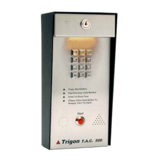
The resident then grants or denies access. The T.A.C. 500 has a capacity of up to 400 telephone numbers and up to 400 personal entry codes, and is PBX 1 10 VA C compatible. -
Page 4: Mounting
T.A.C. 500 MOUNTING MOUNTING MOUNTING MOUNTING MOUNTING Arrangements must be made for the installation of a T.A.C. 500 Back & Bottom Plate standard voice-grade telephone line (touch-tone or Figure 2 5.60" rotary, telco or PBX Port), as close to the unit mounting location as possible. -
Page 5: Wiring Diagram
T.A.C. 500 WIRING DIAGRAM WIRING DIAGRAM WIRING DIAGRAM WIRING DIAGRAM WIRING DIAGRAM Alar m Shunt Input Main Relay Pow er Rel ay Telco 2 3 4 5 6 7 8 9 10 Figure 3 Page 5... -
Page 6: System Setup
Note: Adding TWO to the Dial Mode selection allows Enter Resident Code Length: the keypad of the T.A.C. 500 to remain active for use This will be the number visible on the directory used by with voice-mail/automated attendant systems, after the a visitor to locate a resident. -
Page 7: Programming
You will hear two beeps. The unit is now ready to You will hear two beeps, indicating the number has been program. recorded in the T.A.C. 500’s memory. (B) Adding Telephone Numbers: Repeat steps 2 and 3 until you are finished. -
Page 8: Entering Access Cards
Identification Code makes it possible for the party possible for the user to use an access card at the unit and receiving a call from a T.A.C. 500 to identify which gain entry. Each card entered is converted to a standard “gate”... -
Page 9: Programming Primary Relay "On" Time
3. Enter Start Time (Use military format of This procedure allows selective or complete deletion of hours:minutes, i.e. “0600” , “1500”). Entry must be all data in the T.A.C. 500’s memory. Also, it is possible four digits. to reset the T.A.C. 500 back to its factory defaults 4. -
Page 10: Operation
Unlatch Door / Gate manual. To latch (hold closed) a relay, place a telephone (Optional) call to the T.A.C. 500. The T.A.C. 500 will auto-answer and you will hear a brief tone in the speaker. Refer to Latch secondary device (camera etc.) Fig. -
Page 11: Remote Operation Time-Out
Printer Operation: (Optional) If you call the unit to operate it remotely, you have 30 The T.A.C. 500 can support an audit log output to a seconds until auto-termination. Any tone instruction remote serial printer up to 300 feet away. -
Page 12: Trouble Shooting
T.A.C. 500 TROUBLE SHOOTING GUIDE TROUBLE SHOOTING GUIDE TROUBLE SHOOTING GUIDE TROUBLE SHOOTING GUIDE TROUBLE SHOOTING GUIDE LOSES MEMORY NO DIAL TONE 1. Electrical noise on power line. Install EMI/RFI 1. Check (check fuse) input power at unit. Should be filter. - Page 13 T.A.C. 500 General: [ 4] Verify Relay One Schedule (hhmm hhmm d d) ( = not set) Data between [ ] is a mandatory program key stroke sequence. Data between { } is to be supplied by the [ 5} Verify Secondary relay schedule programmer.
-
Page 14: Specifications / Features
T.A.C. 500 SPECIFICATIONS / FEATURES SPECIFICATIONS / FEATURES SPECIFICATIONS / FEATURES SPECIFICATIONS / FEATURES SPECIFICATIONS / FEATURES Design- Handsfree telephone with programmable internal auto dial capability and remote control of relays. Capacity - 24, 50, 125, 300, or 400 residents. - Page 15 T.A.C. 500 Page 15...
- Page 16 T.A.C. 500 Page 16...
Need help?
Do you have a question about the T.A.C. 500 and is the answer not in the manual?
Questions and answers