Table of Contents
Advertisement
Quick Links
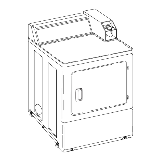
Clothes Dryer
Nonmetered and Metered
Electric and Gas Models
D677I
Para bajar una copia de estas instrucciones en español, visite www.comlaundry.com.
Keep These Instructions for Future Reference.
(If this machine changes ownership, this manual must accompany machine.)
Part No. 512680R2
www.comlaundry.com
July 2007
Advertisement
Table of Contents

Related Manuals for Alliance Laundry Systems continuity


Summary of Contents for Alliance Laundry Systems continuity
- Page 1 Clothes Dryer Nonmetered and Metered Electric and Gas Models D677I Para bajar una copia de estas instrucciones en español, visite www.comlaundry.com. Keep These Instructions for Future Reference. (If this machine changes ownership, this manual must accompany machine.) Part No. 512680R2 www.comlaundry.com July 2007...
- Page 3 • A “T-Handle” type gas shut-off valve must be installed in the gas supply line to this appliance. • This appliance must not be installed in a bedroom or bathroom. 512680 © Copyright, Alliance Laundry Systems LLC – DO NOT COPY or TRANSMIT...
-
Page 4: Table Of Contents
All rights reserved. No part of the contents of this book may be reproduced or transmitted in any form or by any means without the expressed written consent of the publisher. © Copyright, Alliance Laundry Systems LLC – DO NOT COPY or TRANSMIT 512680... - Page 5 Control Panel ................... 45 Exhaust System ................45 Lint Filter ....................46 Motor Overload Protector..............46 For Energy Conservation..............46 Troubleshooting .................. 47 Contact Information................48 Installer Checklist..............Back Cover © Copyright, Alliance Laundry Systems LLC – DO NOT COPY or TRANSMIT 512680...
-
Page 6: Safety Information
12. ALWAYS clean the lint filter after every load. A layer of lint in the filter reduces drying efficiency and prolongs drying time. 512680 © Copyright, Alliance Laundry Systems LLC – DO NOT COPY or TRANSMIT... - Page 7 Always contact your dealer, distributor, service agent or the manufacturer about any problems or conditions you do not understand. © Copyright, Alliance Laundry Systems LLC – DO NOT COPY or TRANSMIT 512680...
-
Page 8: Installation
(1.02 cm) 15.4 in. (59.7 cm) (71.1 cm) (39.1 cm) 26.9 in. (68.3 cm) GAS MODELS DRY2099N *With leveling legs turned into base. 3/8 in. N.P.T. Gas Connection 512680 © Copyright, Alliance Laundry Systems LLC – DO NOT COPY or TRANSMIT... -
Page 9: Metered Models
For maximum housing. drying performance, we recommend that more clearance be allowed around the dryer than the clearances that are listed throughout this manual. © Copyright, Alliance Laundry Systems LLC – DO NOT COPY or TRANSMIT 512680... -
Page 10: Before You Start
Figure 2 for coin operated MDC and NetMaster models. WARNING Any disassembly requiring the use of tools must be performed by a suitably qualified service person. W299 © Copyright, Alliance Laundry Systems LLC – DO NOT COPY or TRANSMIT 512680... -
Page 11: Installing The Dryer
The dryer must not rock. D678I D678I Dryer Base Level Leveling Leg Rubber Foot Figure 3 © Copyright, Alliance Laundry Systems LLC – DO NOT COPY or TRANSMIT 512680... - Page 12 Outer Wall of Enclosure **NOTE: For new installations, locate top of wall vent 42 inches (106.7 cm) above floor to make venting easier to connect. Figure 4 © Copyright, Alliance Laundry Systems LLC – DO NOT COPY or TRANSMIT 512680...
-
Page 13: Step 2: Connect Dryer Exhaust System
• Dryer exhausts 220 cfm (measured at back of dryer). • DO NOT install flexible duct in concealed spaces, such as a wall or ceiling. © Copyright, Alliance Laundry Systems LLC – DO NOT COPY or TRANSMIT 512680... -
Page 14: Exhaust Direction
IMPORTANT: DO NOT block the airflow at the bottom of the dryer’s front panel with laundry, rugs, etc. Blockage will decrease airflow through the dryer, thus reducing the efficiency of the dryer. © Copyright, Alliance Laundry Systems LLC – DO NOT COPY or TRANSMIT 512680... -
Page 15: Exhaust System
25 feet (7.6 m) 17 feet (5.2 m) 20 feet (6.1 m) 15 feet (4.5 m) NOTE: Deduct 6 feet (1.8 m) for each additional elbow. Table 1 © Copyright, Alliance Laundry Systems LLC – DO NOT COPY or TRANSMIT 512680... -
Page 16: Multi-Dryer Installation Exhaust Requirements
58786 Backdraft Damper (Available through Weather Hood or Sweep Elbow your local authorized parts source) (No cap or screen) Clean Out Cover (Must be provided). Inspect monthly. Figure 6 © Copyright, Alliance Laundry Systems LLC – DO NOT COPY or TRANSMIT 512680... - Page 17 2 in. (5 cm) Minimum NOTE: Where the exhaust duct pierces a combustible wall or ceiling, an opening must be sized as shown or per local codes. Figure 8 © Copyright, Alliance Laundry Systems LLC – DO NOT COPY or TRANSMIT 512680...
-
Page 18: Step 3: (Gas Dryer Only) Connect Gas Supply Pipe
• Do not use an open flame to check for gas leaks. Use a non-corrosive leak detection fluid. • Any disassembly requiring the use of tools must be performed by a suitably qualified service person. W316 © Copyright, Alliance Laundry Systems LLC – DO NOT COPY or TRANSMIT 512680... -
Page 19: Step 4: (Electric Dryer Only) Connect Electrical Plug
For proper operation at altitudes above 3500 feet (1070 m) the L.P. gas valve spud orifice size must be reduced to ensure complete combustion. Refer to Table 3. © Copyright, Alliance Laundry Systems LLC – DO NOT COPY or TRANSMIT 512680... - Page 20 Type of power cord and listed on the nameplate. Do not connect dryer gauge of wire must conform to local codes. to 110, 115, or 120 volt circuit. © Copyright, Alliance Laundry Systems LLC – DO NOT COPY or TRANSMIT 512680...
- Page 21 Ground to Neutral Wire Neutral Terminal “L2” Terminal Center Wire (Neutral) Strain Relief (Not supplied with dryer) Ground Screw “L1” Terminal Black Wire White Wire (Neutral) Red Wire Figure 11 © Copyright, Alliance Laundry Systems LLC – DO NOT COPY or TRANSMIT 512680...
- Page 22 3. Use a strain relief and insert end of power cord through power supply hole. 2. Remove access cover from rear of dryer. D696I D695I Figure 14 Figure 13 © Copyright, Alliance Laundry Systems LLC – DO NOT COPY or TRANSMIT 512680...
- Page 23 8. Reinstall access cover and screw. © Copyright, Alliance Laundry Systems LLC – DO NOT COPY or TRANSMIT 512680...
- Page 24 10. Reinstall access cover and screw. © Copyright, Alliance Laundry Systems LLC – DO NOT COPY or TRANSMIT 512680...
-
Page 25: Step 5: Reverse Door, If Desired
3. Pull bottom of door liner out, then pull down, removing door liner from door panel. DRY1918N DRY1918N Figure 26 7. Reinstall nine screws removed in Step 2. DRY1916N DRY1916N Figure 23 DRY1919N DRY1919N Figure 27 © Copyright, Alliance Laundry Systems LLC – DO NOT COPY or TRANSMIT 512680... -
Page 26: Step 6: Wipe Out Inside Of Dryer
• Do not use an extension cord. • Do not operate both a washer and gas dryer on D604I the same circuit. Use separetely fused 15 amp D604I circuits. Figure 30 © Copyright, Alliance Laundry Systems LLC – DO NOT COPY or TRANSMIT 512680... - Page 27 NOTE: Have a qualified electrician check the polarity of the wall receptacle. If a voltage reading is measured other than that illustrated, the qualified electrician should correct the problem. © Copyright, Alliance Laundry Systems LLC – DO NOT COPY or TRANSMIT 512680...
-
Page 28: Step 8: Recheck Steps 1-7
D700I D700I Closed Position 1/8 in. (3.1 mm) Pipe Plug Shut-Off Valve Handle (For checking manifold pressure) Air Shutter Lockscrew Open Position Air Shutter Figure 33 © Copyright, Alliance Laundry Systems LLC – DO NOT COPY or TRANSMIT 512680... -
Page 29: Vending
The timer will not count down until the Start button is pressed. Run Mode In Run Mode, the control is running a cycle. The IN USE LED is lit. © Copyright, Alliance Laundry Systems LLC – DO NOT COPY or TRANSMIT 512680... -
Page 30: Error Display Mode
To change the heat or cool down time for a coin pulse, the desired dry time dipswitches must be set to ON position. All other dipswitches must be in OFF position. © Copyright, Alliance Laundry Systems LLC – DO NOT COPY or TRANSMIT 512680... -
Page 31: Dipswitch Settings
Vending Dipswitch Settings Heat Switch Number Heat Time Per Coin Pulse (in minutes) Table 4 (continued) © Copyright, Alliance Laundry Systems LLC – DO NOT COPY or TRANSMIT 512680... - Page 32 42 (preset at factory) Cool Down Per Cycle Cool Down Switch Number (in minutes) 3 (preset at factory) Table 4 Total Cycle Time = Heat Time + Cool Down Time © Copyright, Alliance Laundry Systems LLC – DO NOT COPY or TRANSMIT 512680...
-
Page 33: Test Setting
Then set them all to the off position. Refer to Figure 34. 5. Plug in the machine. 1 2 3 4 5 6 7 8 DRY2225P DRY2225P Figure 34 © Copyright, Alliance Laundry Systems LLC – DO NOT COPY or TRANSMIT 512680... -
Page 34: Slide Extension
(shims) (use number of washers included in kit) and nut. Refer to Figure 36. Make sure washers are flat against bracket. © Copyright, Alliance Laundry Systems LLC – DO NOT COPY or TRANSMIT 512680... - Page 35 The IN USE light will turn on, or flash if it is already on, to indicate proper operation. NOTE: To avoid long run-down time (45 minutes factory default) when testing operation, refer to Test Setting section. © Copyright, Alliance Laundry Systems LLC – DO NOT COPY or TRANSMIT 512680...
-
Page 36: Additional Dryer Security
Double “D” Hole IMPORTANT: Do not use a power driver to tighten screw. Torque of a power driver could over-tighten Figure 39 screw causing damage to cabinet assembly. © Copyright, Alliance Laundry Systems LLC – DO NOT COPY or TRANSMIT 512680... -
Page 37: Operation
D609I Figure 41 Step 3: Close Loading Door Close loading door. Dryer will not operate with the door open. D608I D608I Figure 40 D688I D688I Figure 42 © Copyright, Alliance Laundry Systems LLC – DO NOT COPY or TRANSMIT 512680... -
Page 38: Step 4: Set Fabric Selector
18 hours or until door is 60 minutes). Press the PUSH-TO-START button. opened. IN USE light will come on (indicating start of cycle). NONMETERED MODELS DRY2101N Figure 44 © Copyright, Alliance Laundry Systems LLC – DO NOT COPY or TRANSMIT 512680... -
Page 39: Operation Instructions For Electronic Display Control Dryers
IMPORTANT: To avoid damage to dryer, do not use more than one fabric softener sheet per load. D294I D294I Figure 49 D609I D609I Figure 47 © Copyright, Alliance Laundry Systems LLC – DO NOT COPY or TRANSMIT 512680... -
Page 40: Step 5: Insert Coin(S) Or Card
Remove knits when slightly damp because overdyring may cause shrinkage. Do not tumble dry knit woolens. © Copyright, Alliance Laundry Systems LLC – DO NOT COPY or TRANSMIT 512680... - Page 41 Refer to portion of a heated cycle is active. It is also lit when Maintenance section. the NO HEAT cycle is in operation. © Copyright, Alliance Laundry Systems LLC – DO NOT COPY or TRANSMIT 512680...
-
Page 42: Operation Instructions For Mdc Dryers
D609I Figure 54 Step 3: Close Loading Door Close loading door. Dryer will not operate with the door open. D608I D608I Figure 53 D688I D688I Figure 55 © Copyright, Alliance Laundry Systems LLC – DO NOT COPY or TRANSMIT 512680... -
Page 43: Step 4: Set Fabric Selector
COOL DOWN is lit whenever the COOL DOWN portion of a heated cycle is active. It is also lit when no heat is programmed for a cycle in operation. DRY1927N Figure 58 © Copyright, Alliance Laundry Systems LLC – DO NOT COPY or TRANSMIT 512680... -
Page 44: Operation Instructions For Netmaster Dryers
IMPORTANT: To avoid damage to dryer, do not D777I use more than one fabric softener sheet per load. D777I Figure 63 D609I D609I Figure 61 © Copyright, Alliance Laundry Systems LLC – DO NOT COPY or TRANSMIT 512680... -
Page 45: Step 5: Insert Coin(S) Or Card
Remove knits when slightly damp because overdrying may cause shrinkage. Do not tumble dry knit woolens. © Copyright, Alliance Laundry Systems LLC – DO NOT COPY or TRANSMIT 512680... -
Page 46: Indicator Lights
(HIGH TEMP, MED TEMP, or LOW TEMP) is currently in operation. DRYING will turn off at the end of a heated cycle or when the COOL DOWN cycle begins. © Copyright, Alliance Laundry Systems LLC – DO NOT COPY or TRANSMIT 512680... -
Page 47: Maintenance
NOTE: The wiring diagram is located inside the control panel. WARNING Label all wires prior to disconnection when servicing controls. Wiring errors can cause improper and dangerous operation. W049 © Copyright, Alliance Laundry Systems LLC – DO NOT COPY or TRANSMIT 512680... -
Page 48: Lint Filter
PUSH-TO-START button or START pad. If overload protector cycles again, remove the dryer from use and call the service person to correct the problem. © Copyright, Alliance Laundry Systems LLC – DO NOT COPY or TRANSMIT 512680... -
Page 49: Troubleshooting
Check room for odors before drying clothes. Any odor (fried foods, paint, Clothes have odor varnish, cleaners, burning wood, etc.) will transfer to clothing as the dryer draws air from the room. Ventilate room before drying clothes. © Copyright, Alliance Laundry Systems LLC – DO NOT COPY or TRANSMIT 512680... -
Page 50: Contact Information
The nameplate will be in the location shown in the illustration below. Please include a copy of your bill of sale and any service receipts you have. D063K Nameplate Figure 68 512680 © Copyright, Alliance Laundry Systems LLC – DO NOT COPY or TRANSMIT... -
Page 52: Installer Checklist
Installer Checklist Fast Track for Installing the Dryer (Refer to the manual for more detailed information) • Position and • Wipe Out Inside of Level the Dryer. Dryer. LEVEL D255I D255I D256I CHECK CHECK D610I D610I D259I • Connect Dryer Exhaust System. •...
Need help?
Do you have a question about the continuity and is the answer not in the manual?
Questions and answers