Toa SX-2000 SERIES Installation Manual
Matrix system
Hide thumbs
Also See for SX-2000 SERIES:
- Operating instructions manual (132 pages) ,
- Firmware update procedure (12 pages) ,
- Installation manual (16 pages)
Table of Contents
Advertisement
MATRIX SYSTEM
thank you for purchasing toA's matrix System.
Please carefully follow the instructions in this manual to ensure long, trouble-free use of your equipment.
When an EN 54-16 compliant SX-2000 system has to be installed, then read "APPENDIX: ADDItIoNAl
INStAllAtIoN INStructIoNS for AN EN 54-16 comPlIANt SyStEm" in this document carefully
and follow up the installation and configuration requirements explained herein. this APPENDIX contains
the basic description of settings and installations, so please refer to the general instruction sections in this
document for more details.
Note
refer to the Instruction manual attached to the VX-2000DS/3000DS for the installation of the the VX-
2000DS or VX-3000DS Emergency power supply, the VX-2000Pf Power supply frame, and the VX-200PS
Power supply unit.
TOA Electronics Europe GmbH
Suederstrasse 282, 20537 Hamburg, Germany
1134-CPR-102
DoP 14-003
EN 54-16: 2008
Fire detection and fire alarm systems
— Part 16: Voice alarm control and indicating equipment
Emergency microphone(s)
Manual reset of the voice alarm condition
Indication of faults related to voice alarm zones
Phased evacuation
Voice alarm condition output to CIE
Redundant power amplifiers
INSTALLATION MANUAL
SX-2000 SERIES
1134
14
Options:
Advertisement
Table of Contents

Related Manuals for Toa SX-2000 SERIES


Summary of Contents for Toa SX-2000 SERIES
- Page 1 INSTALLATION MANUAL MATRIX SYSTEM SX-2000 SERIES thank you for purchasing toA's matrix System. Please carefully follow the instructions in this manual to ensure long, trouble-free use of your equipment. 1134 TOA Electronics Europe GmbH Suederstrasse 282, 20537 Hamburg, Germany 1134-CPR-102...
-
Page 2: Table Of Contents
TABLE OF CONTENTS 1. NOMENCLATURE AND FUNCTIONS ..........6 1.1. SX-2000Sm System manager ................6 1.2. SX-2000AI Audio Input unit ................10 1.3. SX-2100AI Audio Input unit ................. 15 1.4. SX-2000Ao Audio output unit ................20 1.5. SX-2100Ao Audio output unit ................ - Page 3 2.5.8. Installing the rm-200Sf on a wall ............77 2.5.9. rm-200SA expansion with the addition of the rm-210 (Installed on a flat surface) ............... 81 2.5.10. Installing the rm-200SA on a wall ............82 2.5.11. Installing the rm-210 on a wall ..............
- Page 4 5. SpEAKER LINE INITIAL SETTINg ........... 140 5.1. Setting Items ..................... 140 5.2. oPEN/SHort criterion by comparing the current Value with the Initial Value ..................140 5.3. Setting Procedures ................... 141 5.3.1. Summary setting procedures ..............141 5.3.2. Screen display (common) ..............
- Page 5 11.19. VP-2122 Power Amplifier 2 x 120 W ............. 176 11.20. VP-2241 Power Amplifier 1 x 240 W ............. 177 11.21. VP-2421 Power Amplifier 1 x 420 W ............. 178 11.22. VP-3154 Digital Power Amplifier 4 x 150 W ..........179 11.23.
-
Page 6: Nomenclature And Functions
SX-2000SM 1. NOMENCLATURE AND FUNCTIONS 1.1. SX-2000SM System Manager [Front] 10 11 12 Protective cover Inside of the protective cover 15 16 1. LAN Indicator [LAN] (green) emergency cutoff input terminal and is cut off lights when the lAN connection terminal (31) on (24 V emergency cutoff function) in emergency the rear panel is connected, and flashes during situations. - Page 7 SX-2000SM 8. CpU Indicator [CpU] (Yellow) 18. CF Card Slot [CF CARD] lights while the general urgency all-call is being use this slot to insert the cf card to operate made 70) or when a failure is detected in settings data or write log data to the card. the SX-2000Sm.
- Page 8 SX-2000SM [Rear] 25 26 31 32 20. Functional Earth Terminal [SIgNAL gND] • CpU FAULT Hum noise may be generated when external cPu irregularity in progress: equipment is connected to the unit. connecting Pin 1 – Pin 2 shorted this terminal to the functional earth terminal of the Normal: Pin 1 –...
- Page 9 • After connection completion, press the Reset becomes approximately 24 V Dc when opened. key to reactivate the SX-2000Sm. • ACK * contact your toA dealer for more information the buzzer may sound when a failure is detected on switching hubs. in the SX-2000Sm.
-
Page 10: Sx-2000Ai Audio Input Unit
SX-2000AI 1.2. SX-2000AI Audio Input Unit [Front] 4 5 6 7 8 9 10 Protective cover Inside of the protective cover 1. Monitor Speaker 5. Cancel Key [ /CANCEL] Allows any input channel to be monitored. used to switch the menu screen. 2. - Page 11 SX-2000AI 11. Standby Indicator [STANDBY] (green) 16. USB port [USB] lights while the unit is being initialized at power- this port is not used. on or at reset. Flashes when the fluorescent display is in light 17. RUN Indicator [RUN] (green) shutoff mode and the light stays unlit.
- Page 12 SX-2000AI [Fluorescent Display] KEYLOCK FAULT EMERGENCY FADER –10 –10 –20 –20 –30 –30 LEVEL LEVEL –40 –40 22 23 24 25 34 35 36 Notes • A timer-activated light shutoff function can be set for the fluorescent display using the SX-2000 Setting Software.
- Page 13 SX-2000AI 33. Remote Microphone Connection Status 35. Monitor Level Meter Scale Indicator lights when the monitor oN/off key (15) is set the device number of the remote microphone to oN. connected to the SX-2000AI lights. 36. Monitor ON/OFF Indicator [LEvEL] 34.
- Page 14 Notes • Be sure to connect both terminals of A and B. • After connection completion, press the Reset key to reactivate the SX-2000AI. * contact your toA dealer for more information on switching hubs. Function LED On/Flashing LED Off 1.
-
Page 15: Sx-2100Ai Audio Input Unit
SX-2100AI 1.3. SX-2100AI Audio Input Unit [Front] 4 5 6 7 8 9 10 Protective cover Inside of the protective cover 1. Monitor Speaker 5. Cancel Key [ /CANCEL] Allows any input channel to be monitored. used to switch the menu screen. 2. - Page 16 SX-2100AI 11. Standby Indicator [STANDBY] (green) 16. USB port [USB] lights while the unit is being initialized at power- this port is not used. on or at reset. Flashes when the fluorescent display is in light 17. RUN Indicator [RUN] (green) shutoff mode and the light stays unlit.
- Page 17 SX-2100AI [Fluorescent Display] KEYLOCK FAULT EMERGENCY FADER –10 –10 –20 –20 –30 –30 LEVEL LEVEL –40 –40 22 23 24 25 34 35 Notes • A timer-activated light shutoff function can be set for the fluorescent display using the SX-2000 Setting Software.
- Page 18 SX-2100AI 33. Remote Microphone Connection Status 35. Monitor Level Meter Scale Indicator lights when the monitor oN/off key (15) is set the device number of the remote microphone to oN. connected to the SX-2100AI lights. 36. Monitor ON/OFF Indicator [LEvEL] 34.
- Page 19 SX-2100AI. 2 mA for the loop current. Since each terminal is equipped with a current limiter employing * contact your toA dealer for more information constant current circuitry, there is no need to limit on switching hubs.
-
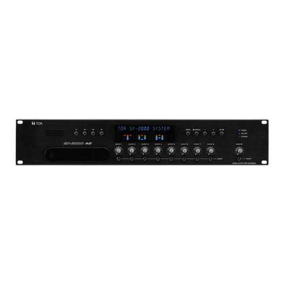
Page 20: Sx-2000Ao Audio Output Unit
SX-2000AO 1.4. SX-2000AO Audio Output Unit [Front] 4 5 6 7 8 Protective cover Inside of the protective cover 1. Monitor Speaker 5. Cancel Key [ /CANCEL] Allows any output channel to be monitored. used to switch the menu screen. 2. - Page 21 SX-2000AO 11. Standby Indicator [STANDBY] (green) 16. USB port [USB] lights while the unit is being initialized at power- this port is not used. on or at reset. Flashes when the fluorescent display is in light 17. RUN Indicator [RUN] (green) shutoff mode and the light stays unlit.
- Page 22 SX-2000AO [Fluorescent Display] KEYLOCK FAULT EMERGENCY FADER –10 –10 –20 –20 –30 –30 LEVEL LEVEL –40 –40 31 32 33 34 35 36 22 23 24 25 26 Notes • A timer-activated light shutoff function can be set for the fluorescent display using the SX-2000 Setting Software.
- Page 23 SX-2000AO Note 33. Control Output Unit Connection Indicator [2] When the 24 V Emergency cutoff input is set to be Indicates "2" when the SX-2000co is connected disabled (not usable) with the DIP switch 8 inside to the SX-2000Ao. the protective cover, the Emergency indicator 34.
- Page 24 SX-2000AO 41. Isolation Jumper 2 [gND] 44. Isolation Jumper 1 [gND] the supplied removable terminal plug is equipped the supplied removable terminal plug is equipped with a jumper. with a jumper. When the jumper is attached, the [–] terminals of When the jumper is attached, the [–] terminals of control inputs 3, 4, 7, and 8 are connected to the control inputs 1, 2, 5, and 6 are connected to the...
- Page 25 Notes • Be sure to connect both terminals of A and B. • After connection completion, press the Reset key to reactivate the SX-2000Ao. * contact your toA dealer for more information Function LED On LED Off on switching hubs.
-
Page 26: Sx-2100Ao Audio Output Unit
SX-2100AO 1.5. SX-2100AO Audio Output Unit [Front] 4 5 6 7 8 Protective cover Inside of the protective cover 1. Monitor Speaker 5. Cancel Key [ /CANCEL] Allows any output channel to be monitored. used to switch the menu screen. 2. - Page 27 SX-2100AO 11. Standby Indicator [STANDBY] (green) 16. USB port [USB] lights while the unit is being initialized at power- this port is not used. on or at reset. Flashes when the fluorescent display is in light 17. RUN Indicator [RUN] (green) shutoff mode and the light stays unlit.
- Page 28 SX-2100AO [Fluorescent Display] KEYLOCK FAULT EMERGENCY FADER –10 –10 –20 –20 –30 –30 LEVEL LEVEL –40 –40 22 23 24 25 26 33 34 35 36 37 Notes • A timer-activated light shutoff function can be set for the fluorescent display using the SX-2000 Setting Software.
- Page 29 SX-2100AO 32. Local Audio Input Level Meter 35. Monitor Level Meter Indicates each level of signals applied to the local Indicates the sound volume level of the output audio inputs 1 and 2 while the local audio control channel being monitored. inputs 1 and 2 are activated, respectively.
- Page 30 SX-2100AO 41. Control Input Terminals 44. Isolation Jumper 1 [gND] [Control INput 1 – 8] the supplied removable terminal plug is equipped Photo coupler inputs. A current of approximately with a jumper. 2 mA flows when shorted, and the voltage When the jumper is attached, the [–] terminals of becomes under 40 V Dc when opened.
- Page 31 SX-2100Ao. terminal of the standby amplifier* use the VP-2000 series or VP-3000 series contact your toA dealer for more information amplifier. on switching hubs. 54. Speaker Connection Terminals [ZONE 1 – 8 Sp] connect these terminals to speakers.
-
Page 32: Sx-2000Ci Control Input Unit
SX-2000CI 1.6. SX-2000CI Control Input Unit [Front] POWER CPU OFF FAULT CONTROL INPUT CONTROL INPUT UNIT SX - 2000CI Protective cover Inside of the protective cover ID NUMBER RESET SETTING 1. Control Input Indicators 6. RUN Indicator [RUN] (green) [CONTROL INpUT 1 – 32] (green) Normally flashes continuously. - Page 33 SX-2000CI [Rear] 14 15 CONTROL INPUT CI/CO LINK DC 24V OUT THROUGH DATA MAX. 0.1A 10. Functional Earth Terminal [SIgNAL gND] 13. Control Input Terminals [CONTROL INput 1 – 32] Hum noise may be generated when external equipment is connected to the unit. connecting Photo coupler inputs.
-
Page 34: Sx-2000Co Control Output Unit
SX-2000CO 1.7. SX-2000CO Control Output Unit [Front] POWER CPU OFF FAULT CONTROL OUTPUT CONTROL OUTPUT UNIT SX - 2000CO Protective cover Inside of the protective cover ID NUMBER RESET SETTING 1. Control Output Indicators 5. USB port [USB] [CONTROL OUTpUT 1 – 32] (green) this port is not used. - Page 35 SX-2000CO [Rear] CONTROL OUTPUT C NC NO CI/CO LINK THROUGH DATA 10. Functional Earth Terminal [SIgNAL gND] 12. Control Output Terminals Hum noise may be generated when external [CONTROL OUTpUT 1 – 32] equipment is connected to the unit. relay make contact outputs. Each contact connecting this terminal to the functional earth capacity is rated at 40 V Dc for withstand voltage, terminal of the external equipment may reduce...
-
Page 36: Rm-200Sf Fireman's Microphone
RM-200SF 1.8. RM-200SF Fireman's Microphone [Top] RM-200SF FIREMAN'S MICROPHONE [Hand-held microphone] 1. power Indicator (green) 8. Indication Label Insert Slot lights when the power is turned on. the label can be printed using the SX-2000 Setting Software. (See the separate Setting 2. - Page 37 RM-200SF 12. Status Indicators (Red/Yellow/green) 15. Microphone Indicator (green) Light, flash, or go off depending on the current lights or goes off depending on the current operation state of function keys, failure state or operation state of the talk key. emergency state.
- Page 38 RM-200SF [Bottom] [wall mount bracket unit (Accessory)] DIP SWITCH UNIT ID COMMUNICATION LEVEL METER CPU OFF TERMINATION 20. DIp Switch [DIp SwITCh] 22. Extension Connector used for setting the rm-200Sf unit. connect this connector to the extension connector (23) of the Wall mount Bracket unit (accessory). •...
-
Page 39: Rm-200Sa Remote Microphone
RM-200SA 1.9. RM-200SA Remote Microphone [Top] RM-200SA 1. Microphone 6. Indication Label Insert Slots used for voice announcements. labels can be printed using the SX-2000 Setting Software. (See the separate Setting Software 2. power Indicator (green) Instructions, "Printing labels remote lights when the power is turned on. - Page 40 RM-200SA 10. Talk Key 11. Function Keys (L1 – L3) Press this key to broadcast a voice announcement. Positioned in top-down order (l1, l2, l3). If the talk key is set to "Ptt" ("press-to-talk") these keys operate in the same manner as the mode, then it must be pressed continuously for function keys (r1 –...
- Page 41 RM-200SA [Rear] 16. power Input Terminal [DC pOwER IN] connect an optional AD-246 Ac adapter to this terminal when extending cable length. Power is usually supplied to the rm-200SA and rm- 210 from the SX-200rm remote microphone Interface module. (See 109.) 17.
-
Page 42: Rm-210 Remote Microphone Extension
RM-210 1.10. RM-210 Remote Microphone Extension Note up to 5 rm-210 remote microphone Extensions can be connected to each rm-200Sf fireman's microphone. up to 4 rm-210 remote microphone Extensions can be connected to each rm-200SA remote microphone. [Top] 1. Indication Label Insert Slot the label can be printed using the SX-2000 Setting Software. -
Page 43: Rm-200Rj Terminal Unit
1.11. RM-200RJ Terminal Unit [Front] 1. RM Link Terminal [RM LINK] 4. Screw Terminal Block connect to the rm link terminal of the rm-200SA the Screw terminal block and rm link terminal or SX-200rm. are internally connected in parallel. Numbers through indicated beside each terminal 2. -
Page 44: Optional Modules
All of the inserte d modules cannot be recognized correctly when any module other than listed above is inserted into the SX-2000AI's or SX-2100AI's module slots. 1.12.1. SX-200RM Remote Microphone Interface Module FOR SX-2000 SERIES ONLY 1. gain Control Knobs [gAIN] Increase the audio level of the rm-200Sf or rm-200SA remote microphone by up to 12 dB. -
Page 45: D-921E Microphone/Line Input Module
1.12.2. D-921E Microphone/Line Input Module [–50 / –36 / –10 / +4 dB] MIC/LINE INPUT MODULE model D-921E 1. Monaural Input Terminals [1, 2] Electronically-balanced, removable terminal blocks. (H: Hot; c: cold; E: Ground) Input sensitivity (–50/–36/–10/+4 dB) and phantom power (+12 V) oN/off can be set by the SX-2000 Setting Software. -
Page 46: D-922E Microphone/Line Input Module
1.12.4. D-922E Microphone/Line Input Module MIC/LINE INPUT MODULE model D-922E 1. Monaural Input Terminals [1, 2] Electronically-balanced, removable terminal blocks. (H: Hot; c: cold; E: Ground) Note Be sure to use the supplied removable terminal plugs (3P) for connection. 2. Input Sensitivity Switches [phANTOM, gND LIFT, MIC/LINE] 4-pole switches. -
Page 47: D-936R Stereo Input Module
1.12.6. D-936R Stereo Input Module Notes • This module can only be used in the SX-2000 system for monaural input. • Make sure that the channels indicated on the module differ from those set for the SX-2000 STEREO SELECT INPUT MODULE [ –10 dB] model D-936R system. -
Page 48: Vp-2064, Vp-2122, Vp-2241, And Vp-2421 Power Amplifiers
1.13. vp-2064, vp-2122, vp-2241, and vp-2421 power Amplifiers four different configurations of power amplifiers can be used in the SX-2000 system: 60 W x 4 channels, 120 W x 2 channels, 240 W x1 channel, and 420 W x 1 channel versions. mount a VP-200VX Power Amplifier Input module for each channel used. -
Page 49: Vp-3154, Vp-3304, And Vp-3504 Power Amplifiers
1.15. vp-3154, vp-3304, and vp-3504 power Amplifiers three different configurations can be used in the SX-2000 system: 150 W x 4 channels, 300 W x 4 channels, and 500 W x 4 channels. Note the VP-3000 series amplifiers can be used in conjunction with the VX-3000DS only, but not with the VX- 2000DS. - Page 50 4. pA Link Connector [pA LINK] 6. BgM volume Control [vOL.] this rJ45 connector connects to the SX-2100Ao’s Adjusts the BGm input level. PA lINK (ZoNE 1 – 8, StANDBy) connector. If the PEAK indicator lights red, reduce the BGm output audio signals are transmitted to the power output level at the BGm source equipment or BGm amplifier, and the power amplifier’s audio monitor...
-
Page 51: Installation
2. INSTALLATION 2.1. SX-2000SM 2.1.1. System reset enable/disable settings (DIp switch 3 operation) the entire system can be reactivated by pressing the SX-2000Sm's reset key. It is also possible to enable the entire system to restart through the operation of System reset button on the SX-2000 Setting software. use the SX-2000Sm's DIP switch 3 to enable or disable the system reset function with the SX-2000 Setting software. -
Page 52: Failure Reset Operation Method Settings (Dip Switch 4 Operation)
2.1.2. Failure reset operation method settings (DIp switch 4 operation) one of the following 2 modes can be selected with the SX-2000Sm's DIP switch 4 to determine the operation method of the SX-2000Sm’s front-mounted fAult rESEt key and rear-mounted rES terminals of the Date input terminals. -
Page 53: Sx-2000Ai And Sx-2100Ai
2.2. SX-2000AI and SX-2100AI 2.2.1. Module installation Notes • Make sure that the power is switched OFF before attaching or detaching modules. • To avoid failures due to static electricity, do not touch the parts on the module circuit board. •... -
Page 54: Setting The Device Number
2.2.2. Setting the device number Notes • When setting the device number for multiple SX-2000AI and SX-2100AI units, assign different numbers to each unit. the device number that can be used must not exceed the actual number of SX-2000AI and SX- 2100AI units set using the SX-2000 Setting Software. -
Page 55: Changing The Type Of Control Outputs (Sx-2100Ai Only)
2.2.3. Changing the type of control outputs (SX-2100AI only) this change should only be performed by a qualified professional wARNINg electrician. If users open the unit case or modify the unit, this may cause fire or electric shock. All the contact outputs are of normally open type when shipped from the factory. Each output can be converted into normally closed type by changing the jumper setting on the cIo circuit board. - Page 56 Step 2. change the jumper settings on the cIo circuit board. The numbers at the jumper connectors below correspond to SX-2100AI the control output terminal numbers. CIO circuit board Rear panel side Jumper position for the normally open output (factory-preset) Note This figure shows an example when the control output 7 is changed into...
-
Page 57: Sx-2000Ao And Sx-2100Ao
2.3. SX-2000AO and SX-2100AO 2.3.1. Setting the device number Notes • When setting the device number for multiple SX-2000AO and SX-2100AO units, assign different numbers to each unit. the device number that can be used must not exceed the actual number of SX-2000Ao and SX- 2100Ao units set using the SX-2000 Setting Software. -
Page 58: Emergency Cutoff Input Settings (Dip Switch 8 Operation) (Sx-2000Ao Only)
2.3.2. 24 v Emergency cutoff input settings (DIp switch 8 operation) (SX-2000AO only) the 24 V Emergency cutoff input can be set to be enabled or disabled. once enabled when the SX-2000 system is combined with an emergency broadcast system, a 24 V Dc is normally kept being supplied to this 24 V emergency cutoff input terminal and is cut off (24 V emergency cutoff function) in emergency situations. -
Page 59: Converting An Output Into A Transformer-Balanced Output (Sx-2000Ao Only)
2.3.3. Converting an output into a transformer-balanced output (SX-2000AO only) this change should only be performed by a qualified professional wARNINg electrician. If users open the unit case or modify the unit, this may cause fire or electric shock. the output can be changed from an electronically-balanced output to a transformer-balanced output with the additional use of an optional It-450 transformer. - Page 60 Step 2. Remove the flat cable and connectors (10P and 11P) connected to the link circuit board. • Detaching a flat cable Front panel side to remove the flat cable, first raise the lock lever on top of the connector. SX-2000AO link circuit board Flat cable connector 10P connector Side view of the connector...
- Page 61 Front panel side SX-2000AO link circuit board IT-450 mounting position OUTPUT 8 OUTPUT 6 OUTPUT 2 OUTPUT 7 OUTPUT 4 OUTPUT 5 OUTPUT 1 OUTPUT 3 Example of how to cut jumpers when a transformer is installed in the place of Output 1 (T101). Step 4.
-
Page 62: Changing The Method Of Power Supply For The Control Input Signal Applied To The Local Audio Control Input Terminal (Sx-2100Ao Only)
2.3.4. Changing the method of power supply for the control input signal applied to the Local Audio Control Input Terminal (SX-2100AO only) this change should only be performed by a qualified professional wARNINg electrician. If users open the unit case or modify the unit, this may cause fire or electric shock. - Page 63 Step 2. change the jumper settings on the link circuit board. Note that the SJP901 is for the local Input 1, and the SJP-902 for the local Input 2. Front panel side SX-2100AO link circuit board Using the internal Using an external power supply power supply Local input 1...
-
Page 64: Sx-2000Co
2.4. SX-2000CO [Method to turn the control outputs on when the general urgency all-call is made] this change should only be performed by a qualified professional wARNINg electrician. If users open the unit case or modify the unit, this may cause fire or electric shock. - Page 65 Step 2. Perform DIP switch settings on the co circuit board. the control output channels correspond to the DIP switches on the co circuit board as follows. control output channels 1 – 8: SW301 control output channels 9 – 16: SW302 control output channels 17 –...
-
Page 66: Rm-200Sf, Rm-200Sa, And
2.5. RM-200SF, RM-200SA, and RM-210 2.5.1. RM-200SF and RM-200SA device number settings (DIp switches 1 – 3 operation) Set device numbers (ID numbers) using DIP switches 1 – 3 located on the bottom panel of the rm-200Sf and the side panel of the rm-200SA. DIP SWITCH UNIT ID COMMUNICATION... - Page 67 Device number DIP switch 3 DIP switch 2 DIP switch 1 RM-200SF RM-200SA (Default setting)
-
Page 68: Adjusting Microphone Sensitivity (Rm-200Sf: Dip Switch 5 Operation Or Rm-200Sa: Dip Switch 4 Operation)
2.5.2. Adjusting microphone sensitivity (RM-200SF: DIp switch 5 operation or RM-200SA: DIp switch 4 operation) Since the DIP switch can be set to make the broadcast status indicator show output signal level,* adjust the microphone sensitivity using the following procedure: * When the microphone is in use, the indicator shows the output signal level. - Page 69 Step 3. using the microphone volume control, adjust the microphone input sensitivity to an appropriate level (until the broadcast status indicator lights green). RM-200SF top RM-200SA rear RM-200SF FIREMAN'S MICROPHONE Microphone volume control Microphone volume control Step 4. Set DIP switch 5 of the rm-200Sf to off or DIP switch 4 of the rm-200SA to off. Note Be sure to set both DIP switches to off after adjusting the microphone input sensitivity.
-
Page 70: Cpu Off Function (General Urgency All-Call) Settings (Rm-200Sf: Dip Switch 6 Operation Or Rm-200Sa: Dip Switch 5 Operation)
2.5.3. CpU OFF function (general urgency all-call) settings (RM-200SF: DIp switch 6 operation or RM-200SA: DIp switch 5 operation) the cPu off function permits the all-zone calls to be made from the rm-200Sf or rm-200SA by bypassing the cPu* normally used by the SX-2000 system and using an analog link instead. this function is usually used if a system failure is preventing normal broadcasts from being made. -
Page 71: Rm Communication Function Setting (Rm-200Sf: Dip Switch 4 Operation Or Rm-200Sa: Dip Switch 6 Operation)
2.5.4. RM Communication function setting (RM-200SF: DIp switch 4 operation or RM-200SA: DIp switch 6 operation) Set the rm communication function to the Automatic Setting (off) or 9600 bps fixed (oN). Normally set to the Automatic Setting (off). communication may become unstable depending on conditions when cable length between the unit and remote microphone is great. -
Page 72: Using An External Microphone (Rm-200Sa Only)
2.5.5. Using an external microphone (RM-200SA only) this change should only be performed by a qualified professional wARNINg electrician. If users open the unit case or modify the unit, this may cause fire or electric shock. changing the jumper settings on the rm-200SA's circuit board causes an external microphone to be used. Notes •... - Page 73 Step 3. replace the rm-200SA's upper case. Note Note the types of screws when replacing the upper case (See Step 1.) [plug for connection to the RM-200SA's external input terminal] connect the microphone's signal line to the tip and its shield line to the sleeve of the stereo mini plug or monaural mini plug.
-
Page 74: Compressor Function Setting
2.5.6. Compressor function setting this change should only be performed by a qualified professional wARNINg electrician. If users open the unit case or modify the unit, this may cause fire or electric shock. the compressor function enables even large signals to be broadcast without distortion. (this function is factory- preset to oN.) Notes •... - Page 75 [RM-200SA] RM-200SA bottom Step 1. unscrew 8 screws indicated by arrows in the figure at right, then detach the rm-200SA's upper case. Note Note the types of screws. A: 3 x 8 tapping screw (white silver) .... 6 pieces B: 3 x 10 tapping screw (black) ....2 pieces Step 2.
-
Page 76: Microphone Fault Detection Function Setting (Rm-200Sa Only)
2.5.7. Microphone fault detection function setting (RM-200SA only) wARNINg this work should only be performed by a qualified professional electrician. If users open the unit case or modify the unit, this may cause fire or electric shock. the rm-200SA is equipped with the microphone fault detection function, which can be set to off. (factory- preset to oN) Notes •... -
Page 77: Installing The Rm-200Sf On A Wall
2.5.8. Installing the RM-200SF on a wall the rm-200Sf is designed for on-wall installation. [Mounting hardware] to mount the rm-200Sf on the wall, the following parts are required. Wall mount bracket unit .............. 1 (supplied with the rm-200Sf) Wall mounting screws 4 x 25 tapping screw for wooden wall ........ - Page 78 [Installation] Step 1. Install the wall mount bracket unit supplied with the rm-200Sf on the wall. 1-1. Installing directly on the wall Install the unit on the wall using 2 screws or more depending on the installation location. the rm-200Sf comes with 2 tapping screws 4 x 25 for direct wall mounting. wARNINg •...
- Page 79 (2) Slide the Bracket A as show below to detach it from the Bracket B. Bracket B Slide the Bracket A upward, then pull it toward you. Bracket A (3) Attach the Bracket B to the electrical box using 2 screws m3.5 x 20 supplied with the rm-200Sf. Screw holes for mounting to the electrical box (2 places) wARNINg...
- Page 80 Step 3. Plug the rm-200Sf's extension connector into the connector port on the wall mount bracket unit. Step 4. Attach the rm-200Sf unit to the wall mount bracket unit. RM-200SF Extension connector Wall mount bracket unit (supplied with the RM-200SF) Note When attaching the rm-200Sf unit, check that the extension connector is not pinched.
-
Page 81: Rm-200Sa Expansion With The Addition Of The Rm-210 (Installed On A Flat Surface)
2.5.9. RM-200SA expansion with the addition of the RM-210 (Installed on a flat surface) When adding an rm-210 remote microphone Extension to expand the rm-200SA, use the rm-210's Extension cable and included linkage Bracket to link the 2 microphones. After DIP switch setting completion, follow the procedures below. [Mounting hardware (supplied with the RM-210)] linkage Bracket A ........ -
Page 82: Installing The Rm-200Sa On A Wall
2.5.10. Installing the RM-200SA on a wall [Mounting hardware] to mount the rm-200SA on the wall, the following parts are required. Wall mounting bracket for the rm-210 (model WB-rm200) ..1 (optional) m3.5 x 20 screw for electrical box ..........2 (supplied with the WB-rm200) 4 x 25 tapping screw for wooden wall ........ -
Page 83: Installing The Rm-210 On A Wall
2.5.11. Installing the RM-210 on a wall [Mounting hardware] to mount the rm-210 on the wall, the following parts are required. Wall mounting bracket for the rm-210 (model WB-rm200) ..1 (optional) m3.5 x 20 screw for electrical box ..........2 (supplied with the WB-rm200) 4 x 25 tapping screw for wooden wall ........ - Page 84 Step 3. using the extension cable supplied with the rm-210, connect the rm-200Sf's or rm-200SA's side EXtENSIoN connector to the rm-210's side EXtENSIoN connector. Step 4. Hook the bottom surface of the rm-210 onto the WB-rm200. Extension cable (supplied with the RM-210) RM-210 RM-200SF Wall mounting bracket...
-
Page 85: Creating Remote Microphone Name Labels
2.5.12. Creating remote microphone name labels using the SX-2000 Setting Software function, assigned names of preset rm-200Sf, rm-200SA, and rm- 210 function keys can be printed out. once printed, cut out the printed names with scissors to use them as corresponding name labels. - Page 86 [If the name label is not printed correctly] the name label created using the SX-2000 Setting Software may not be printed in correct size depending on the configuration environment of your Pc. In such cases, try one of the methods described below. (1) Preparation by hand copy the "Pattern paper for hand writing"...
- Page 87 [pattern paper for hand writing] Name label A Name label B Name label C Cutting guideline Shown in actual size...
- Page 88 Name label B Name label B Name label B Name label B Shown in actual size Cutting guideline...
-
Page 89: Vp-2064, Vp-2122, Vp-2241 And Vp-2421 Power Amplifiers
100-volt line of speaker. for the methods using a 70- or 50-volt line, please consult your toA dealer. Step 1. Remove the top panel referring to the above figure. - Page 90 [Channel-to-connector relationship] model No. VP-2064 VP-2122 VP-2241 VP-2421 channel 1 cN102 cN102 cN102 cN102 channel 2 cN202 cN202 channel 3 cN302 channel 4 cN402 Step 3. change wiring. Disconnect a line and change it with the corresponding line. refer to the figure below when removing. to change to 50 V, change the Pin No.
-
Page 91: Installing The Vp-200Vx Power Amplifier Input Module In The Vp Power Amplifiers
2.6.3. Installing the vp-200vX power Amplifier Input Module in the vp power Amplifiers Step 1. remove the top panel. refer to p. 89, "Removing the VP Power Amplifier’s top panel" for removal procedures. Step 2. using nippers, clip out 4 connecting sections and the plate over the VP-200VX mounting location on the power amplifier's rear panel. - Page 92 Step 4. Plug the VP-200VX's connector into the corresponding channel connector on the circuit board inside the amplifier. [VP-2064 Connector position] CN406 CN306 CN206 CN106 DRIVE PCB Rear panel [VP-2122 Connector position] CN206 CN106 DRIVE PCB Rear panel [VP-2241/2421 Connector position] DRIVE PCB Rear panel [Channel-to-connector relationship]...
-
Page 93: Ground Lifting Using The Vp-200Vx Power Amplifier Input Module
2.6.4. ground lifting using the vp-200vX power Amplifier Input Module When operating the system, hum noise may be generated by a ground loop accidentally created in the system. the ground loop can be cut off with the Ground lift jumper connector setting on the VP-200VX board. wARNINg to access the Ground lift jumper connector, take out the internal VP-200VX from the VP amplifier. -
Page 94: Replacing The Blade Fuse
2.6.5. Replacing the blade fuse When the internal blade fuse blew, replace it with new one following the procedures below. wARNINg Be sure to switch off the system power before accessing to the internal fuse for replacement. for the method to switch off the power, refer to the Instruction manual attached to the VX-2000DS/3000DS. Step 1. -
Page 95: Vp-3154, Vp-3304 And Vp-3504 Power Amplifiers
Note the speaker line failure detection functions are designed to perform on a 100-volt line of speaker. for the methods using a 70- or 50-volt line, please consult your toA dealer. Step 1. remove the top panel. Step 2. Shift the speaker line voltage selector to the desired voltage position on the corresponding channel’s Pc board. -
Page 96: Ground Lifting
2.7.2. ground lifting Hum noise may be generated by a ground loop accidentally created through the PA link’s audio input. In this case, the ground loop can be cut by setting the ground lift, which can be performed on the pc board of PA link/BGm input board. -
Page 97: Bgm Input Sensitivity Setting
2.7.3. BgM input sensitivity setting The BGM input sensitivity can be changed from −10 dB* (factory-preset) to 0 dB*. modification can be performed on the pc board of PA link/BGm input board. Amplifier’s rear BGM input PA link/BGM input board Step 1. -
Page 98: Replacing The Fuse
2.7.4. Replacing the fuse When a fuse has blown, the corresponding channel status indicator on the unit’s front panel goes out. In this case, replace the fuse mounted on the channel pc board inside the unit. Step 1. remove the top panel. Step 2. -
Page 99: Wrack Mounting
2.8. Rack Mounting CAUTION the supplied rack-mounting screws can be used for the toA equipment rack only. Do not use them for other racks. failure to do so may cause personal injury. Note Because the VP amplifiers, VX-2000DS, and VX-2000Pf are heavy, use supporting runners (separately prepared) in the rack to safely mount and securely support the units. -
Page 100: System Configuration Example
3. SYSTEM CONFIgURATION EXAMpLE 3.1. System Configuration Example 1 RM-200SF SX-2100AI SX-2100AO Power amplifiers RM-200SA Zone 1 SX-200RM Zone 2 Zone 3 SX-2000SM SX-200RM Zone 4 Power amplifiers Zone 5 CF card Digital announcer D-922E (Setting/Log data) Zone 6 Control input 2 Zone 7 BGM 1... -
Page 101: System Configuration Example 2
3.2. System Configuration Example 2 RM-200SF SX-2100AI SX-2100AO RM-200SA Power amplifiers SX-200RM Zone 1 AD-246 Zone 2 RM-200RJ SX-200RM Zone 3 SX-2000SM Zone 4 Power amplifiers Digital announcer D-922E CF card Zone 5 (Setting/Log data) Zone 6 BGM1 D-936R Zone 7 BGM2 SW-HUB Zone 8... -
Page 102: Connections
4. CONNECTIONS 4.1. Removable Terminal plug Connection Notes • Use the screwdriver supplied with the SX-2000SM when connecting the removable terminal connector. • Do not use a micro screwdriver. Sufficient torque is not given to the screws when tightening them, and connections may not be secured. -
Page 103: Input Equipment Connections
4.2. Input Equipment Connections 4.2.1. Connections of SX-2100AO's Local audio control input terminals use StP category 5 straight cables for connections. the diagram below shows cable connections to the local audio control input terminal. Local audio control input terminals SX-2100AO SX-2100AO Local audio control input terminals (RJ45) - Page 104 [Connecting the SX-2100AO to the Ev-350p Digital Announcer] Local audio control input terminals SX-2100AO Local audio control input terminal SHIELD Terminal functions START/BINARY START/BINARY OUTPUT 2 ERROR EMER- GENCY 0.3A BUSY 1 BUSY 2 STOP OUTPUT 1 COM PLAY NC CLEAR EV-350P...
-
Page 105: Connecting The Sx-200Rm To The Rm-200Sf Or Rm-200Sa (Via Rm-200Rj As Needed)
SX-2000AI's or SX-2100AI's input channel number to the rm lINK terminal. (for the rm-200Sf and rm-200SA device number settings, see 66.) RM1 status LED RM2 status LED SX-200RM FOR SX-2000 SERIES ONLY RM-200SF RM-200SF FIREMAN'S MICROPHONE Terminal block Connection cable (with RJ45 connectors) - Page 106 Connecting the SX-200RM to the RM-200SF Terminal block RM-200SF bottom To SX-200RM Wall mount bracket unit (supplied with the RM-200SF) DIP SWITCH UNIT ID COMMUNICATION LEVEL METER CPU OFF TERMINATION Connection cable (with RJ45 connectors) RJ45 connector Cable color Cable color Wall mount bracket unit (supplied with the RM-200SF) pin No.
- Page 107 Connecting the SX-200RM to the RM-200SA RM-200SA rear Connection cable (with RJ45 connectors) To SX-200RM [when power is supplied from the SX-200RM] • The following table shows the maximum cable distance when STP Category 5 straight cable (with RJ45 connectors) is used. No.
- Page 108 1 with 2, 4 with 5, 3 with 6, and 7 with 8 as shown below. SX-200RM RM-200RJ FOR SX-2000 SERIES ONLY STP Category 5 straight cable Shield (with RJ45 connectors)
- Page 109 • When using a shielded CPEV cable but not the RM-200RJ, connect the cable to STP Category 5 straight cable (with rJ45 connectors) as follows. Pair 1 with 2, 3 with 6, 4 with 5, and 7 with 8. To SX-200RM To RM-200SA Over 4-pair shielded CPEV cable (main cable)
-
Page 110: Connecting Other Input Equipment
4.2.3. Connecting other input equipment connect input equipment to the following modules installed in the SX-2000AI or SX-2100AI. [Microphone/Line Input Modules D-921F and D-922F] connect microphones or other sound sources with line outputs using 2-core shielded cables. MIC/LINE INPUT MODULE [–50 / –36 / –10 / +4 dB] model D-921F MIC/LINE INPUT MODULE model D-922F... - Page 111 [Stereo Input Module D-936R] connect BGm players or other sound sources to this module. Monaural input 1 Monaural input 2 STEREO SELECT INPUT MODULE [ –10 dB] model D-936R Note Since this module is equipped with 2 monaural input channels, connect a different sound source to each input. When using a stereo sound source, convert the stereo output to monaural first and connect it to one of the two inputs.
-
Page 112: Output Equipment Connections
4.3. Output Equipment Connections 4.3.1. Connecting the SX-2000AO to power amplifiers connect each output channel (broadcast zone) to the corresponding power amplifier. SX-2000AO Audio output terminals Audio lines (2-core shielded cables) To each channel's assigned power amplifier 12P removable terminal plug (supplied with the SX-2000AO) To each channel's assigned power amplifier... -
Page 113: Connecting The Sx-2100Ao To Power Amplifiers And Speakers
4.3.2. Connecting the SX-2100AO to power amplifiers and speakers connect each output channel (broadcast zone) to the corresponding power amplifier, and connect the power amplifier's output to the SX-2100Ao's amplifier input terminal, then connect speakers to the SX-2100Ao's speaker output terminal. [Connection example: when connecting the vp-2064 to the ZONE 1] SX-2100AO Audio signal output... - Page 114 [Connection example: when connecting the vp-3304 to the ZONE 1] SX-2100AO Audio signal output Control output Amplifier intput terminal To (A) 8P removable terminal plug Applicable cable: AWG 16 – 24 (supplied with the SX-2100AO) Applicable cable: CAT5-STP To speakers BGM player From (A) PA OUT (SP LINE)
- Page 115 [Connection example: when connecting the vp-3304 to the ZONE 1] (In the case shielded cables are used) SX-2100AO Audio signal output Control output Amplifier intput terminal To (A) 8P removable terminal plug Applicable cable: AWG 16 – 24 (supplied with the SX-2100AO) Applicable cable: CAT5-STP To speakers...
-
Page 116: Connecting The Sx-2100Ao To External Attenuators
4.3.3. Connecting the SX-2100AO to external attenuators DC POWER Supply (–) Control output terminals (–) Attenuator Relay Control Note SX-2100AO the attenuator is assumed to be bypassed when the power is supplied to the attenuator relay control. 6P removable terminal plug (supplied with the SX-2100AO) Speaker connection terminals and amplifier input terminals... -
Page 117: Connecting The Sx-2100Ao To Standby Amplifiers
4.3.4. Connecting the SX-2100AO to standby amplifiers [when vp-2241 is used] SX-2100AO Standby amplifier audio output terminal Standby amplifier intput terminal 2P removable terminal plug (supplied with the SX-2100AO) Applicable cable: AWG 16 – 24 Applicable cable: CAT5-STP PA OUT (SP LINE) PA LINK VP-200VX Amplifier Input Module VP-200VX... - Page 118 [when vp-3504 is used] SX-2100AO Standby amplifier audio output terminal Standby amplifier intput terminal 2P removable terminal plug (supplied with the SX-2100AO) Applicable cable: AWG 16 – 24 Applicable cable: CAT5-STP PA OUT (SP LINE) H C H C H C H C CH4 CH3 CH2 CH1 PA LINK Amplifier output terminal...
-
Page 119: Control Input/Output Connections
4.4. Control Input/Output Connections 4.4.1. SX-2000SM [Connecting control input terminals to the TT-104B program timer] this connection allows timer-activated automatic broadcasts. When the tt-104B's preprogrammed time is reached, the SX-2000Sm receives a control output signal (make contact) from the tt-104B and activates preset broadcast patterns. OUTPUT CHANNEL (24 V DC 0.5 A) TT-104B OUTPUT CHANNEL (24 V DC 0.5 A) - Page 120 [Connecting control output terminals to the Ev-350R Digital Announcer] this connection remotely activates external connected sound sources. When a broadcast is started, the SX-2000Sm provides a make contact to activate the EV-350r. 12P removable terminal plug (supplied with the SX-2000SM) Withstand voltage: 40 V DC Control current: 2 –...
-
Page 121: Sx-2100Ai
4.4.2. SX-2100AI [Connecting control input terminals to the TT-104B program timer] Since the SX-2100AI's control inputs are photo coupler inputs, they need a power supply. Power can be supplied to the photo couplers using the SX-2100AI's internal power supply or external power supply. •... - Page 122 • Since the control input terminals use photo couplers, they can be isolated using an external power supply source. remove the power feed jumper and isolation jumper installed on the 16P removable terminal plugs, then make connections as shown below: OUTPUT CHANNEL (24 V DC 0.5 A) TT-104B OUTPUT CHANNEL (24 V DC 0.5 A)
- Page 123 [Connecting control output terminals to the Ev-350R Digital Announcer] this connection remotely activates external connected sound sources. When a broadcast is started, the SX-2100AI provides a make contact to activate the EV-350r. 16P removable terminal plug (supplied with the SX-2100AI) SX-2100AI Control output terminals Withstand voltage: 40 V DC...
-
Page 124: Sx-2000Ao And Sx-2100Ao
4.4.3. SX-2000AO and SX-2100AO [Connecting control input terminals to the TT-104B program timer] Since the SX-2000Ao's or SX-2100Ao's control inputs are photo coupler inputs, they need a power supply. Power can be supplied to the photo couplers using the SX-2000Ao's or SX-2100Ao's internal power supply, or external power supply. - Page 125 • Since the control input terminals use photo couplers, they can be isolated using an external power supply source. remove the 2 power feed jumpers and 2 isolation jumpers installed on the 6P removable terminal plug, then make connections as shown below: OUTPUT CHANNEL (24 V DC 0.5 A) TT-104B OUTPUT CHANNEL (24 V DC 0.5 A)
- Page 126 [Connecting control output terminals to the Ev-350R Digital Announcer] this connection remotely activates external connected sound sources. When a broadcast is started, the SX-2100Ao provides a make contact to activate the EV-350r. 6P removable terminal plug (supplied with the SX-2100AO) Cable: AWG22 –...
-
Page 127: Sx-2000Ci
4.4.4. SX-2000CI [Connecting control input terminals to the TT-104B program timer] this connection allows timer-activated automatic broadcasts. When the tt-104B's preprogrammed time is reached, the SX-2000cI receives a control output signal (make contact) from the tt-104B and activates preset broadcast patterns. OUTPUT CHANNEL (24 V DC 0.5 A) TT-104B OUTPUT CHANNEL (24 V DC 0.5 A) -
Page 128: Sx-2000Co
4.4.5. SX-2000CO [Connecting control output terminals to the Ev-350R Digital Announcer] this connection remotely activates external connected sound sources. When a broadcast is started, the SX-2000co provides a make contact to activate the EV-350r. 6P removable terminal plug (supplied with the SX-2000CO) SX-2000CO CONTROL OUTPUT... -
Page 129: Sx Link Terminal Connections
4.5. SX Link Terminal Connections connect the SX link terminals of all SX-2000Sm, SX-2000AI, SX-2100AI, SX-2000Ao, and SX-2100Ao units within the system to each other via switching hubs. connect each of SX link terminals A and B to the same switching hub or different switching hubs connected in star configuration. -
Page 130: Redundant Configuration Of Switching Hubs
SX-2100AI Switching hub (B-1) Switching hub (A-1) SX-2000AI Main line Main line SX-2000AO Switching hub (B-2) Switching hub (A-2) SX-2100AO Main line : SX Link : Control line Note: contact your toA dealer for more information on switching hubs. -
Page 131: Non-Redundant Configuration Of Switching Hubs
• After connection completion, reactivate the SX-2000SM, SX-2000AI, SX-2100AI, SX-2000AO, or SX-2100AO by pressing the reset key on its front panel. SX-2100AO STP Category 5 straight cable (with RJ45 connectors) SX-2000AO Switching hub SX-2000SM SX-2100AI Switching hub SX-2000AI Note: contact your toA dealer for more information on switching hubs. -
Page 132: Ci/Co Link Terminal Connections
4.6. CI/CO Link Terminal Connections one each of SX-2000cI and SX-2000co can be cascade-connected to the SX-2000Ao or SX-2100Ao. 4.6.1. Connecting a single SX-2000CI or SX-2000CO Set the cI/co link through switch of the SX-2000cI or SX-2000co to off, then make connection as shown below. -
Page 133: Analog Link Terminal Connections
4.7. Analog Link Terminal Connections connecting all SX-2000Sm, SX-2000AI, SX-2100AI, SX-2000Ao, and SX-2100Ao units within the system via Analog link terminals permits general urgency all-calls to be initiated from the rm-200SA remote microphone or the rm-200Sf fireman's microphone through the connected lines if normal broadcasts cannot be made due to equipment failures. -
Page 134: Connections To Use The Surveillance Function
4.8. Connections to Use the Surveillance Function 4.8.1. Speaker line surveillance (SX-2100AO only) the speaker line surveillance function detects 3 types of failures: poor insulation (ground fault), overload (line short), and cable disconnection. for detecting both overload and cable disconnection, use the method that detects such failures by monitoring the impedance in a speaker line (referred to as Impedance method). - Page 135 [general description of the EOL method] Shielded types of cables are used for all speaker lines, and all the shield wires are grounded. An End-of-line (Eol) unit is connected at the furthest end of speaker line. this Eol unit produces an impedance of specified value between the speaker line and the shield wire by using a pilot tone signal output from the SX-2100Ao.
- Page 136 Connection between the SX-2100AO and speaker lines IMpORTANT In both Impedance method and Eol method described below, be sure to make the speaker line initial setting (p. 140) after connection completion when the speaker line surveillance is to be performed. [Impedance method] the cable connection in this method is the same as when the surveillance function is not used.
- Page 137 Connection between the SX-2100AO and speaker lines (when the vp-3304 is used) IMpORTANT In both Impedance method and Eol method described below, be sure to make the speaker line initial setting (p. 140) after connection completion when the speaker line surveillance is to be performed. [Impedance method] the cable connection in this method is the same as when the surveillance function is not used.
- Page 138 Connection between the SX-2100AO and attenuators IMpORTANT In both Impedance method and Eol method described below, be sure to make the speaker line initial setting (p. 140) after connection completion when the speaker line surveillance is to be performed. [Impedance method] the cable connection in this method is the same as when the surveillance function is not used.
-
Page 139: Control Line Surveillance
4.8.2. Control line surveillance function for detecting a wiring fault in the cable connected to the external control output device can be set to the control input terminals of the SX-2000Sm and SX-2000cI. connect the resistors to the cable of which fault is to be detected as shown below. for the method of setting the fault detection function to the control input terminals, refer to the separate Setting Software Instructions. -
Page 140: Speaker Line Initial Setting
5. SpEAKER LINE INITIAL SETTINg to perform Speaker line Surveillance, be sure to make the initial settings for the SX-2100Ao as follows after connection completion of the SX-2000 system. 5.1. Setting Items [Initial impedance value setting] the SX-2100Ao determines whether the speaker line is open or shorted using this initial value as reference value (normal impedance value). -
Page 141: Setting Procedures
5.3. Setting procedures 5.3.1. Summary setting procedures Protective cover Fluorescent display SX-2100AO Menu screen operation keys OK Key Moves the display one level down in the hierarchy. Plus Key Moves to the next item in the same hierarchy level. Minus Key Moves to the previous item in the same hierarchy level. - Page 142 Note: Switch 8 is set to off by default. Step 2. Set the DIP switch 8 to oN. the impedance initialization setting menu can be displayed on the fluorescent display. 1 2 3 4 5 6 7 8 Default Display A O –...
-
Page 143: Screen Display (Common)
Step 9. Set the DIP switch 8 to off. Step 10. replace the protective cover. 1 2 3 4 5 6 7 8 5.3.2. Screen display (Common) Shown below is the fluorescent display while in the impedance initialization setting mode. KEYLOCK FAULT EMERGENCY... -
Page 144: Impedance Initialization Setting Flow
5.3.3. Impedance initialization setting flow... -
Page 145: Setting An Initial Impedance Value
5.3.4. Setting an initial impedance value Notes • When attenuators are connected to the speaker line, set their attenuation level to their maximum position. otherwise, the initial impedance value cannot be set correctly. • Be sure to perform this setting after completion of connection work. •... - Page 146 [when each individual channel is displayed on the fluorescent display after the initial value has been set] • The 5th indicator (segment) from the bottom of the selected channel's level meter lights up after completion of the initial value setting. this value is the reference value. •...
-
Page 147: Adjusting The Speaker Line's Open Sensitivity
5.3.5. Adjusting the speaker line's OpEN sensitivity open sensitivity is expressed as the ratio to the initial value (defined as 100 %) and can be adjusted in the range of 101 % to 800 %. It is set to "200" (the 4th indicators from the top light) for all the channels by default. Note moving the setting closer to 101 % increases the oPEN sensitivity, and thus improves the accuracy of "oPEN"... -
Page 148: Adjusting The Speaker Line's Short Sensitivity
5.3.6. Adjusting the speaker line's ShORT sensitivity SHort sensitivity is expressed as the ratio to the initial value (defined as 100 %) and can be adjusted in the range of 5 % to 50 %. It is set to "50" (the indicators at the top light) for all the channels by default. Note moving the setting closer to 5% decreases the SHort sensitivity, and thereby stabilizes the operation of the "SHort"... -
Page 149: Clearing The Settings
Step 4. Set the value using the Plus (+) or minus (–) key. the setting range is 5 to 50. Values can be adjusted in 5 steps. the light-up position of the lED goes up or down accordingly when the setting value is changed. Step 5. -
Page 150: Inserting A Cf Card
6. INSERTINg A CF CARD 6.1. Using Settings Data the SX-2000 system is operated by storing the data set using the SX-2000 Setting Software on a cf card and inserting the card into the SX-2000Sm. Note Be sure to insert the cf card containing the settings data into the cf card slot. 6.2. -
Page 151: Time Settings
7. TIME SETTINgS time, which is recorded in the SX-2000 system's operation log inside the SX-2000Sm, must be set. Note the SX-2000Sm's internal battery will retain the set time for approximately one week. If there is a period of a week or longer between equipment assembly and wiring to on-site installation, it will likely be necessary to perform the time setting again after the system is installed on the site. -
Page 152: Key Lock Settings And Cancellation
8. KEY LOCK SETTINgS AND CANCELLATION 8.1. SX-2000AI and SX-2100AI (DIp Switch 1 Operation) It is possible to disable the input volume controls and channel keys in order to prevent mistaken operation. the input volume level set while the key lock function is used takes effect after the key lock has been released. Note When the SX-2000 system is placed in an emergency condition during key lock off, the emergency sound level preset with the front-mounted volume control knob is invalid, but that defined by the SX-2000 Setting... -
Page 153: Sx-2000Ao And Sx-2100Ao (Dip Switch 1 Operation)
8.2. SX-2000AO and SX-2100AO (DIp Switch 1 Operation) It is possible to disable the output volume controls and channel keys in order to prevent mistaken operation. the output volume level set while the key lock function is used takes effect after the key lock has been released. Note When the SX-2000 system is placed in an emergency condition during key lock off, the output level for the emergency broadcast zone preset with the front-mounted volume control knob is invalid, but that defined by the... -
Page 154: Outputting Log Data (Sx-2000Sm: Dip Switches 1 And 2 Operations)
9. OUTpUTTINg LOg DATA (SX-2000SM: DIp Switches 1 and 2 operations) By writing the SX-2000 system's log data to a cf card in the ".s2l" file format and displaying this data on a Pc installed with the SX-2000 Setting Software, the data can be output as an Excel cSV file. the log data includes 2 types of data: operation log data that contains all logs and failure log data that contains only failure logs. -
Page 155: Failure Indications
Step 5. remove the cf card from the card slot. Step 6. Insert the cf card into the Pc's card slot and start the SX-2000 Setting Software. confirm the log data using the SX-2000 Setting Software. for details, see the separate Setting Software Instructions, "utility." Step 7. -
Page 156: Sx-2000Ai And Sx-2100Ai
10.2. SX-2000AI and SX-2100AI Text Display Area SX-2000AI/2100AI fluorescent display KEYLOCK FAULT EMERGENCY FADER –10 –10 –20 –20 –30 –30 LEVEL LEVEL –40 –40 FAULT indicator COM indicator [Failure Indications on the Default Display Screen] Failure Indication Description Not correctly recognized by A I-xx U NLI NKED "AI-xx UNLINKED"... - Page 157 Failure Indication Description Something is wrong with the "AI-xx CF ERROR " A I-xx CF ERROR A I-xx UNLINKED inserted CF card. indication displayed in the text display area. CF card not inserted into the "AI-xx MAINTENANCE" A I-xx M A INTEN ANCE SX-2000SM.
-
Page 158: Sx-2000Ao And Sx-2100Ao
10.3. SX-2000AO and SX-2100AO Text Display Area SX-2000AO/2100AO fluorescent display KEYLOCK FAULT EMERGENCY FADER –10 –10 –20 –20 –30 –30 LEVEL LEVEL –40 –40 FAULT indicator (SX-2100AO only) COM indicator [Failure Indications on the Default Display Screen] Failure Indication Description Not correctly recognized by A O -xx UNLI NKED... -
Page 159: Sx-2000Ci
Failure Indication Description CF card not inserted into the "AO-xx MAINTENANCE" A O -xx M AINTE NANCE SX-2000SM. indication displayed in the text display area. The sound volume on all output "AO-xx ALL CH OFF " A I -x x A O - xx ALL CH OFF UN LI NKED... -
Page 160: Sx-2000Co
10.5. SX-2000CO FAULT Indicator SX-2000CO POWER CPU OFF FAULT CONTROL OUTPUT CONTROL OUTPUT UNIT SX-2000CO Failure Indication Description FAULT Indicator lights yellow. Communications to the SX-2000AO or SX-2100AO are interrupted for 5 seconds or more. FAULT Indicator flashes yellow. A failure is detected in the system. 10.6. -
Page 161: Specifications
64 in total (up to 8 in total per SX-2000AI/2100AI) connection cable/Device Shielded category 5 twisted pair cable for lAN (cAt5-StP) (connect SX-2000AI,SX-2100AI, and SX-2000Ao via the switching hub specified by toA.) Note: this network must be made completely independent from other lAN. Number of cascaded... - Page 162 control output 8 outputs, c contact, no-voltage make contact output: relay contact output (withstand voltage: 40 V Dc, control current: 2 – 300 mA), removable terminal block (12 pins) memory card mounting slot: 1 (use of supplied cf card), set data and log data stored operating temperature 0°c to 40°c operating Humidity...
-
Page 163: Sx-2000Ai Audio Input Unit
2 100BASE-tX circuits, rJ45 connector, decentralized installation possible connection cable/Device Shielded category 5 twisted pair cable for lAN (cAt5-StP) to be connected via the switching hub specified by toA Note: this network must be made completely independent from other lAN. maximum cable Distance... -
Page 164: Sx-2100Ai Audio Input Unit
2 100BASE-tX circuits, rJ45 connector, decentralized installation possible connection cable/Device Shielded category 5 twisted pair cable for lAN (cAt5-StP) to be connected via the switching hub specified by toA Note: this network must be made completely independent from other lAN. maximum cable Distance... -
Page 165: Sx-2000Ao Audio Output Unit
2 100BASE-tX circuits, rJ45 connector, decentralized installation possible connection cable/Device Shielded category 5 twisted pair cable for lAN (cAt5-StP) to be connected via the switching hub specified by toA Note: this network must be made completely independent from other lAN. maximum cable Distance... -
Page 166: Sx-2100Ao Audio Output Unit
2 100BASE-tX circuits, rJ45 connector, decentralized installation possible connection cable/Device Shielded category 5 twisted pair cable for lAN (cAt5-StP) to be connected via the switching hub specified by toA. Note: this network must be made completely independent from other lAN. maximum cable Distance... - Page 167 DS link usable unit VX-2000DS, VX-3000DS connector/cable 2 interfaces, rJ45 connector, Shielded category 5 twisted pair cable for lAN (cAt5-StP) maximum cable Distance cI/co link usable unit SX-2000cI or SX-2000co connector/cable 1 interface, rJ45 connector, Shielded category 5 twisted pair cable for lAN (cAt5-StP) maximum cable Distance 800 m Speaker line failure Detection Section...
-
Page 168: Sx-2000Ci Control Input Unit
11.6. SX-2000CI Control Input Unit Power Source 24 V Dc (operational range: 20 – 40 V Dc), 2 channels of power inputs for accepting redundant power supply current consumption under 0.7 A (maximum value in the power operating range) under 0.55 A (at 24 V Dc operation) Indication control Input indicators, Power indicator, cPu-off indicator, fault indicator control Input... -
Page 169: Sx-2000Co Control Output Unit
11.7. SX-2000CO Control Output Unit Power Source 24 V Dc (operational range: 20 V – 40 V Dc), 2 channels of power inputs for accepting redundant power supply current consumption under 0.34 A (maximum value in the power operating range) under 0.29 A (at 24 V Dc operation) Indication control output indicators, Power indicator, cPu-off indicator, fault indicator... -
Page 170: Rm-200Sf Fireman's Microphone
11.8. RM-200SF Fireman's Microphone Power Source 24 V Dc (operating range: 15 – 40 V Dc, supplied from the SX-2000 system.) current consumption 240 mA or less Audio output 0 dB*, transformer-balanced Distortion 1% or less frequency response 200 Hz – 15 kHz S/N ratio 55 dB or more microphone... -
Page 171: Rm-200Sa Remote Microphone
11.9. RM-200SA Remote Microphone Power Source 24 V Dc (operating range: 15 – 40 V Dc, supplied from the SX-200rm) or Dc input power supply connector (when the optional AD-246 Ac adapter used). usable Dc power supply plug: 5.5 mm outer diameter, 2.1 mm inner diameter, 9.5 mm long, and non-polarity type. -
Page 172: Rm-210 Remote Microphone Extension
11.10. RM-210 Remote Microphone Extension Power Source Supplied from rm-200SA current consumption 80 mA max. (in terms of rm-200SA's or rm-200Sf's Dc power input) operation function keys Indication Broadcast status indicators, Selection indicators finish ABS resin, blueish gray (PANtoNE 538 or its equivalent) Dimensions 110 (w) x 76.5 (h) x 215 (d) mm Weight... -
Page 173: D-921E Microphone/Line Input Module
11.13. D-921E Microphone/Line Input Module Input 2 channels, mic/line changeable Mic: –50/–36 dB*, 4.7 kΩ, electronically-balanced, 3-pin removable terminal block Line: –10/+4 dB*, 10 kΩ, electronically-balanced, 3-pin removable terminal block Phantom power supply (+12 V, can be used when set for the microphone) Ground lift switch A/D converter 24 bits... -
Page 174: D-922E Microphone/Line Input Module
11.15. D-922E Microphone/Line Input Module Input 2 channels, –50/–36/–10/+4 dB* (Selectable with the DIP switch), 4.7 kΩ, electronically-balanced, 3-pin removable terminal block Phantom power supply (+12 V, can be set with the DIP switch) Ground lift switch (can be set with the DIP switch) A/D converter 20 bits Sampling frequency... -
Page 175: Vp-2064 Power Amplifier 4 X 60 W
11.18. vp-2064 power Amplifier 4 x 60 w Power Source 28 V Dc (operating range: 20 – 40 V Dc) m4 screw terminal, distance between barriers: 12 mm current consumption (EN60065) 4.8 A in total rated output Power 60 W x 4 (at min. resistive and max. capacitive load) output Power 45 W x 4 (at min. -
Page 176: Vp-2122 Power Amplifier 2 X 120 W
11.19. vp-2122 power Amplifier 2 x 120 w Power Source 28 V Dc (operating range: 20 – 40 V Dc) m4 screw terminal, distance between barriers: 12 mm current consumption (EN60065) 4.8 A in total rated output Power 120 W x 2 (at min. resistive and max. capacitive load) output Power 90 W x 2 (at min. -
Page 177: Vp-2241 Power Amplifier 1 X 240 W
11.20. vp-2241 power Amplifier 1 x 240 w Power Source 28 V Dc (operating range: 20 – 40 V Dc) m4 screw terminal, distance between barriers: 12 mm current consumption (EN60065) 4.8 A rated output Power 240 W (at min. resistive and max. capacitive load) output Power 180 W (at min. -
Page 178: Vp-2421 Power Amplifier 1 X 420 W
11.21. vp-2421 power Amplifier 1 x 420 w Power Source 28 V Dc (operating range: 20 – 40 V Dc) m4 screw terminal, distance between barriers: 12 mm current consumption (EN60065) 7.6 A rated output Power 420 W (at min. resistive and max. capacitive load) output Power 320 W (at min. -
Page 179: Vp-3154 Digital Power Amplifier 4 X 150 W
11.22. vp-3154 Digital power Amplifier 4 x 150 w Power Source 31 V Dc (operating 20 – 34 V Dc) Dc power in: m4 screw terminal, distance between barriers: 11 mm Amplification System class D current consumption 6 A in total at 31 V Dc (EN60065) rated output Power 150 W x 4 (at 100 line and min. -
Page 180: Vp-3304 Digital Power Amplifier 4 X 300 W
11.23. vp-3304 Digital power Amplifier 4 x 300 w Power Source 31 V Dc (operating 20 – 34 V Dc) Dc power in: m4 screw terminal, distance between barriers: 11 mm Amplification System class D current consumption 9 A in total at 31 V Dc (EN60065) rated output Power 300 W x 4 (at 100 V line and min. -
Page 181: Vp-3504 Digital Power Amplifier 4 X 500 W
11.24. vp-3504 Digital power Amplifier 4 x 500 w Power Source 31 V Dc (operating 20 – 34 V Dc) Dc power in: m4 screw terminal, distance between barriers: 11 mm Amplification System class D current consumption 13 A in total at 31 V Dc (EN60065) rated output Power 500 W x 4 (at 100 V line and min. -
Page 182: Vp-200Vx Power Amplifier Input Module
11.25. vp-200vX power Amplifier Input Module Power Source Supplied from VP-2064, VP-2122, VP-2241, or VP-2421 current consumption under 30 mA Power Amplifier link rJ45 female connector for connecting the VX-200SP or VX-200SZ Audio output module twisted-pair straight cable (tIA/EIA-568A standard) finish Panel: Surface-treated steel plate Dimensions... -
Page 183: Appendix: Additional Installation Instructions
AppendIx: AddITIOnAL InSTALLATIOn InSTRUCTIOnS FOR An en 54-16 COMpLIAnT SYSTeM 1. gENERAL INFORMATION 1.1. Terms and Abbreviations the following terms and abbreviations are used in the further text: access level: the access to parts as indications or controls must either be directly available or be restricted. -
Page 184: Access Level 3
1.2.3. Access level 3 (citation of EN 54-16:) the entry to access level 3 shall be restricted by a special procedure, differing from that for access level 2. the procedure may require - mechanical keys, - tools, or - an external programming device. Parts in access level 3 must be accessible by persons who are trained and authorized: - to re-configure the site specific data held within the VAcIE or controlled by it (e.g. -
Page 185: Indications And Controls In Access Level1
2. INDICATIONS AND CONTROLS IN ACCESS LEvEL1 2.1. Mandatory Indications and Controls in Access Level 1 All mandatory indications and controls must be provided and installed in access level 1. the minimum requirement is to provide them all on one cabinet rack or when a system is divided in several cabinet racks, then they can be distributed over several ones if these are installed adjacent to each other. -
Page 186: Options Requiring Indications And Controls In Access Level 1
(continuation of the table of the previous page) Indication control Preparation lamp test A lamp test must be provided for all mandatory indications. A lamp test button is available on the system manager SX- 2000Sm for its indications and the lamp test button must be programmed on the remote microphone(s) used for the mandatory indications. -
Page 187: Examples For The Mandatory Indications And Controls
2.3. Examples for the Mandatory Indications and Controls 2.3.1. Minimum configuration the minimum requirements are listed in chapter 2.1 from no. 1 to 7. the installation shall be made in a room of access level 1 and no front door of the cabinet rack shall prevent a quick access to the indication and control units. -
Page 188: Configuration With Indication Of Faults In Va Zones
2.3.2. Configuration with indication of faults in vA zones In this example, the minimum requirements listed in chapter 2.1 from no. 1 to 7 are expanded by the fault indications of VA zones. the installation shall be made in a room of access level 1 and no front door of the cabinet rack shall prevent a quick access to the indication and control units. -
Page 189: Indications And Controls In Access Level 2
(9) VA zone 1 fault (10) VA zone 2 fault (11) VA zone 3 fault (12) VA zone 4 fault (13) VA zone 5 fault (14) VA zone 6 fault (15) VA zone 7 fault (16) VA zone 8 fault (17) VA zone 9 fault (18) lamp test If the number of VA zones is more than 9, then further fault indications (fault receipt buttons) can be assigned... -
Page 190: Options Requiring Controls In Access Level 2
3.2. Options requiring Controls in Access Level 2 All the listed functions in the next table belong to the option with requirements "VA manual control" (§10). Indication/control requirement and Preparation manual reset of requirement: this function must be in access level 2. the manual VA reset can be the VA condition assigned to a button of an emergency microphone. -
Page 191: Proposal For The Installation And Setting Of An Emergency Microphone
3.3. proposal for the Installation and Setting of an Emergency Microphone 3.3.1. Installation place the emergency microphone (rm-200SA in emergency mode, rm-200Sf) must be installed in access level 2. to do so, either install the emergency microphone in a lockable (wall-mount) box or in a room with access only by mechanical keys, access cards or entering a code of at least 3 manual sequential operations. -
Page 192: Overview Of The Access Level Requirements For The Equipment And Related Functions
4. OvERvIEw OF ThE ACCESS LEvEL REqUIREMENTS FOR ThE EqUIpMENT AND RELATED FUNCTIONS Some system components must be installed in access level 1 or 2, some can be installed in any of both. the table below gives a quick overview about that. Component / Function Access level 1 Access level 2... -
Page 193: Cabinets
6. CABINETS the cabinet racks of the cr-series, namely the cr-15, cr-22, cr-27, cr-35, cr-40 and cr-44, shall be used for installing the system components. Each cabinet rack containing this certified SX-2000 equipment must be labelled with the label shown below. this label will be supplied as accessory with each SX-2000Sm and SX-2100Ao. - Page 194 133-02-00101-00...
Need help?
Do you have a question about the SX-2000 SERIES and is the answer not in the manual?
Questions and answers