Toa SX-2000 Series Operating Instructions Manual
Matrix system
Hide thumbs
Also See for SX-2000 Series:
- Installation manual (194 pages) ,
- Operating instructions manual (132 pages) ,
- Firmware update procedure (12 pages)

Related Manuals for Toa SX-2000 Series


Summary of Contents for Toa SX-2000 Series
- Page 1 OPERATING INSTRUCTIONS MATRIX SYSTEM SX-2000 SERIES Thank you for purchasing TOA's Matrix System. Please carefully follow the instructions in this manual to ensure long, trouble-free use of your equipment.
-
Page 2: Table Of Contents
TABLE OF CONTENTS CHAPTER 1: SX-2000SM SYSTEM MANAGER 1. NOMENCLATURE AND FUNCTIONS Front ........................1-2 2. OPERATING SETTINGS DATA (DIP Switch 2 Operation) 2.1. Using Settings Data ..................1-4 2.2. Inserting a CF Card ..................1-4 3. OUTPUTTING LOG DATA (Operating DIP Switches 1 and 2) .. - Page 3 CHAPTER 4: REMOTE MICROPHONE RM-200S REMOTE MICROPHONE EXTENSION RM-210 1. NOMENCLATURE AND FUNCTIONS 1.1. RM-200S ......................4-2 1.2. RM-210 ......................4-4 2. INDICATOR STATUS 2.1. Indicators During Zone Selection ..............4-5 2.2. Talk Key Indicators ..................4-6 2.3. Indicators When Changing BGM Patterns ............
-
Page 4: Chapter 1: Sx-2000Sm System Manager
Chapter 1 SX-2000SM SYSTEM MANAGER The SX-2000SM System Manager is capable of performing audio signal routing and priority control for the entire SX-2000 system. It comes with 8 control inputs, 8 control outputs, failure status output, failure status input, and other functions that include keys, access indicators, mode indicators and failure indicators, enabling a wide range of control and status monitoring. -
Page 5: Nomenclature And Functions Front
Chapter 1: SX-2000SM SYSTEM MANAGER 1. NOMENCLATURE AND FUNCTIONS [Front] 10 11 12 Protective cover Inside of the protective cover 15 16 1. LAN Indicator [LAN] (Green) and is cut off (24 V emergency cutoff function) in Lights when the LAN connector on the rear panel emergency situations. - Page 6 Chapter 1: SX-2000SM SYSTEM MANAGER 11. Fault Reset Key [FAULT RESET] 18. CF Card Slot [CF CARD] Pressing this key resets the SX-200SM's failure Use this slot to insert a CF card to operate information (the buzzer and fault indicators). settings data or write log data to the card.
-
Page 7: Operating Settings Data (Dip Switch 2 Operation)
Chapter 1: SX-2000SM SYSTEM MANAGER 2. OPERATING SETTINGS DATA (DIP Switch 2 Operation) 2.1. Using Settings Data The SX-2000 system is operated by storing the data set using the SX-2000 Setting Software on a CF card and inserting the card into the SX-2000SM. Note Be sure to insert the CF card containing the settings data into the CF card slot. -
Page 8: Outputting Log Data (Operating Dip Switches 1 And 2)
Chapter 1: SX-2000SM SYSTEM MANAGER 3. OUTPUTTING LOG DATA (Operating DIP Switches 1 and 2) By writing the SX-2000 system's operation log to a CF card in the ".s2l" file format and displaying this data on a PC installed with the SX-2000 Setting Software, the data can be output as an Excel CSV file. Log data saved to a CF card is automatically assigned the file name "SX2000_x.s2l,"... - Page 9 Chapter 1: SX-2000SM SYSTEM MANAGER Step 7. Set Switch 2 to OFF. The CF card can be inserted. 1 2 3 4 5 6 7 8 Step 8. Insert the CF card with the saved settings data into the SX- 2000SM's CF card slot.
-
Page 10: Chapter 2: Sx-2000Ai Audio Input Unit
Chapter 2 SX-2000AI AUDIO INPUT UNIT The SX-2000AI is an audio input unit for use with the SX-2000 system. It features modular construction that allows it to handle from 2 to 8 inputs per unit. It can be mounted in an EIA equipment rack (2U size*), and multiple units can be installed in different locations with no need to centralize in one location. -
Page 11: Nomenclature And Functions Front
Chapter 2: SX-2000AI AUDIO INPUT UNIT 1. NOMENCLATURE AND FUNCTIONS [Front] 4 5 6 7 8 9 10 Protective cover Inside of the protective cover 1. Monitor Speaker 4. Menu Key [MENU] Allows any input channel to be monitored. Pressing this key displays the fluorescent display's menu screen. - Page 12 Chapter 2: SX-2000AI AUDIO INPUT UNIT 10. CPU OFF Indicator [CPU OFF] (Red) 18. ID Switch [ID NUMBER] Lights when the CPU turns off 5-7). Sets the SX-2000AI's device number. (See the separate Installation Manual.) 11. Standby Indicator [STANDBY] (Green) Flashes when the fluorescent display is in light 19.
-
Page 13: Fluorescent Display
Chapter 2: SX-2000AI AUDIO INPUT UNIT [Fluorescent Display] KEYLOCK FAULT FADER –10 –10 –20 –20 –30 –30 LEVEL LEVEL –40 –40 22 23 24 25 33 34 35 21. Text Display Area 29. Input Level Meter Displays the menu screen information when the Indicates the actual level or a set volume value corresponding function key is pressed. -
Page 14: Key Lock Settings And Cancellation
Chapter 2: SX-2000AI AUDIO INPUT UNIT 2. KEY LOCK SETTINGS AND CANCELLATION (DIP Switch 1 Operation) It is possible to disable the input volume controls, input ON/OFF keys, monitor volume control, and monitor ON/OFF key in order to prevent mistaken operation. The input volume level set while the key lock function is used takes effect after the key lock has been released. -
Page 15: Operating The Menu Screen
Chapter 2: SX-2000AI AUDIO INPUT UNIT 3. OPERATING THE MENU SCREEN Setting values can be confirmed or changed from the SX-2000AI's front panel. 3.1. Menu Screen Operation Keys Fluorescent display S L O T – This mark is displayed when a display has sub-menus available. -
Page 16: Menu Screen Hierarchical Chart
Chapter 2: SX-2000AI AUDIO INPUT UNIT 3.2. Menu Screen Hierarchical Chart Default Display A I – V E R 1 0 0 Note Pressing the Menu key when any menu MENU screen is displayed returns the screen to MENU the default display. OK / Information Display Error Display... -
Page 17: Explanations Of Menu Screen Items
Chapter 2: SX-2000AI AUDIO INPUT UNIT 3.3. Explanations of Menu Screen Items 3.3.1. Information Display (AI1) 1 – I N F O R M A T I O N Display screen for menu item "Information." [Error Display (AI2)] When any of the Fault indicators on the SX-2000SM's front panel is flashing, or when the Fault indicator or COM indicator on the SX-2000AI's fluorescent display is flashing, a brief error message appears in the text display area as shown below. -
Page 18: Operation Status Display (Ai3)
Chapter 2: SX-2000AI AUDIO INPUT UNIT 3.3.2. Operation Status Display (AI3) 2 – O P E R A T I O N S T A T U S Display screen for menu item "Operation Status." [BGM Pattern Display (AI4)] B G M P A T T E R N N o Displays the pattern number for a BGM broadcast in progress. - Page 19 Chapter 2: SX-2000AI AUDIO INPUT UNIT [Front Panel Volume Display (AI7), Front Panel Volume Detail Display (AI8)] OK / P A N E L V O L U M E V O L U M E – 1 0 /CANCEL Indicates the input volume level set via the front panel's volume control in the input level meter.
- Page 20 Chapter 2: SX-2000AI AUDIO INPUT UNIT [Bus Selection Menu Display (AI9), Bus Selection Detail Display (AI10)] SX-2000AO’s device No. Type of broadcast OK / – B U S S E L E C T S T A T U S /CANCEL SX-2000AI’s Bus No.
-
Page 21: Equipment Information Display (Ai11)
Chapter 2: SX-2000AI AUDIO INPUT UNIT 3.3.3. Equipment Information Display (AI11) 3 – U N I T S T A T U S Display screen for menu item "Equipment Information." [MAC Address Menu Display (AI12), MAC Address Display (AI13)] OK / M A C A D D R E S S –... - Page 22 Chapter 2: SX-2000AI AUDIO INPUT UNIT [Equipment Version Display (AI16)] U N I T V E R 0 0 0 Displays the SX-2000AI's firmware version. [Sub CPU Version Display (AI17) ] S U B C P U V E R Displays the version of software related to operations and displays on the SX-2000AI's front panel.
-
Page 23: Chapter 3: Sx-2000Ao Audio Output Unit
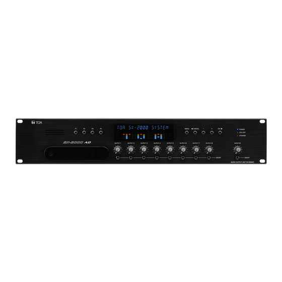
Chapter 3 SX-2000AO AUDIO OUTPUT UNIT The SX-2000AO is an audio output unit for use with the SX-2000 system. It is equipped with 8 audio outputs, 8 control inputs, and 8 control outputs. The SX-2000AO also features an emergency audio input and a 24 V emergency cutoff input* which permits the SX-2000AO to be used in conjunction with an emergency broadcast system. -
Page 24: Nomenclature And Functions Front
Chapter 3: SX-2000AO AUDIO OUTPUT UNIT 1. NOMENCLATURE AND FUNCTIONS [Front] 4 5 6 7 8 Protective cover Inside of the protective cover 1. Monitor Speaker 4. Menu Key [MENU] Allows any output channel to be monitored. Pressing this key displays the fluorescent display's menu screen. - Page 25 Chapter 3: SX-2000AO AUDIO OUTPUT UNIT 10. CPU OFF Indicator [CPU OFF] (Red) 18. ID Switch [ID NUMBER] Lights when the CPU turns off 5-7). Sets the SX-2000AO's device number. (See the separate Installation Manual.) 11. Standby Indicator [STANDBY] (Green) Flashes when the fluorescent display is in light 19.
-
Page 26: Fluorescent Display
Chapter 3: SX-2000AO AUDIO OUTPUT UNIT [Fluorescent Display] KEYLOCK FAULT EMERGENCY FADER –10 –10 –20 –20 –30 –30 LEVEL LEVEL –40 –40 22 23 24 25 26 32 33 34 21. Text Display Area enabled, this indicator flashes if the input Displays the menu screen information when the receives an emergency signal. -
Page 27: Key Lock Settings And Cancellation
Chapter 3: SX-2000AO AUDIO OUTPUT UNIT 2. KEY LOCK SETTINGS AND CANCELLATION (DIP Switch 1 Operation) It is possible to disable the output volume controls, output ON/OFF keys, monitor volume control, and monitor ON/OFF key in order to prevent mistaken operation. The output volume level set while the key lock function is used takes effect after the key lock has been released. -
Page 28: Operating The Menu Screen
Chapter 3: SX-2000AO AUDIO OUTPUT UNIT 3. OPERATING THE MENU SCREEN Setting values can be confirmed or changed from the SX-2000AO's front panel. 3.1. Menu Screen Operation Keys Fluorescent display P A N E L V O L U M E This mark is displayed when a display has sub-menus available. -
Page 29: Menu Screen Hierarchical Chart
Chapter 3: SX-2000AO AUDIO OUTPUT UNIT 3.2. Menu Screen Hierarchical Chart Default Display —1 6 V E R 1 0 0 Note Pressing the Menu key when any menu MENU screen is displayed returns the screen to MENU the default display. OK / Information Display Error Display... -
Page 30: Explanations Of Menu Screen Items
Chapter 3: SX-2000AO AUDIO OUTPUT UNIT 3.3. Explanations of Menu Screen Items 3.3.1. Information Display (AO1) 1 – I N F O R M A T I O N Display screen for menu item "Information." [Error Display (AO2)] When any of the Fault indicators on the SX-2000SM's front panel is flashing, or when the Fault indicator or COM indicator on the SX-2000AO's fluorescent display is flashing, a brief error message appears in the text display area as shown below. -
Page 31: Operation Status Display (Ao3)
Chapter 3: SX-2000AO AUDIO OUTPUT UNIT 3.3.2. Operation Status Display (AO3) 2 – O P E R A T I O N S T A T U S Display screen for menu item "Operation Status." [BGM Pattern Display (AO4)] B G M P A T T E R N N o Displays the pattern number for a BGM broadcast in progress. - Page 32 Chapter 3: SX-2000AO AUDIO OUTPUT UNIT [Front Panel Volume Display (AO7), Front Panel Volume Detail Display (AO8)] OK / P A N E L V O L U M E V O L U M E – 3 0 /CANCEL Indicates the output volume level set via the front panel's volume control in the output level meter.
- Page 33 Chapter 3: SX-2000AO AUDIO OUTPUT UNIT [Bus Selection Menu Display (AO9), Bus Selection Detail Display (AO10)] Bus No. Type of broadcast OK / B U S S E L E C T S T A T U S – – /CANCEL SX-2000AI’s SX-2000AI’s...
-
Page 34: Equipment Information Display (Ao13)
Chapter 3: SX-2000AO AUDIO OUTPUT UNIT [Control Input Status Display (AO11)] C I 1 – – – – – – Displays the current control input status. "o" is displayed when the control input is on, and "–" is displayed when the control input is off. [Control Output Status Display (AO12)] C O 1 –... - Page 35 Chapter 3: SX-2000AO AUDIO OUTPUT UNIT [Sub CPU Version Display (AO17) ] S U B C P U V E R Displays the version of software related to operations and displays on the SX-2000AO's front panel. [Hardware Version Display (AO18)] H W C Displays the hardware version for each circuit board comprising the SX-2000AO unit.
-
Page 36: Chapter 4: Remote Microphone Rm-200S
Chapter 4 REMOTE MICROPHONE RM-200S REMOTE MICROPHONE EXTENSION RM-210 The RM-200S Remote Microphone features 13 function keys, 1 covered key, 1 talk key, and the indicator lamps associated with these. The function keys can be used to select broadcast zones, change or cancel BGM patterns. - Page 37 Chapter 4: REMOTE MICROPHONE RM-200S REMOTE MICROPHONE EXTENSION RM-210 1. NOMENCLATURE AND FUNCTIONS 1.1. RM-200S [Top] 1. Microphone 6. Indication Label Insert Slots Used for voice announcements. Labels can be printed using the SX-2000 Setting Software. (See the separate Setting Software 2.
- Page 38 Chapter 4: REMOTE MICROPHONE RM-200S REMOTE MICROPHONE EXTENSION RM-210 10. Talk Key 12. Broadcast Status Indicator (Orange/Green) Press this key to broadcast a voice announcement. Lights, flashes, or extinguishes depending on the If the Talk key is set to "PTT" ("press-to-talk") current operational state of the Talk key.
-
Page 39: Rm-210
Chapter 4: REMOTE MICROPHONE RM-200S REMOTE MICROPHONE EXTENSION RM-210 1.2. RM-210 [Top] 1. Indication Label Insert Slot Labels can be printed using the SX-2000 Setting Software. (See the separate Setting Software Instructions, " Printing Labels for Remote Microphones.") 2. Broadcast Status Indicators (Orange/Green) Light, flash, or extinguish depending on the current operational state of function keys. -
Page 40: Indicator Status
Chapter 4: REMOTE MICROPHONE RM-200S REMOTE MICROPHONE EXTENSION RM-210 2. INDICATOR STATUS 2.1. Indicators During Zone Selection When a zone selection (pattern or individual) function has been assigned to a function key, the 2 indicators to the left of the key indicate its zone selection and broadcast status. Note For instructions on assigning functions to function keys, see the separate Setting Software Instructions, "RM Function Key Settings."... -
Page 41: Talk Key Indicators
Chapter 4: REMOTE MICROPHONE RM-200S REMOTE MICROPHONE EXTENSION RM-210 2.2. Talk Key Indicators Talk Key Broadcast Status Indicator Microphone Indicator The meanings of the 2 indicators next to the Talk Key are as follows: Indicator Status Meaning Microphone Indicator Microphone not in use Unlit Microphone in use Lights green... -
Page 42: Chapter 5: Operation
Chapter 5 OPERATION... -
Page 43: Broadcasting
Chapter 5: OPERATION 1. BROADCASTING 1.1. Broadcasting from the SX-2000AI or SX-2000AO Function keys F1 – F4 on the front panel can be used to change or end the BGM pattern. Function key F1 – 4 Note: The figure shows the SX-2000AI. For instructions on setting functions to function keys, ee the separate Setting Software Instructions, "Control Input Settings."... - Page 44 Chapter 5: OPERATION 1.2. Broadcasting from the RM-200S and RM-210 The function keys can be used to make microphone announcements and to change or end BGM broadcasts. For instructions on setting functions to function keys, see the separate Setting Software Instructions, "RM Function Key Settings."...
-
Page 45: Example Of Broadcasting To The Selected (Pattern-Designated) Zone
Chapter 5: OPERATION 1.2.1. Example of broadcasting to the selected (pattern-designated) zone Step 1. Press function key R1 (zones 1, 2 and 3). Broadcast status indicator All of the designated zones are selected, and the Zone selection indicator zone selection indicator next to function key R1 lights green. -
Page 46: Example Of Broadcasting To The Selected (Individual) Zone
Chapter 5: OPERATION 1.2.2. Example of broadcasting to the selected (individual) zone Step 1. Press function key R2 (zone 1) and function key Broadcast status indicator R3 (zone 2). Zone selection indicator Zones 1 and 2 are selected, and their zone selection indicators light green. -
Page 47: Example Of Bgm Broadcasting
Chapter 5: OPERATION 1.2.3. Example of BGM broadcasting Following is the operation example in the case where BGM broadcast is made by the BGM pattern 1 in the morning and changed to the BGM pattern 2 in the afternoon, and then ended. Broadcast status indicator Step 1. -
Page 48: Making Urgency All-Zone Calls (When Placing The Cpu In An "Off" Condition)
Chapter 5: OPERATION 1.2.4. Making urgency all-zone calls (when placing the CPU in an "off" condition) If normal broadcasts cannot be made due to system failure or some trouble, only an all-zone call is possible in the following procedure. This is a broadcast made by bypassing the CPU* that normally operates in the SX-2000 system. -
Page 49: Adjusting Input/Output Volume
Chapter 5: OPERATION 2. ADJUSTING INPUT/OUTPUT VOLUME It is possible to adjust the volume for each input channel via the front panel of the SX-2000AI. It is also possible to adjust the volume for each output channel via the front panel of the SX-2000AO. The adjustment method is the same for both. -
Page 50: Monitoring Input/Output Channels
Chapter 5: OPERATION 3. MONITORING INPUT/OUTPUT CHANNELS The SX-2000AI and SX-2000AO are equipped with monitor speakers on their front panels, which allow monitoring of each input (SX-2000AI) or output (SX-2000AO) channel. The monitoring method is the same for both. Input selection indicator Fluorescent display Note: The figure shows the SX-2000AI. - Page 51 200610...
Need help?
Do you have a question about the SX-2000 Series and is the answer not in the manual?
Questions and answers