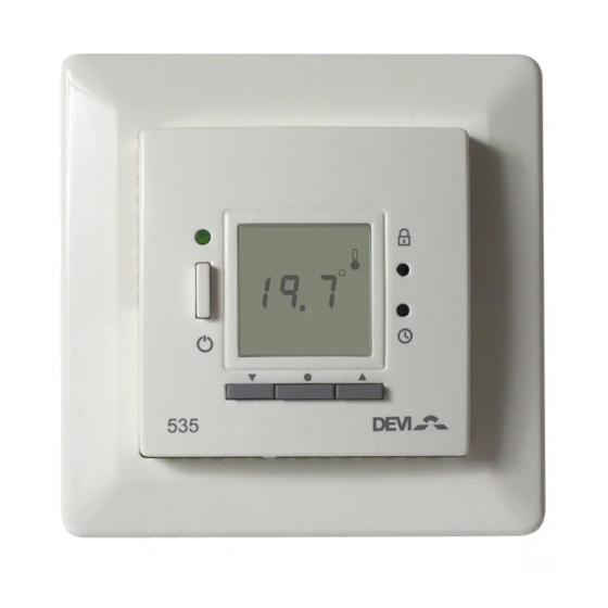
DEVI Devireg 535 Installation Manual
Hide thumbs
Also See for Devireg 535:
- User manual (24 pages) ,
- Installation manual (20 pages) ,
- Quick manual (4 pages)

Related Manuals for DEVI Devireg 535


Summary of Contents for DEVI Devireg 535
- Page 1 Devireg Installation manual Warning! This manual is only to be used by a professional installer to install and set up the thermostat properly. It is not intended for the end-user!
- Page 2 Congratulations with… ... your DEVI floor heating system Your property has been installed with a DEVI electric floor heating system. DEVI is Europe’s leading floor heating manu- facturer, with over 45 years experience. We are confident that you will be satisfied with your new system.
-
Page 3: Table Of Contents
Disposal Instruction........25 The DEVI Guarantee ....... 26... -
Page 4: Install & Configure The Thermostat
Install & configure the thermostat Placement of Devireg When Devireg 535 is used as a room sensor, installation height should typically be between 80-150 cm. In wet rooms it should be installed on an even surface, according to local building regula- tions. -
Page 5: Installation Of Devireg
Installation and connection Installation of Devireg 1. To remove the front cover, gently press the release tabs under the bottom of the thermostat with a screwdriver. Then remove the front. Removing the front cover and pushing the installation button, is not intended to be done by anyone else but a qualified installer! 2. - Page 6 Be aware that without a floor sensor, the temperature control can be less accurate, and overheating of the floor is of higher risk. DEVI recommends that a floor sensor is always installed. When the thermostat is used to control a floor heating...
- Page 7 Configuration - sensor Selection of sensor type Power on the thermostat. With the front off, with a small screw- driver, pencil, or needle press the installation button. Select the sensors to be used for the heating system: Devireg 535 is able to use two sensors: - a built-in room sensor - an external sensor to be placed...
- Page 8 Configuration - Max. floor temp. Maximum floor temperature. When selecting either floor sensor or floor and room sensors, next screen is maximum floor temperature. Default setting is 35°C. To change this setting, press • and ▲▼ use the arrow buttons to select your choice.
- Page 9 Configuration - Scale Scale If you select Devireg 535 to only use a floor sensor, mode , you have to select the display type. The choice is either numerical scale 1-6 or Celcius scale 5° to 45°. Default is Celcius scale. When select- ing Celcius, the display will show the actual temperature at the floor sensor.
-
Page 10: User's Guide To Devireg
User’s guide to Devireg Devireg 535 Introduction Devireg 535 is an electronic timer temperature controller, specially designed for floor heating systems. The Devireg 535, once set, automatically adjusts the heating to meet your comfort levels, regardless of changing weather conditions by measuring the floor temperature and combining it with the air temperature. -
Page 11: Int
Increase / decrease temperature The display indicates: Childproof Weekdays Frost protection Actual Settings temperature is displayed Room Floor temperature temperature Day rhythm periods Maximum / Minimum and comfort / econo- my temperature Increase / decrease preferred temperature. ▲▼ Use the arrow buttons to either increase or decrease the temperature. -
Page 12: Using The Timer Function
Timer function Using the timer function The thermostat has a built-in timer function. A status bar in the bottom of the display gives an overview of timer status. The day is divided into 4 time periods analogous to the typical day pro- gramming pattern: - Morning - Day... - Page 13 The 4 programs 4 different programs can be selected Program 1 Manual mode. The temperature is main- tained constantly 24 hours all week. Program 2 The temperature is lowered to economy temperature during the day and night period all week. P2 is a day program for e.g.
- Page 14 Factory settings The factory setting of the timer is: Floor Room Floor and sensor only sensor only Room sensor Temperature: Comfort 25°C 21°C 21°C Economy 5°C 17°C 17°C Periods – Day rhythm: Morning 06:00-08:00 08:00-16:00 Evening 16:00-22:30 Night 22:30-06:00 You can use the above as it is, or you can change the settings to match your day pattern.
- Page 15 Changing timer program During the timer programs, P2, P3, and P4, the flashing indicates the actual time period. In program 4 the actual day is also shown. ▲▼ Using the arrow buttons in timer mode, is somewhat different from manual mode. If you increase/decrease the temperature in a savings period this change only...
-
Page 16: Settings
Settings overview Settings All settings are under the settings menu. Here you set the following: - Time - Weekday - Timer periods configuration (Morning, day, evening and night) - Comfort temperature - Savings temperature - Min. floor temperature limit (Only when combination of room and floor sensor is installed). -
Page 17: Setting The Time
Changing the settings You enter the settings by pressing pinhole with a small screw driver, pencil, or needle, the display now changes from temperature to time display. ▲▼ By using the arrow buttons move one way or the other in the menu. -
Page 18: Setting The Timer Periods
Changing the settings Setting the timer periods When programming the starting times of the 4 periods keep in mind that the thermostat will start heating/stop heating at the given time. Therefore some periods should start and end before, to compensate for the time it takes to heat up or down. -
Page 19: Setting The Comfort Temperature
Changing the settings Setting the comfort temperature By pressing the • the preset comfort tempera- ture starts flashing. You change it with the arrow ▲▼ buttons Press the • to accept Setting the savings temperature By pressing the • the preset savings temperature starts flashing. -
Page 20: Special Features
Special features Childproof mode You disable all buttons in child proof mode by pressing the pinhole button below with a small screw driver, pencil, or needle. A lock now appears in the display and all other buttons are locked now. To unlock press the lock symbol again Frost protection mode To set the thermostat in frost protec-... -
Page 21: Off Mode
Special features OFF mode To set the thermostat in OFF mode, ▼ you hold down until you reach 5.0°. ▼ Now press again twice to verify that you are not just changing the comfort or economy temperature, depend- ing on the mode or timer period the thermostat is in. -
Page 22: Switching Displayed Temperature
Special features / Trouble shooting Switching displayed temperature Depending on what mode the thermostat is installed as (floor, or a combination of floor and room) you can change which temperature is displayed. If installed as a floor sensor system only, you can change the displayed temperature from floor sensor temperature to room sensor tempera- ture, if you wish to use the thermostat as a... -
Page 23: Trouble Shooting
Trouble shooting E4 flashing in display: Error code 4 – The thermostat has overheated and has switched off Let the thermostat cool for period. Then switch the thermostat off and on. E5 or E6 flashing in display: Error code 5 - Floor sensor short circuited Error code 6 - Floor sensor disconnected. -
Page 24: Technical Specifications
Technical specifications Operation voltage 180-250 VAC, 50/60 Hz Standby power Max. 0.30 W consumption Relay: • Resistive load 230V ~ 15A / 3450W • Inductive load cos φ= 0.3 Max. 4A Sensing unit NTC 15 kOhm at 25°C Sensing values: •... -
Page 25: Disposal Instruction
Disposal Instruction All electric or electronic equipment and enclosed batteries containing materials, components and substances that can be harmful to people’s healthiness and to the environment, if the waste is not handled correctly. All electric or electronic equipment and batteries is marked with the below crossed sign of a dustbin or garbage can. - Page 26 All work will be invoiced in full if DEVI is required to inspect or repair faults that have arisen as a result of any of the above.
-
Page 27: The Devi Tm Guarantee
2 YEAR WARRANTY Warranty Certificate The DEVI Guarantee is granted to: Name: Address: City: Country: Telephone: Attention: The Warranty Certificate must be completed correctly for the Warranty to be valid. Please read the Warranty conditions on the previous page. Type of thermostat:... - Page 28 Article No.: 08095880 Version - 01.01 DEVI A/S Ulvehavevej 61 DK-7100 Vejle Tel: +45 74 88 85 00 Fax: +45 74 88 85 01 www.devi.com...
Need help?
Do you have a question about the Devireg 535 and is the answer not in the manual?
Questions and answers