Advertisement
Table of Contents
�
Auto Meter Products Inc.
413 West Elm Street
Sycamore, IL 60178
SB-5
2
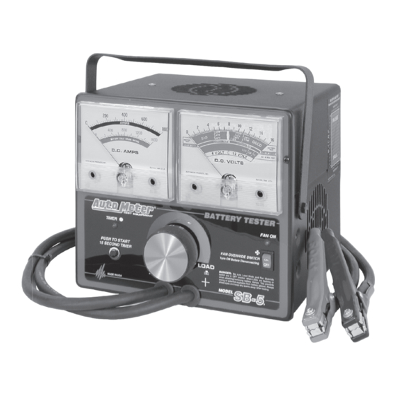
Battery Load Tester
T est Equipment
Toll Free (866) 883-TEST (8378)
Fax (815)895-6786
Instruction Manual
www.autometer.com
Simplified Check Program for Charging Systems
The SB-5
is a variable load battery tester that provides a simplified check
2650-791X-10rH
2
for alternator output and starter draw and circuit test.
24
Advertisement
Table of Contents

Subscribe to Our Youtube Channel
Related Manuals for Auto Meter SB-52


Summary of Contents for Auto Meter SB-52
- Page 1 � Auto Meter Products Inc. 413 West Elm Street Sycamore, IL 60178 SB-5 Battery Load Tester T est Equipment Toll Free (866) 883-TEST (8378) Fax (815)895-6786 Instruction Manual www.autometer.com Simplified Check Program for Charging Systems The SB-5 is a variable load battery tester that provides a simplified check 2650-791X-10rH for alternator output and starter draw and circuit test.
-
Page 2: Equipment Needed
Whenever a component fails, the whole system should be checked to by Auto Meter to affect the repair or replacement of insure that the failure was not caused by another part of the system. -
Page 3: Table Of Contents
TABLE OF CONTENTS CLAMP INSPECTION and MAINTANENCE IMPORTANT: Both jaws of each clamp must firmly engage terminals. Equipment Needed ----------------------------------------------------2 The copper jaw contains CHECK OFTEN FOR LOOSE JAWS Specifications -----------------------------------------------------------3 the smaller gauge wire that OR DAMAGED INTERNAL PLASTIC Safety ---------------------------------------------------------------------4 reads the voltage and the SHOULDER INSULATORS... -
Page 4: Safety
Carefully read all operating instructions before using the tester Wear eye protection when working In the event your tester needs to be returned to Auto Meter for service, around batteries. it must be properly packaged and protected to avoid damage during Be sure each test is completed before shipment. -
Page 5: Battery Inspection And Visual Check
BATTERY INSPECTION SERVICE INFORMATION Warranty claims to Auto Meter must be transportation prepaid and Valid automotive electrical system testing depends on all the components accompanied by dated proof of purchase. This warranty applies only to being in good operating condition. In addition, the battery MUST have the original purchaser and is non-transferable. -
Page 6: Preliminary Notes
PRELIMINARY NOTES ALTERNATOR TESTS 1. MOISTURE If tester has not been used for a period of time, moisture may have condensed BLACK between carbon pile discs. This will cause the tester to steam a little during first or second load application. This is normal and is not a malfunc tion of the tester. (Do 12 Volt System Test not confuse this with heat due to overloading the tester.) Using Two 6 Volt... -
Page 7: Controls And Functions
APPENDIX CONTROLS AND FUNCTIONS TIMER LIGHT LOAD KNOB FAN OVERIDE LIGHT MULTIPLE BATTERY SYSTEM TESTS In heavy duty applications, 6 and 12 volt charging systems are created by combining 6 and 12 Volt batteries in various combinations. For a valid test, batteries must be tested individually, and the charging system must be tested at its rated voltage (6 or 12 Volts). -
Page 8: Battery State Of Charge
BATTERY STATE OF CHARGE APPENDIX The battery must have an adequate state of charge before a valid battery load test can be performed. The state of charge can be measured with BATTERY CHARGING GUIDE a hydrometer (see Appendix A page 16), or checked by the “state of charge”... -
Page 9: Battery Load Test
APPENDIX BATTERY LOAD TEST 1. Turn load knob to apply a load equal to 1/2 the Cold Crank rating or 3 HYDROMETER METHOD times the Amp-Hour rating for 15 seconds. 2. Hold proper load for 15 seconds, observe the voltage reading, and Check the electrolyte specific gravity with a then immediately decrease the load until the fan stops and the hydrometer. -
Page 10: Starter Draw Test
STARTER DRAW TEST 6. To check the ground circuit, con nect the RED clamp directly to the starter casing (this may require chipping paint to make a good con- For proper starter functioning, it is important that all related connections nection), and the BLACK clamp to the battery negative terminal as are clean and tight, and that the cable and its insulation are in good shown in example below. - Page 11 STARTER CIRCUIT TEST STARTER DRAW TEST CONT. Example: Disable ignition as indicated in the Starter-Draw Test on page 10. 1. With ignition disabled crank vehicle and observe lowest volt reading. For this example, we’ll say it reads 11 volts. 1. Connect the tester as shown below. A with the RED clamp to battery pos itive and the BLACK clamp to the terminal on the starter, which is 2.
-
Page 12: Alternator Test
ALTERNATOR TEST continually because his battery keeps running down, but all battery and alternator tests pass. To charge a battery, the alternator must produce a voltage higher than the battery voltage to cause current to flow into it. Therefore, the voltage must rise to the “OK”...
Need help?
Do you have a question about the SB-52 and is the answer not in the manual?
Questions and answers