
Related Manuals for Calypso CA-500

Summary of Contents for Calypso CA-500
- Page 1 CA- 5 0 0 / 1 0 0 0 UDIO MPLIFIERS CA- 1 0 5 0 944 O Keefe Road Hudson, WI 54016 (Tel) 715-381-9646 (Fax) 715-381-9647 www.calypsocontrol.com sales@calypsocontrol.com support@calypsocontrol.com...
-
Page 2: Table Of Contents
Table of Contents CA-500 / CA-1000 / CA-1050 OVERVIEW .........................3 ..........................4 ROGRAM MODE VS UN MODE ............................4 IRING VERYTHING CA-C ..........................7 SING ONFIG OFTWARE IR AND SERIAL CONTROL.............................11 IR C ............................11 OMMAND ROTOCOL ..........................13 ERIAL OMMAND ROTOCOL TECHNICAL SPECIFICATIONS..........................15 WARRANTY................................16... -
Page 3: Ca-500 / Ca-1000 / Ca-1050 Overview
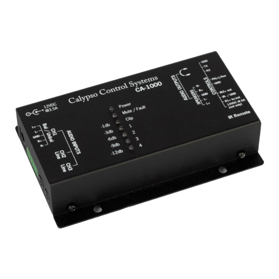
4 ohm and 8 ohm speakers, while providing full IR and Serial control. The CA-500 delivers a single balanced or unbalanced input and stereo output, while the CA-1000 offers three stereo and one mono input, with an on-board mixer for defining presets, digital gain control and automated ducking when microphone input is detected. -
Page 4: Program Mode Vs. Run Mode
Program mode vs. Run mode CA Series products have two (2) basic modes of operation: Program Mode allows general configuration of the device plus IR/Serial Trigger. Run Mode allows IR and SERIAL triggers to be recognized and decoded. The device MUST BE IN PROGRAM MODE in order for it to communicate with CA-Config software. - Page 5 1.2.2 Serial Programming/Control Cable Solder wires to pins 2, 3 and 5 of a female, 9-pin RS-232 connector Connect the wire on pin 2 (Rx) to pin 2 (Tx) of a 3-pin screw-down terminal block Connect the wire on pin 3 (Tx) to pin 1 (Rx) of a 3-pin screw-down terminal block Connect the wire on pin 5 (Gnd) to pin 3 (Gnd) of a 3-pin screw-down terminal block Plug the terminal block into the 3 pin slot on the right side of the unit and plug the DB9 connector into your computer s serial port...
- Page 6 Headphones may be plugged into the unit using the 1/8 inch mini jack located on the right side. Note that the headphone output remains active even when the amplifier output is muted on the CA-500 and CA-1000. Controller Controller CA-1000...
-
Page 7: Using Ca-Config Software
Using CA-Config Software Once the unit is wired and powered up, CA Series configuration is managed entirely by CA- Config software, which is provided on a CD with the unit. CA-Config software must be installed on the PC connected to the CA-1000 unit via the serial programming cable. After launching the software, select the appropriate serial port from the pull-down;... - Page 8 1.3.1 Input Channel Settings The CA-500 CA-Config interface will provide access to Channel 1 In only, whereas all channels will be active for CA-1000 and CA-1050 products. For each active channel, the column of push buttons provide the following functions:...
- Page 9 In multi-channel audio applications, microphones are often treated as a special input device, capable of triggering automated ducking , where the volume of other inputs automatically drop to preset levels, allowing microphone audio to be the dominant source. Accordingly, when a Mic On button is selected the Level setting for the active microphone channel is changed to a Threshold setting, which is the microphone gain threshold at which automated ducking of other channels initiates.
- Page 10 6. Tone Off toggle to turn a 900Hz test tone on and off. The goal is to provide an output signal for testing speaker connections. 7. CIRT 2 Settings assign a specific 4-char CIRT (Calypso IR Trigger) code to specific CA Series functions. Use the pulldown menu to select a specific function, type in a 4-char CIRT code and click the Assign button to associate the function with the code.
-
Page 11: Ir And Serial Control
The CA Series of products are designed to be controlled by external devices that are capable of transmitting IR or serial commands. For example, one could steer IR commands from a Calypso CW-1000 button panel to a CA-1000 IR input, and use the buttons to control audio channel selection and volume. - Page 12 2.1.2 CIRT2 Codes User Defined When necessary, you may configure the CA device to respond to ANY valid CIRT code, which amounts to creating your own CIRT2 library. For example, the Calypso CB-1000 wall mount button panel contains the following built-in CIRT codes.
-
Page 13: Serial Command Protocol
Serial Command Protocol The CA Series of products supports a fixed library of Serial commands, which can be transmitted directly to the RS-232 port on the unit, which is also for CA-Config communications. Note that each command must end with a carriage return (HEX = 0D). Command Description #ACHx... - Page 14 Command Description #AVAv Absolute volume setting, range 1-32 (-2db) 1 thru 32 Command Description Return current volume setting #AVA? Command Description Mute and un-mute output #AVMx 0 = mute 1 = un-mute Command Description #AVM Toggle mute state Command Description Return current mute setting #AVM? Page 14...
-
Page 15: Technical Specifications
Technical Specifications Audio Inputs Audio Outputs CA-500 Connectors/Channels (1) 5-pin 3.81 Terminal Block Header (CH1) (Line Out) balanced/unbalanced Stereo Connector CA-1000 / CA-1050 Connectors/Channels (1) 5-pin 3.81 Terminal Block Header (CH1) 5-pin 3.81mm Terminal Block Header balanced/unbalanced Stereo Max output (unbalanced) +2.0 dBV (1.26Vrms) -
Page 16: Warranty
This warranty is applicable to product sold or distributed to customer by an authorized Calypso Control Systems Dealer, OEM, Value Added Reseller or sold directly to the end user by Calypso Control Systems, LLC. This warranty becomes effective from the moment the end user completes purchase and receives product. - Page 17 (2) misuse, theft, vandalism, fire, water, or other peril; (3) alterations of or additions to the System or any element thereof performed by personnel not certified by Calypso Control Systems to perform such alterations and additions or (4) the Customer s failure to operate the product in conformance with Calypso Control Systems published operating parameters, including environmental specifications.
Need help?
Do you have a question about the CA-500 and is the answer not in the manual?
Questions and answers