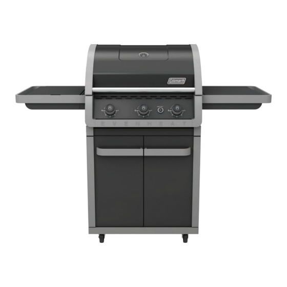
Coleman EVEN HEAT Assembly Manual
With 3 burners
Hide thumbs
Also See for EVEN HEAT:
- Assembly manual (14 pages) ,
- Assembly manual (32 pages) ,
- Assembly manual (32 pages)
Table of Contents
Advertisement
Quick Links
See also:
Assembly Manual
DURABILITY • POWER • PERFORMANCE
EVE N HE AT ™
bArb Ec u E
3
wiTH
burNErs
Assembly MANuAL
85-3068-0 (G52227) Propane
85-3069-8 (G52228) Natural Gas
LIMITED 5-YEAR WARRANTY
Read and save manual for future reference.
Assemble your grill immediately. Missing or damaged parts
should be claimed within 30 days of purchase.
For product inquiries, parts, warranty and troubleshooting support,
please call 1-800-275-4617.
www.colemanbbqs.com
Manual Revision #: 07282014 AT
Advertisement
Table of Contents

Related Manuals for Coleman EVEN HEAT


Summary of Contents for Coleman EVEN HEAT
- Page 1 DURABILITY • POWER • PERFORMANCE EVE N HE AT ™ bArb Ec u E wiTH burNErs AssEMbLY MANuAL 85-3068-0 (G52227) Propane 85-3069-8 (G52228) Natural Gas LIMITED 5-YEAR WARRANTY Read and save manual for future reference. Assemble your grill immediately. Missing or damaged parts should be claimed within 30 days of purchase.
- Page 2 H E A V Y A R T I C L E N E E D S 2 T O L I F T THIS MANUAL MUST REMAIN WITH THE PRODUCT AT ALL TIMES To ORDER non-warranty replacement parts or accessories, or to register your warranty, please visit us on the web at www.colemanbbqs.com CAUTION...
- Page 3 HArDwArE PAcK No. Description Part Number Qty. TOOLS NEEDED FOR ASSEMBLY ¼"-20UNCX38 Screw 20120-13038-250 • #2 Phillips screwdriver (long and short) ¼"-20UNCX16 Screw 20120-13016-250 φ7 Lock Washer 41400-07000-250 • ¼” Slotted screwdriver (long and short) φ7 Washer 40300-07000-250 • Adjustable wrench 1/4”-20UNC Nut 30220-13000-250 •...
- Page 4 Burner box assembly G522-M300-01 Right side shelf G522-C200-01 Even Heat™ burners G522-B600-01 Side burner control knob G522-C700-01 (#13) Carryover assembly G522-0071-01 Even Heat™ heat distribution G353-0034-01 plate Left side panel G522-F600-01 Cooking grate G522-0097-01 Right side panel G522-B900-01 Warming rack G522-00D4-01...
- Page 5 EXPLODED DiAGrAM (PrOPANE) FOr 85-3068-0 (G52227) Extras Assembly Safe Use Manual & Care Hardware Manual Pack...
- Page 6 Burner box assembly G522-M300-01 Right side shelf G522-C200-01 Even Heat™ burners G522-B600-01 Side burner control knob G522-C700-01 (#13) Carryover assembly G522-0071-01 Even Heat™ heat distribution G353-0034-01 plate Left side panel G522-F600-01 Cooking grate G522-0097-01 Right side panel G522-B900-01 Warming rack G522-00D4-01...
- Page 7 EXPLODED DiAGrAM (natural gas) FOr 85-3069-8 (G52228) Extras Assembly Safe Use Hardware Manual & Care Pack Manual...
- Page 8 AssEMbL Y iNsTrucTiONs a. Separate the 2 different types of castors: 2 locking castors (EG) and 2 regular castors (EH). NOTE: Regular castors (EH) need to be assembled to the front of the bottom shelf (EF), and locking castors (EG) need to be assembled to the back of the bottom shelf (EF), as shown in image A.
- Page 9 AssEMbL Y iNsTrucTiONs Ensure that the locking castors (EG) are firmly locked in the “ON” position before continuing. Assemble the left side panel (EA) and the right side panel (EB), to the bottom shelf (EF). YOU WILL NEED: Front view Close up Attach the front brace (CI) to the left and right cart side panels (EA and EB).
- Page 10 AssEMbL Y iNsTrucTiONs THIS STEP REQUIRES 3 PEOPLE. DO NOT ATTEMPT ALONE. EXTREMELY HEAVY. Position the top lid assembly and burner box assembly (A & B) onto the cart assembly (C), as shown. Front view Attach the upper back panel (CL) to both the left and right side panels (EA &...
- Page 11 AssEMbL Y iNsTrucTiONs a. Assemble the left and right tracks (CO and CN) for the Quick Clean™ grease tray (CJ), as shown in figure A-C. Back view b. Both the left and right tracks (CO and CN) should be inserted into the two clips located on the front brace (CI), as shown in figure B.
- Page 12 AssEMbL Y iNsTrucTiONs TIP: Do not tighten until all hardware is in place. a. Mount the right side shelf (DG) onto the two support brackets, located on the right, upper side panel of the burner box (BA). Front view b. Assemble the front of the right side shelf (DG) to the control panel (CH), as shown in figure B.
- Page 13 AssEMbL Y iNsTrucTiONs TIP: Do not tighten until all hardware is in place. a. Mount the left side burner side shelf (DA) onto the two support brackets, located on the left, upper side panel of the burner box (BA). Front view b.
- Page 14 AssEMbL Y iNsTrucTiONs a. Remove the hardware that is pre-assembled to the side burner valve (CC). Feed the side burner valve (CC) through the bottom of the left side burner side shelf (DA), and re-attach the hardware, as shown. Front, left side view b.
- Page 15 AssEMbL Y iNsTrucTiONs e. Using the wing nut (#14), assemble the side burner (DC) to the side burner drip pan (DB), as shown. YOU WILL NEED: f. Locate the side burner electrode wire (DD) and insert into the base of the side burner electrode (DC), as shown in figure E.
- Page 16 AssEMbL Y iNsTrucTiONs ELECTRONIC IGNITION: ELECTRODE ASSEMBLY TIP: The Electrode Set, main burner (CF) and the Electrode wire, side burner (DD), can be found attached to the control panel (CH) heat shield, as shown in figure C. Control panel, right side d.
- Page 17 AssEMbL Y iNsTrucTiONs a. Assemble the heat shield (CM) to the bottom of the front brace (CI) as shown in figure A. YOU WILL NEED: Front view b. Assemble the back of the heatshield (CM) to the upper back panel (CL), as shown in figure B.
- Page 18 AssEMbL Y iNsTrucTiONs Assemble the door support rail (CP) to the left and right upper side panels (EA and EB), as shown. WARNING: This part may have sharp edges. Wear protective gloves when assembling. YOU WILL NEED: Front, left side view Close up, front view Assemble the door handle (EE) to the left and right door assembly (EC and ED)
- Page 19 AssEMbL Y iNsTrucTiONs PROPANE MODEL SHOWN a. Assemble the right door assembly (ED), to the bottom shelf (EF) by inserting the fixed pin (bottom of door) into the hole provided (figure B). Bottom of door b. Assemble the top of the door assembly (ED) to the door support rail (CP), by pressing in the door support pin and aligning with the hole located...
- Page 20 AssEMbL Y iNsTrucTiONs d. Position the Even Heat™ heat distribution plates (BD) into the burner box (BA) as shown. Close up, front view Close up, back view a. Position the Quick Clean grease tray (CJ) onto the right and left tracks (CN and CO), as shown.
- Page 21 AssEMbL Y iNsTrucTiONs a. Assemble the warming rack (BF) by inserting the three fixed pins into the three holes provided on the burner box back panel (BA), as shown in figure A. b. Place the cooking grates (BE) into the burner box (BA), as shown in figure A.
- Page 22 AssEMbL Y iNsTrucTiONs FOR NATURAL GAS MODEL ONLY. Attach the natural gas hose (CB) to the side burner valve (CC), as shown. ATTENTION: In order to complete installation of your Natural Gas BBQ a 1/2” or 3/8” adapter may be required to connect your BBQ’s Natural gas hose to your home gas supply.
- Page 23 ADDiTiONAL wArNiNGs You have now completed the Assembly of your COLEMAN® EVEN HEAT™ BARBECUE. NEXT STEPS: 1. Position your BARBECUE 2. Read SAFE USE CARE MANUAL 3. Perform Grill Safety Check-list WARNING HOT SURFACES: WARNING: FOR YOUR FAMILIES SAFETY, DO NOT ATTEMPT TO LIGHT...
- Page 24 Join the conversation facebook.com/colemangrills twitter.com/colemangrills Manufactured by Winners Products Engineering Ltd. Coleman are registered trademarks of ® The Coleman Company, Inc. used under license. ©2015 The Coleman Company, Inc. www.colemanbbqs.com...
Need help?
Do you have a question about the EVEN HEAT and is the answer not in the manual?
Questions and answers