Advertisement
Quick Links
This Owner's Manual is provided and hosted by Appliance Factory Parts.
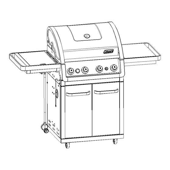
Coleman 85-3029-4/g52208
Owner's Manual
Shop genuine replacement parts for Coleman
85-3029-4/g52208
Find Your Coleman Grill Parts - Select From 255 Models
-------- Manual continues below --------
Advertisement

Related Manuals for Coleman EVEN HEAT 85-3028-6


Summary of Contents for Coleman EVEN HEAT 85-3028-6
- Page 1 This Owner's Manual is provided and hosted by Appliance Factory Parts. Coleman 85-3029-4/g52208 Owner's Manual Shop genuine replacement parts for Coleman 85-3029-4/g52208 Find Your Coleman Grill Parts - Select From 255 Models -------- Manual continues below --------...
-
Page 2: Assembly Manual
DURABILITY • POWER • PERFORMANCE EV EN HEA T™ BA RB E CUE WITH BURNERS ASSEMBLY MANUAL 85-3028-6 (G52207) Propane 85-3029-4 (G52208) Natural Gas LIMITED 5-YEAR WARRANTY Read and save manual for future reference. Assemble your grill immediately. Missing or damaged parts should be claimed within 30 days of purchase. - Page 3 H E A V Y A R T I C L E N E E D S 2 T O L I F T THIS MANUAL MUST REMAIN WITH THE PRODUCT AT ALL TIMES To ORDER non-warranty replacement parts or accessories, or to register your warranty, please visit us on the web at www.colemanbbqs.com CAUTION...
- Page 4 G522-1000-01 Carryover assembly G522-0087-01 Side burner control knob G522-2800-01 Even Heat™ heat distribution G522-0072-01 plate Left side panel G522-0300-01 Coleman stainless steel G522-0024-01 Right side panel G522-0400-01 cooking grates Left door assembly G522-8100-01 Warming rack G515-0058-01 Right door assembly G522-9100-01...
- Page 5 G522-1000-01 Carryover assembly G522-0087-01 Side burner control knob G522-2800-01 Even Heat™ heat distribution G522-0072-01 plate Left side panel G522-0300-01 Coleman stainless steel G522-0024-01 Right side panel G522-0400-01 cooking grates Left door assembly G522-8100-01 Warming rack G515-0058-01 Right door assembly G522-9100-01...
- Page 6 ASSEMBLY INSTRUCTIONS a. Separate the 2 different types of castors: 2 locking castors (EG) and 2 regular castors (EH). b. Insert the U Pin (#15) into one of the regular castors (EH), as shown in image B. Attach the regular castor (EH) to the front of the bottom shelf (EF), and use the U Pin (#15) to secure Close up...
- Page 7 ASSEMBLY INSTRUCTIONS THIS STEP REQUIRES 3 PEOPLE. DO NOT ATTEMPT ALONE. EXTREMELY HEAVY. Position the top lid assembly and burner box assembly (A & B) onto the cart assembly (C), as shown. Front view Attach the upper back panel (CL) to both the left and right side panels (EA &...
- Page 8 ASSEMBLY INSTRUCTIONS c. Assemble the Quick Check tank support bracket (EL3) to the left side panel(EA), as shown in Figure E and F. YOU WILL NEED: Left side panel, Inside View Left side, outside view d. Final image reflects the proper assembly of the Quick Check fuel gauge assembly (EL).
- Page 9 ASSEMBLY INSTRUCTIONS TIP: Do not tighten until all hardware is in place. a. Mount the right side shelf (DG) onto the two support brackets, located on the right, upper side panel of the burner box (BA). Front view b. Assemble the front of the right side shelf (DG) to the control panel (CH), as shown in figure B.
- Page 10 ASSEMBLY INSTRUCTIONS a. Remove the hardware that is pre-assembled to the side burner valve (CC). Feed the side burner valve (CC) through the bottom of the left side burner side shelf (DA), and re-attach the hardware, as shown. b. Assemble the side burner control knob (#13) to the side burner valve (CC).
- Page 11 ASSEMBLY INSTRUCTIONS ELECTRONIC IGNITION: ELECTRODE ASSEMBLY TIP: The Electrode Set, main burner (CF) and the Electrode wire, side burner (DD), can be found attached to the control panel (CH) heat shield, as shown in figure C. Control panel, right side d.
- Page 12 ASSEMBLY INSTRUCTIONS Assemble the door support rail (CP) to the left and right upper side panels (EA and EB), as shown. WARNING: This part may have sharp edges. Wear protective gloves when assembling. YOU WILL NEED: Front, left side view Close up, front view Assemble the door handle (EE) to the left and right door assembly (EC and ED)
- Page 13 ASSEMBLY INSTRUCTIONS d. Slide the condiment baskets (EJ) into the left and right door assembly (EC and ED), as shown. Position the Even Heat heat distribution plates (BD) into the burner box (BA) as shown.
- Page 14 ASSEMBLY INSTRUCTIONS FOR PROPANE MODEL ONLY. For natural gas model, follow step 21. a. Feed the regulator (CB) through the opening on the left side panel (EA). b. Mount the 20lb propane cylinder onto the Quick Check tank support bracket (EL3), located on the inside of the left side panel (EA).
- Page 15 WWW.COLEMANBBQS.COM Manufactured by Winners Products Engineering Ltd. Coleman are registered trademarks of ® The Coleman Company, Inc. used under license. ©2010 The Coleman Company, Inc.
Need help?
Do you have a question about the EVEN HEAT 85-3028-6 and is the answer not in the manual?
Questions and answers