Fusion MS-AM504 User/Instalation Manual
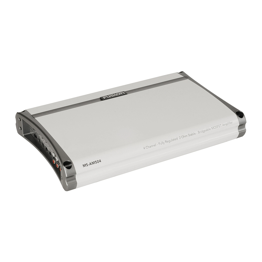
Marine amplifier
Hide thumbs
Also See for MS-AM504:
- User & installation manual (16 pages) ,
- User & installation manual (12 pages)
Advertisement
Table of Contents
- 1 Table of Contents
- 2 Feature Overview
- 3 Control Descriptions
- 4 Installation
- 5 Connections
- 6 Inputs and Gain Setup
- 7 Two Channel Installation
- 8 Three Channel Installation / Power Cable Calculator
- 9 Four Channel Installation / Trouble Shooting
- 10 Specifications
- Download this manual
See also:
Installer and User Manual
Advertisement
Table of Contents

Related Manuals for Fusion MS-AM504


Summary of Contents for Fusion MS-AM504
- Page 1 MS - A M50 4 M A R I N E A M P L I F I E R User/Installation Manual FUSIONENTERTAINMENT.COM...
-
Page 2: Table Of Contents
Contents Feature Overview ........Pg 3 Control Descriptions . -
Page 3: Feature Overview
Feature Overview • 2 Ohm Stable MOSFET Amplifier Design • Variable Bass Boost 0 - + 18dB • Variable LP and HP Electronic X-OVER @ 18dB/octave • 4 Gauge Power and Ground Connections • Nickel Plated Audio Input and Output RCA Connections •... -
Page 4: Control Descriptions
Control Descriptions 11 12 1 Power And Status LEDs: This shows if the amplifier has been correctly powered up and if any faults are pre- sent. 2 Crossover Selector: Set the appropriate mode of operation. The 3 positions available are OFF, LP and 3 Low Pass: Set the crossover switch 2 to LP when a subwoofer is connected. -
Page 5: Subsonic Filter
14 Fuses: Please ensure the correct type of fuse is fitted, as specified in this manual. PLEASE NOTE: the MS-AM504 has 2x 25A fuses. 15 Speaker Output: See channel installation diagrams in this manual for correct speaker connection. -
Page 6: Installation
FUSION dealer. Connection FUSION amplifiers are designed to work within a 10 to 16 volt DC range. Before any wires are connected, the vessel’s electrical system should be checked for correct voltage supply with the help of a voltmeter. First, check the voltage at the battery the voltmeter should read between 12 and 13.8 Volts. - Page 7 Use a fuse or circuit breaker of equal value as that found on the chassis of your FUSION amplifier. You may now connect the cable to the battery, but remember to leave the fuse out or circuit breaker off until all other cable connections are made.
-
Page 8: Inputs And Gain Setup
Inputs & Gain Setup Low Level Inputs Be extra careful with your RCA interconnects. Hiss, engine noise, and fan noise can easily be picked up through RCA cables if run incorrectly. Avoid running your RCAs near large wire looms and electric fans if possible. Run your RCA cables on the opposite side of the power cable. -
Page 9: Three Channel Installation / Power Cable Calculator
Power Cable Calculator 0-4ft 4-7ft 7-10ft 10-13ft 13-16ft 16-19ft 19-22ft 22-28ft Total Amperage 0-20 20-35 35-50 50-65 65-85 85-105 105-125 125-150 The above chart shows cable gauges to be used, if no less than a 0.5 volt drop is acceptable. If aluminium wire or tinned wire is used, the gauges should be of an even larger size to compensate. -
Page 10: Four Channel Installation / Trouble Shooting
Trouble Shooting Problem Cause Solution Fuse at battery blown or Replace with correct type and rated fuse. not installed Power LED not ‘ON Check that the ground wire, power wire and the Improper connections remote wires are connected to the correct terminal Fuse blown Replace with correct type and rated fuse. -
Page 11: Specifications
Specifications Signal to Noise >95dB Separation >60dB Input Sensitivity 300mV - 8V LP Variable Crossover 40Hz - 160Hz @ 18dB/octave HP Variable Crossover 40Hz - 600Hz @ 18dB/octave Variable Bass Boost 0 - + 18dB @ 45Hz Variable Subsonic Filter 20Hz - 55Hz @ 18dB/octave Input Impedance 20kΩ... - Page 12 FUSIONENTERTAINMENT.COM...
Need help?
Do you have a question about the MS-AM504 and is the answer not in the manual?
Questions and answers