
Related Manuals for Daewoo KOG-361Q


Summary of Contents for Daewoo KOG-361Q
- Page 1 Service Manual Microwave Oven KOG-361Q, KOG-362Q, KOG-364Q KOG-381Q, KOG-382Q, KOG-384Q KOG-388Q DAEWOO ELECTRONICS CO., LTD.
-
Page 2: Table Of Contents
PRECAUTIONS TO BE OBSERVED BEFORE AND DURING SERVICING TO AVOID POSSIBLE EXPOSURE TO EXCESSIVE MICROWAVE ENERGY (a) Do not operate or allow the oven to be operated with door open. (b) Make the following safety checks on all ovens to be serviced before activating the mag- netron or other microwave source, and make repairs as necessary : (1) Interlock operation, (2) proper door closing, (3) seal and sealing surfaces (arcing, wear, and other damage), (4) damage to or loosening of hinges, (5) evidence of dropping or abuse. -
Page 3: Proper Use And Service Precautions
CAUTION : This device is to be serviced only by properly qualified service personnel. consult the service manual for proper Service procedures to assure continued safety operation and for precautions to be taken to avoid possible exposure to excessive microwave energy. -
Page 4: Specifications
SPECIFICATIONS KOG-361Q/362Q/364Q KOG-381Q/382Q/384Q/388Q POWER SUPPLY 230V~50Hz, SINGLE PHASE WITH EARTHING MICROWAVE 1200W 1350W POWER CONSUMPTION GRILL 1050W 1050W COMBINATION 2200W 2350W MICROWAVE ENERGY OUTPUT 800W 900W MICROWAVE FREQUENCY 2450MHz OUTSIDE DIMENSIONS (W x D x H) 465 x 360 x 274 mm... -
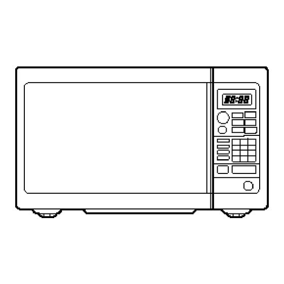
Page 5: Features Diagram
FEATURES DIAGRAM 1 Door latch–When the door is closed it will 12 Speedy cook–Touch to set the any automatically lock shut. If the door is desired reheat setting. opened while the oven is operating, the 13 Combi–Used to cook COMBI. magnetron will automatically shut off. -
Page 6: Earthing Instructions
• This appliance is supplied with cable of special type, which, if damaged, must be repaired with cable of same type. such a cable can be purchased from DAEWOO and must be installed by a Qualified Person. -
Page 7: Operation Procedure
OPERATION PROCEDURE This section includes useful information about oven operation. 1. Plug power supply cord into a 230V 50Hz power outlet. 2. After placing the food in a suitable container, open the oven door and put it on the glass tray. The glass tray must always be in place during cooking. -
Page 8: Controls
CONTROLS SETTING THE CLOCK When the oven is first plugged in, the display will flash “ : 0” and a tone will sound. If the AC power ever goes off, the display will flash “ : 0” when the power comes back on. DO THIS THIS HAPPENS... -
Page 9: Weight Defrosting
WEIGHT DEFROSTING WEIGHT DEFROST lets you easily defrost food by eliminating guesswork in determining defrosting time. The minimum weight for WEIGHT DEFROST is 200 grams. The maximum weight for WEIGHT DEFROST is 3000 grams. Follow the steps below for easy defrosting. DO THIS THIS HAPPENS... -
Page 10: Time Defrosting
TIME DEFROSTING When TIME DEFROST is selected, the automatic cycle divides the defrosting time into periods of alternating defrost and stand times by cycling on and off. DO THIS THIS HAPPENS... The WEIGHT DEFROST indica- AUTO tor lights and “0” is displayed. DEFROST And the g indicator starts blink- ing. -
Page 11: Cooking In One Stage
COOKING IN ONE STAGE DO THIS... THIS HAPPENS... The M/W indicator lights and POWER “P- ” is displayed. 1. Touch POWER pad. The display will show what you touched. This example shows power level 3. 2. Touch the number pad for the power NOTE: If steps 1 and 2 are level you want. -
Page 12: Grill Cooking
GRILL COOKING This function allows you to brown food quickly. The heating element is located in the top of the oven. There is no pre-heating the oven for grill cooking. Place food inside the oven when setting the con- trols. DO THIS... -
Page 13: Combi Cooking
COMBI COOKING This oven has combination mode which cooks food with heater and microwave at the same time. The combination mode accelerates the cooking process. DO THIS... THIS HAPPENS... The COMBI indicator lights and COMBI “ :0” is displayed. Pressing this pad repeatedly 1. -
Page 14: Auto Start
AUTO START Allows you to program cooking to start at a time you select. The food will automatically start cooking at the desired time. DO THIS... THIS HAPPENS... 1. Program the desired power level and cooking time. The AUTO START indicator CLOCK/ lights and “... -
Page 15: To Check Auto Start Time
TO CHECK AUTO START TIME Once you have correctly programmed the oven for AUTO START, the present time will appear on the display. DO THIS... THIS HAPPENS... The programmed AUTO START CLOCK/ time will appear on the display A.START for 3 seconds. 1. -
Page 16: One Touch Cooking
ONE TOUCH COOKING One touch cook allows you to cook or reheat many of your favorite foods by touching just one pad. To increase quantity, touch chosen pad until number in display is same as desired quantity to cook. (except for DINNER PLATE) DO THIS... - Page 17 * BEVERAGE * (250ml/cup) • 1 cup (mug): Touch BEVERAGE once. • 2 cups (mugs): Touch BEVERAGE twice within 1.5 seconds. • 3 cups (mugs): Touch BEVERAGEthree times within 1.5 seconds. NOTE: 1. This setting is good for restoring cooled beverage to a better drinking temperature. 2.
- Page 18 DO THIS... THIS HAPPENS... When you touch FRESH VEG- FRESH ETABLE pad, “200” is displayed. VEGETABLE After the 1.5 seconds, the dis- play changed into cooking time 1. Touch FRESH of quantity and the oven starts VEGETABLE pad. cooking. * FRESH VEGETABLE * •...
-
Page 19: Feeding Bottle
FEEDING BOTTLE This key is for feeding bottle disinfection effect. At first, detach the nipple from the bottle and pour the 30cc water into each bottle, arrange the bottle symmetrically on the glass tray and operate. DO THIS... THIS HAPPENS... When you touch FEEDING FEEDING BOTTLE pad, “2”... -
Page 20: Interlock Mechanism Functions And Adjustments
INTERLOCK MECHANISM FUNCTIONS AND ADJUSTMENTS The door lock mechanism is a device has been specially designed to completely eliminate microwave radiation when the door is opened during operation, and thus to perfectly prevent the danger resulting from the leakage of microwave. (1) Primary interlock switch When the door is closed, the hook locks the oven door. - Page 21 (2) Secondary interlock switch and interlock monitor switch When the door is closed, the hook pushes the push lever down ward, and push lever presses the button of the interlock monitor switch to bring it under “off”, condition and presses the button of the secondary interlock switch to bring it under “on”, condition.
-
Page 22: Safety Precautions For Disassembly And Repair
SAFETY PRECAUTIONS FOR DISASSEMBLY AND REPAIR – Cautions to be observed when trouble shooting. Unlike many other appliances, the microwave oven is a high-voltage, high-current equipment. It is completely safety during normal operation. However, carelessness in servicing the oven can result in an electeric shock or possible danger from a short circuit. -
Page 23: Disassembly And Assembly
DISASSEMBLY AND ASSEMBLY 1. To remove cabinet. Remove three screws (F02) on cabinet back. 2. To remove door assembly. 1) Remove two screws (F40) which secure the top hinge seoppr (F37). 2) Remove the door assembly (F00) from the top plate of cavity. 3) Reverse the above for reassembly. - Page 24 (1) Remove the gasket door (A06) from door plate (A04). (2) Remove the barrier screen inner (A05) from door plate (A04). (3) Remove the door frame (A02) from door plate (A04). (4) Remove the top hinge stopper (A03) from door plate (A04). (5) Remove the spring (A08) and the hook (A07).
- Page 25 5. To remove control panel parts. (1) Remove the screw which secur the con- trol panel, push up two snap fits and draw forward the control panel assenbly. NOTE: Do not attempt to remove switch membrane except for replacement. (2) Remove the door open lever (B05) from the control panel (B02). (3) Remove three screws (B04) which secure the P.C.B.
- Page 26 6. To remove high voltage capacitor. (1) Remove the screw (F13) which secure the grounding ring terminal of diode (F16) and capacitor holder (F14). (2) Remove the capacitor holder (F14) with capacitor (F15). (3) Reverse the above steps for reassembly. High voltage circuit wiring 7.
- Page 27 CAUTION: Never install the magnetron without the metallic gasket plate which is packed with each magnetron to prevent microwave. Whenever repair work is carried out on magnetron, check the microwave leakage. It shall not exceed 4mW/cm for a fully assembled oven with door normally closed. 8.
- Page 28 10. To remove insulator Heater assembly. (1) Remove the four HEX NUTS 1. (2) Remove the insulator Heater assembly 2. (3) Reverse the above steps for reassembly. 11. To remove Heater Part. PART NAME PART CODE Q’TY DESCRIPTION REMARK INSULATOR HEATER 3513301100 SPP T0.8 HEATER...
-
Page 29: Trouble Shooting Guide
TROUBLE SHOOTING GUIDE Following the procedures below to check if the oven is defective or not. 1. Check grounding before checking trouble. 2. Be careful of the high voltage circuit. 3. Discharge the high voltage capacitor. (see page 21) 4. When checking the continuity of switches or of the high voltage transformer, disconnect one lead wire from these parts and then check cintinuity with the AC plug removed. - Page 30 (TROUBLE 2) Digital readout display does not show programming, even if the mem- brane keyboard is programmed by touching proper pads. Cause Cause Condition Check Result Malfunction Replace Display does not Check each pad for Normal of touch control show programming continuity of the control box sub-...
- Page 31 2. Type of encoding and pad names. Fig. 8 Key Matrix The membrane keyboard consists of 27 keys whose configurations are described above and provide 11 pad terminations to be connected to the touch control circuit as Fig. 7. 3. Key check procedure. To determine if the membrane keyboard is defective or not, check the continuity of each pad (KEY) contacts with a multimeter.
- Page 32 (TROUBLE3) The oven not operate at all; Display window does not display any figures and any inputs can not be accepted. Cause Cause Condition Check Result Malfunction of Replace 15A fuse Check continuity Continuity Interlock monitor Primary blows Interlock Monitor switch Interlock Switch switch with door...
- Page 33 Cause Cause Condition Check Result Outlet has Check continuity Defective oven Replace proper of oven thermostat. Continuity voltage thermostat Fuse does not open Check continuity Open power Replace of power supply supply cord. Continuity cord. Defective touch Replace Normal control circuit Malfunction of Display do not secondary...
- Page 34 Cause Cause Condition Check Result Turn table Check continuity Open winding Replace motor, of primary wind- Conntinuity fan motor and oven lamp turn of high voltage on for a Defective touch transformer and Replace second when Normal control circuit touch control the start pad circuit is tapped...
- Page 35 (TROUBLE 6) Micrwave Output power is low . First of all, check if output power is really low following “measurement of the microwave output power” on page 35. Cause Cause Condition Check Result Customer Output Check the power Lower than Descrease in education power is low.
-
Page 36: Measurement Of The Microwave Output Power
MEASUREMENT OF THE MICROWAVE OUTPUT POWER Microwave output power can be checked by indirectly measuring the temperature rise of a certain amount of water exposed to the microwave as directed below. Proedure 1. Microwave power output measurement is made with the microwave oven supplied at rated Voltage and operated at its maximum microwave power setting with a load of 1,000±5cc of potable water. - Page 37 Procedure A) Prepare Microwave Energy Survey Meter, 600cc glass breaker, glass thermometer 100°C or 212°F. B) Pour 275cc±15cc of tap water initially at 20±5°C (68±9°F) in the 600cc beaker with an inside diam- eter of approx. 8.5 cm (3.5 in). C) Place it at the center of the tray and set it in a cavity.
-
Page 38: Wiring Diagram
WIRING DIAGRAM (GERMANY) - Page 39 WIRING DIAGRAM...
-
Page 40: Circuit Description
CIRCUIT DESCRIPTION Refer to the “WIRING DIAGRAM” on page 37. MICROWAVE COOKING TIME COOKING 1. When the food is placed inside the oven and door is closed. 1) The low voltage transformer supplies the necessary voltage to the touch control circuit when the power cord is plugged in. - Page 41 Fig. 2 The touch control circuit controls the ON-OFF time of RELAY “1” in order to vary the output power of the microwave oven from “power level 1“ to “HI (100%) power”. One complete ON and OFF cycle of the RELAY “1” is 29 seconds. The relation between indications on the control panel and the output of the microwave oven is as shown in Fig.
- Page 42 OUTPUT POWER POWER LEVEL RELAY “1” TURN ON, OFF TIME AGAINST FULL POWER 0/29 (0%) 3/29 (10%) 5/29 (17%) 8/29 (28%) 11/29 (38%) 14/29 (48%) 17/29 (59%) 20/29 (69%) 23/29 (79%) 26/29 (90%) 29/29 (100%) Fig. 3 AUTO DEFROST CYCLE When auto defrost is selected and the desired defrosting time is chosen, the automatic cycle divides the defrosting time into 5 periods of alternating defrost and stand times, by cycling on and off.
-
Page 43: Component Test Procedure
COMPONENT TEST PROCEDURE 1. High voltage is present at the high voltage terminal of the high voltage transformer during any cook- ing cycle. 2. It is neither necessary nor advisable to attempt measurement of the high voltage. 3. Before touching any oven components or wiring, always unplug the oven from its power source and discharge the capacitor (see page 21). -
Page 44: Safety Interlock Continuity Test
SAFETY INTERLOCK CONTINUITY TEST • Disconnect the oven from the power supply. • You can test continuity of safety interlocks and monitor switch by using switch tester or ohmmeter. • The switch operation is checked by the lamp on/off of resistance zero/unlimited. •... -
Page 45: Printed Circuit Board
PRINTED CIRCUIT BOARD 1. CIRCUIT CHECK PROCEDURE 1) Low Voltage Transformer (DMR-604FS) Check. The low voltage transformer is located on the P.C.B. Measuring condition: Input voltage: 230V Frequency: 50Hz Voltage LOAD NO LOAD Terminal 6–7 8–10 2.4V 2.5V NOTE 1: Secondary side voltage of the low voltage transformer changes in proportion to fluctua- tion of power source voltage. - Page 46 3) Display problems CAUSE MEASUREMENT RESULT REMEDY Poor contact between Check the voltage Fix the PIN 1 & 25 P.C.B. and display of PIN 1 & PIN 25. 2.4 VAC on the P.C.B. filament. Defective Display Refer to “The display Replace P.C.B.
- Page 47 Fig. 6 Measurement Point...
- Page 48 CHECK METHOD POINT STAGE RELAY “2” ON –24VDC RELAY “2” OFF (2) When touching “START” pad, oven lamp turns on. Fan motor and turntable rotate and cook indicator in display comes on. * Cause: RELAY “1” does not operate. CHECK METHOD POINT STAGE RELAY “1”...
- Page 49 5) When the digital clock does not operate properly. POINT WAVEFORM If clock does not keep exact time, you must check resistor R11, R17. 7) When there is not grill heat. When touching “START” pad, oven lamp turns on. Fan Motor and turntable rotate and cook indicator in display comes on. * Cause: RELAY “4”...
-
Page 50: Component Information
2. COMPONENT INFORMATION 1) Transistor 2) Diode and Zener Diode... -
Page 51: Printed Circuits Board
3. PRINTED CIRCUITS BOARD... -
Page 52: Circuit Diagram
4. P.C.B. CIRCUIT DIAGRAM... -
Page 53: Location No
5. P.C.B. LOCATION No. REF No. PART CODE PART NAME DESCRIPTION REMARK R10, 13, 18, 26 RD-AZ472J- RESISTOR 4.7 Kohm, 1/6W, 5% RD-AZ201J- RESISTOR 200 ohm, 1/6W, 5% R5, 8 RD-AZ203J- RESISTOR 20 Kohm, 1/6W, 5% RD-AZ105J- RESISTOR 1 Mohm, 1//6W, 5% R2, 4, 6, 9, 15, 20 RD-AZ102J- RESISTOR 1 Kohm, 1/6W, 5%... -
Page 54: Exploded And Parts List
EXPLODED AND PARTS LIST 1. Door Assembly KOG-36XX REF No. PART CODE PART NAME DESCRIPTION Q’TY REMARK KOG-3615OS ONLY KOG-361Q 3511706010 3511707310 DOOR ASSEMBLY KOG-3625OS ONLY KOG-362Q 3511706030 KOG-3645OS ONLY KOG-364Q 3517003000 ONLY KOG-361Q 3517003020 BARRIER-SCREEN * O PMMA ONLY KOG-362Q... -
Page 55: Control Panel Assembly
2. Control Panel Assembly KOG-36XX REF No. PART CODE PART NAME DESCRIPTION Q’TY REMARK PKCPSWSC00 KOG-361QOS ONLY KOG-361Q PKCPSWSD00 CONTROL PANEL AS KOG-362QOS ONLY KOG-362Q PKCPSWSK00 KOG-364QOS ONLY KOG-34Q 3518514600 KOG-361QOS ONLY KOG-361Q 3518515400 SWITCH MEMBRANE KOG-362QOS ONLY KOG-362Q 3518515700... - Page 57 REF No. PART CODE PART NAME DESCRIPTION Q’TY REMARK 3510801300 ONLY KOG-36XX CABINET PCM T0.6 3510801400 ONLY KOG-38XX 7S312X4081 SCREW TAPPING T1 TRS 4 x 8 SE MFZN 3516105010 KOG-381QOS ONLY KOG-38XX CAVITY WELD AS 3516104910 KOG-361QOS ONLY KOG-36XX 7S342X40B1 SCREW SPECIAL T2S TRS 4 x 12 SE MFZN 7S342X40B1...
- Page 58 REF No. PART CODE PART NAME DESCRIPTION Q’TY REMARK 5S762S10G0 SW MICRO V16-FA-63 SPNO 5S762310G0 SW MICRO V16-FA-61 2C 3P 5S762S10G0 SW MICRO V16-FA-63 SPNO 3513701300 LEVER LOCK 3513805700 LOCK POM BLACK 3513601600 LAMP BL 240V 25W T25 C7A H1 3518603700 NOISE FILTER DWLF-M...
Need help?
Do you have a question about the KOG-361Q and is the answer not in the manual?
Questions and answers