
Subscribe to Our Youtube Channel
Related Manuals for Daewoo KOG-36A5


Summary of Contents for Daewoo KOG-36A5
- Page 1 Service Manual Microwave Oven Model : KOG-36A5 DAEWOO ELECTRONICS CO., LTD. OVERSEAS SERVICE DEPT.
-
Page 2: Table Of Contents
PRECAUTIONS TO BE OBSERVED BEFORE AND DURING SERVICING TO AVOID POSSIBLE EXPOSURE TO EXCESSIVE MICROWAVE ENERGY (a) Do not operate or allow the oven to be operated with the door open. (b) Make the following safety checks on all ovens to be serviced before activating the magnetron or other microwave source, and make repairs as necessary: (1) Interlock operation, (2) proper door closing, (3) seal and sealing surfaces (arcing, wear, and other damage), (4) damage to or loosening of hinges and latches, (5) evidence of dropping or abuse. -
Page 3: Proper Use And Service Precautions
CAUTION : This Device is to be Serviced Only by Porperly Qualified Service Personnel. Consult the Service Manual for Proper Service Procedures to Assure Continued Compliance with the Federal Performance Standard for Microwave Ovens and for Precautions to be Taken to Avoid Possible Exposure to Excessive Microwave Energy. -
Page 4: Specifications
SPECIFICATIONS SPECIFICATION ITEM KOG-36A5 POWER SUPPLY 230V 50Hz, SINGLE PHASE WITH EARTHING MICROWAVE 1200W MICRO WAVE GRILL 1050W COMBINATION 2200W MICROWAVE ENERGY OUTPUT 800W MICROWAVE FREQUENCY 2450 MHz OUTSIDE DIMENSIONS (WXHXD) 465 X 274 X 374 mm CAVITY DIMENSIONS(WXHXD) 290 X 200 X 290 mm NET WEIGHT 14.5Kg... -
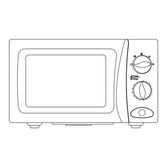
Page 5: Feature Diagram
FEATURES DIAGRAM ¤ Door Hook - When the door is closed, it will automatically shut. If the door is opened while the oven is operating, the magnetron will immediately stop operating. ¤Ł Door Seal - Door seal maintains the microwave energy within the oven cavity and prevents micro leakage. -
Page 6: Installation
INSTALLATION 1. Steady, flat location This microwave oven should be set on a steady, flat surface. 2. Leave space behind and side All air vents should be kept a clearance. If all vents are covered during operation, the oven may overheat and, eventually, cause oven failure. -
Page 7: Operation
OPERATION Connect the mains lead to an electrical socket-outlet. After placing the food in a suitable utensil, open the door and put it on the glass turtable, Glass turntable must always be in place during cooking. In case the oven is operated in the grill mode, use the Metal Rack and place food on the metal Rack. Shut the door. -
Page 8: Measurement Of The Microwave Output Power
4. Microwave power is switched on. 5. Heating time should be exactly 52 sec.(KOG-36A5) or 47 sec.(KOG-38A5). Heating time is measured while the microwave generator is operating at full power. -
Page 9: Microwave Radiation Test
MICROWAVE RADIATION TEST WARNING • Make sure to check the microwave leakage before and after repair or adjustment. • Always, start measuring of an unknown field to assure safety for operating personnel from microwave energy. • Do not place your hands into any suspected microwave radiation field unless the safe density level is known. •... -
Page 10: Wiring Diagram
WIRING DIAGRAM... - Page 11 WIRING DIAGRAM(SLOW ACTING RELAY)
-
Page 12: Circuit Description
CIRCUIT DESCRIPTION 1. When the food is placed in the oven cavity and door is closed. • The contact of the interlock monitor switch open (NO). • The contacts of the primary interlock switch and secondary interlock switch close. Primary Timer Interlock 15A Fuse... - Page 13 Fig. 2 3. When the door is opened during cooking. • Primary interlock switch and secondar interlock switch open to cut off the primary voltage to the high voltage transformer to stop microwave oscillation. • Fan motor, timer motor and turntable motor stop rotating. •...
-
Page 14: Precautions For Disassembly And Repair
PRECAUTIONS FOR DISASSEMBLY AND REPAIR – Cautions to be observed when trouble shooting. Unlike many other appliances, the microwave oven is a high-voltage, high-current equipment. It is completely safety during normal operation. However, carelessness in servicing the oven can result in an electric shock or possible danger from a short circuit. -
Page 15: Disassembly And Assembly
DISASSEMBLY AND ASSEMBLY 1. To remove cabinet. Remove three screws on cabinet back. 2. To remove door assembly. 1) Remove two screws ¤ which secure the stopper hinge top. 2) Remove the stopper hinge top ¤Ł and door assembly ¤Ø from top plate of cavity. 3) Remove the stopper hinge top ¤Łfrom door assembly. - Page 16 (1) Remove the gasket door(A06) from door painting ass’y (A04) (2) Remove the barrier screen inner(A05) from door painting ass’y(A04). (3) Remove the hook spring(A08) and the hook(A07). (4) Remove the hinge stopper top ass’y(A03). (5) Remove the door frame(A01) from door painting ass’y(A04). (6) Remove the barrier screen outer(A02).
- Page 17 5. To remove control panel parts. (1) Remove the screw which secure the control panel push up two snap fits and draw forward the control panel assembly. (2) Remove the screw (B05) which secure the VPC coupler(B04). (3) Pull out the VPC coupler(B04), VPC knob(B01) and the flat spring (B03) from the control panel(B02). (4) Remove two screws(B08) which secure the timer ass’y(B07).
- Page 18 6. To remove high voltage capacitor. (1) Remove a screw ¤ which secure the grounding ring terminal of the H.V. diode ¤Ł and the capacitor holder ¤Ø . (2) Remove the H.V. diode ¤Ł from the capacitor holder ¤Ø . (3) Reverse the above steps for reassembly.
- Page 19 CAUTION : Never install the magnetron without the metallic gasket plate which is packed with each magnetron to prevent microwave leakage. Whenever repair work is carried out on magnetron, check the microwave leakage. It shall not exceed 4mW/cm for a fully assembled oven with door normally cosed. 8.
- Page 20 TRS 5X6 MFCR NUT HEX 7392500008 6N-2-5 SUS SCREW MACHINE 7002400413 TRS 4X4 MFCR 3515000700 KOG-36A5 SPACER INSULATOR * I C3771BD NUT HEX 7392500011 6N-2-5 MFZN (1) Remove the HEX NUT 4. (2) Remove the insulater Heater 1 and Heater 2.
-
Page 21: Interlock Mechanism
INTERLOCK MECHANISM The door lock mechanism is a device which ahs been specially designed to completely eliminate microwave radiation when the door is opened during operation, and thus to perfectly prevent the danger resulting from the leakage of microwave. (1) Primary interlock switch When the door is closed, the hook locks the oven door. - Page 22 (2) Secondary interlock switchand interlock monitor switch When the door is closed, the hook pushes the push lever down ward, the push lever presse the button of the monitor interlock switch to bring it under “off”, condition and presses the button of the secondary interlock switch to biring it under “on”, condition.
-
Page 23: Trouble Shooting Guide
TROUBLE SHOOTING GUIDE Trouble Door shut, timer set but no cooking takes place. Does the fan motor work when you shut the door and turn the timer? Does 15A fuse blow? Replace continuity Check continuity of continuity primary interlock switch, interlock monitor switch secondary interlock switch with door shuted. -
Page 25: Component Test Procedure
(B) Normal readings should be as follows: Reverse the meter leads and again observe the Secondary winding..Approx. 100Ω¡ 10%(KOG-36A5) resistance reading. meter with 6V, 9V or higher ........Approx. 110Ω¡ 5%(KOG-38A5) voltage batteries should be used to check the front- Filament winding........Approx. -
Page 26: Safety Interlock Continuity Test
SAFETY INTERLOCK CONTINUITY TEST ¥ Disconnect the oven from the power supply. ¥ You can test continuity of safety interlocks and monitor switch by using switch tester or ohmmeter. ¥ The switch operation is checked by the lamp on/off of resistance zero/unlimited. ¥... -
Page 27: Exploded And Parts List
EXPLODED AND PARTS LIST 1. Door Assembly DOOR AS : 3511710100 REF NO. PART NAME PART CODE DESCRIPTION Q’TY REMARKS 3512202060 KOG-36A5 FRAME DOOR ABS H-2938 XR-401 3517003080 KOG-36A5 BARRIER-SCREEN *O PC TI.0 STOPPER HINGE *T AS 3515201500 KOR-61150S 3511706100... - Page 28 C-PANEL AS : 3516716070 REF NO. PART NAME PART CODE DESCRIPTION Q’TY REMARKS KNOB VPC 3513402680 ABS H-2938 XR-401 3516709860 KOG-36A5 CONTROL-PANEL ABS H-2938 XR-401 SPRING FLAT 3515101600 SUS 301 T0.5 COUPLER VPC KNOB 3517400500 SCREW TAPPING 7122401211 T2S TRS 4X12 PW MFZN...
- Page 29 3. Main Unit...
- Page 30 PART LIST 3513806850 KOG-38150S LOCK AS 3513807441 KOG-38150S GERMANY for Germany R CEMENT RX10H200K- 10W 20 OHM K SCREW TAPTITE 7272400811 TT3 TRS 4X8 MFZN...
Need help?
Do you have a question about the KOG-36A5 and is the answer not in the manual?
Questions and answers