Table of Contents
Advertisement
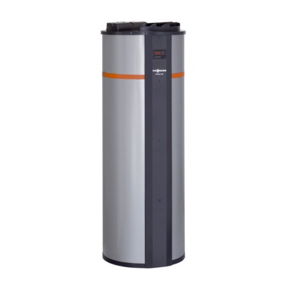
VIESMANN
Technical guide
VITOCAL 160-A
Type WWK
DHW heat pump for circulating or extract air operation
DHW temperatures up to 55 °C with heat pump in operation
Cylinder capacity 285 litres
Air flow rate up to 250 m
3
/h
VITOCAL 160-A
Type WWKS
DHW heat pump as type WWK, with additional internal indi-
rect solar coil and solar control unit
5822 485 GB
12/2008
VITOCAL 160-A
DHW heat pump
Advertisement
Table of Contents

Related Manuals for Viessmann VITOCAL 160-A


Summary of Contents for Viessmann VITOCAL 160-A
- Page 1 VIESMANN VITOCAL 160-A DHW heat pump Technical guide VITOCAL 160-A Type WWK DHW heat pump for circulating or extract air operation DHW temperatures up to 55 °C with heat pump in operation Cylinder capacity 285 litres Air flow rate up to 250 m...
-
Page 2: Table Of Contents
■ Standard ventilation for standard operation .............. 24 ■ Extract/expelled air pipework (accessory) ..............24 Sizing 7.1 Determining the pressure drop for the extract/expelled air pipework (Vitocal 160-A for extract mode) ........................ 26 ■ Flow velocity ......................27 ■ Pressure drop diagram for ventilation elements and expelled air outlets ....28 ■... - Page 3 8.1 Form for designing the sections in the extract/expelled air pipework ......32 8.2 Form for calculating the total pressure drop in the extract/expelled air pipework ..33 8.3 System diagram - extract/expelled air pipework ............34 Keyword index .............................. 35 VIESMANN VITOCAL 160-A...
-
Page 4: Yielding Heating Energy From The Ambient Air
In extract mode the heat pump draws the air through pipework, including air from other rooms. Type WWK (without solar facility) The Vitocal 160-A, type WWK is specially designed for DHW heating without an external heat source (mono-mode or monoenergetic opera- tion). Circulating mode Through the operation of the heat pump the air in the installation room is cooled and the air humidity drops. - Page 5 (cont.) Type WWKS (with solar facility) The Vitocal 160-A, type WWKS is designed for DHW heating with solar backup. The integral indirect solar coil enables the connection of flat- plate collectors up to 6 m area or tube collectors with up to 3 m collector area.
-
Page 6: Noise Development
The sound pressure level is the variable that is used to assess emis- sions from individual systems. VIESMANN VITOCAL 160-A... -
Page 7: Transmission Of Sound In Buildings
In the house itself, there is a risk that airborne noise will be transmitted via stairwells and cellar ceilings amongst others. Note The transfer of noise emitted from the Vitocal 160-A can be signifi- cantly reduced through a series of effective measures (see page 20). -
Page 8: Product Description
200 m The volume of the DHW cylinder of the Vitocal 160-A is 285 l and so Continuous operation enables the on-going ventilation of the rooms is comfortably sufficient for a large family (up to 5 members). - Page 9 (cont.) Conversion to extract mode The cover for circulating mode is also installed with the Vitocal 160-A for extract mode in its delivered state. The conversion to extract mode is made on site by replacing the cover for circulating mode with the delivered cover for extract mode.
-
Page 10: Specification
Vitocal 160-A (cont.) 2.2 Specification Specification Vitocal 160-A Type WWK Type WWKS Heat pump output data when heating domestic water from 15 to 45 °C and air temperature 15 °C Rated heating output 1.52 Coefficient of performance ∊ (COP) 3.54 Electricial output data Electr. -
Page 11: Air Flow Rate Curve
Vitocal 160-A (cont.) Sound power level in circulating mode at air flow rate 250 m Sound power level L [dB (A)] at octave centre frequency [Hz] Total 1000 2000 4000 8000 In installation room Air flow rate curve Flow rate in m³/h... -
Page 12: Expelled Air Apertures
Vitocal 160-A (cont.) Type WWK, WWKS with cover for extract mode Ø 660 BÖ KW/E Extract air (DN 160) HVS Heating water flow, solar thermal system Expelled air (DN 160) KOA Condensate drain BÖ Inspection aperture Cold water Drain connector... -
Page 13: Outside Air Inlet Grille (External Wall Connection)
Part no. 9521 448 ■ Flow rate up to 45 m ■ With installation ring ■ For installation in ceilings and walls in bathrooms, toilets, sanitary rooms and workrooms Note Installation as for kitchen extract air valves (see page 14) VIESMANN VITOCAL 160-A... -
Page 14: Kitchen Extract Air Valve Dn 100
■ Fits the ventilation air valve, part no. 7299 302 ■ Pack containing 10 filters 3.3 Sound insulation and silencer With Vitocal 160-A install a silencer in the pipework upstream of the Irrespective of the building location, according to VDI Directive 2058 appliance. -
Page 15: Silencer Dn 160, Round, Flexible
2000 4000 Hz 8000 Hz Octave centre frequency 3.4 Pipework and moulded parts Flexible pipe DN 160, thermally insulated Part no. 9521 450 ■ Length 2.50 m ■ Thermal insulation made from resin-bonded mineral fibre Ø Ø VIESMANN VITOCAL 160-A... -
Page 16: Flexible Pipe, Compressed
■ To join two flexible pipes Spiral-seam tube DN 125: Part no. 7249 104 DN 160: Part no. 9521 428 ■ Length 3.00 m Ø Bend 90° DN 125: Part no. 7249 106 DN 160: Part no. 9521 431 Ø VIESMANN VITOCAL 160-A... -
Page 17: Tee, Reduced
DN 160: Part no. 7299 293 ■ Outlet 90° ■ Dimensions and connections Part no. 7299 292 DN 125 DN 100 205 mm 7299 293 DN 160 DN 125 230 mm Reducer 160/125 Part no. 7249 108 ■ To connect pipe sections VIESMANN VITOCAL 160-A... -
Page 18: Reducer 125/100
The Vitocal 160-A should preferably be installed within the air tight and thermally insulated building envelope. The Vitocal 160-A for extract mode needs to be positioned so that the pipe to the extract air areas is as short as possible. Those parts of the extract/expelled air pipework that pass through unheated areas of the house, must be insulated with thermal insulation material (with at least 50 mm thickness) safe from the diffusion of vapour. - Page 19 ■ The appliance must be accessible for maintenance purposes. ■ Provide a drain pipe for draining the condensate. ≥ 500 kg Vitocal 160-A Siphon for condensate drain With circulating cover a = 2100 mm With extract cover a = 2200 mm...
-
Page 20: Sound And Vibration Insulation
L Vibration insulation for floor M Adjustable feet 6.3 Electrical connection The Vitocal 160-A is connected to the power supply with a safety socket. This way all electrical components incl. the electric immersion heater are supplied with power. Connection values... -
Page 21: Condensate Drain
The solar flow and return are connected at the connection fittings heating can be even further reduced. (R ¾") on the solar heat exchanger integrated in the Vitocal 160-A. With this in mind the Vitocal 160-A features an integral temperature differential control unit, and the collector temperature sensor is part of the standard delivery. -
Page 22: Hydraulic Diagram
WWKS) H Solar collectors K Safety valve L Expansion vessel A Vitocal 160-A, type WWKS B Integral DHW cylinder with internal solar indirect coil 6.6 Connections on the DHW side For the DHW connection, observe DIN 1988 and DIN 4753. -
Page 23: Ventilation Mode (Vitocal 160-A For Extract Mode)
According to DIN 1988-2, a drinking water filter should be installed in systems with metal pipework. Viessmann also recommends the instal- lation of a drinking water filter when using plastic pipes, as per DIN 1988, to prevent contaminants entering the DHW system. -
Page 24: Operation With Open Flue Combustion Equipment
Operation with open flue combustion equipment Never operate the Vitocal 160-A with extract system together with If a Vitocal 160-A is operated together with an open flue heat source open flue combustion equipment (e.g. open fireplaces). such as the Vitopend or Vitodens, provide an on site fan interlock. This Doors to boiler rooms where the combustion air supply is not inter- must switch the fan off as soon as the heat source starts. - Page 25 ■ Install ventilation pipes, wall outlets and connections with the avoid negative pressure (see pages 4 and 14). Vitocal 160-A (see page 20) using anti-vibration mounts. ■ Install extract and expelled air lines in the immediate vicinity of the ■ To prevent flow noise and increased energy use through pressure heat pump either horizontally or at a slight angle to the extract cover.
-
Page 26: Determining The Pressure Drop For The Extract/Expelled Air Pipework (Vitocal 160-A For Extract Mode)
(on-site). Sizing 7.1 Determining the pressure drop for the extract/expelled air pipework (Vitocal 160-A for extract mode) Dividing the pipework into individual sections and completing the The Vitocal 160-A will only achieve the max. flow rate of 250 m /h if the total pressure drop Δp... -
Page 27: Flow Velocity
Sizing (cont.) A Vitocal 160-A E Extract valves B Silencer F Silencer (optional) to reduce transmission of noise through reflec- C Overflow apertures, e.g. gaps between door frames and door tions ("telephony effect") leaves (gap height min. 0.8 to 1.2 cm) -
Page 28: Pressure Drop Diagram For Ventilation Elements And Expelled Air Outlets
Sizing (cont.) Pressure drop diagram for ventilation elements and expelled air outlets Outside air inlet grille Air flow rate in m³/h Expelled air roof outlet Air flow rate in m³/h VIESMANN VITOCAL 160-A... -
Page 29: Connection Of Solar Collectors And Sizing The Expansion Vessel (Type Wwks)
Vitocal 160-A. Provide pipelines from the collectors to the Vitocal 160-A on site. Also install a pump station (Solar-Divicon) in the To achieve the required pump rate it is necessary to calculate the pressure drop of the pipework including that of the collector area. With solar circuit. -
Page 30: Design And Function Of The Expansion Vessel
22 × 1 0.31 Sizing the expansion vessel The rated volume of the expansion vessel is calculated according to the following equation: (V + V + z · V ) · (p + 1) p - p VIESMANN VITOCAL 160-A... - Page 31 Increase in volume during system heat-up · β = 0.11 litres, selected 3 litres β Expansion factor (β = 0.13 for Viessmann heat transfer medium from –20 to 120 °C) Permissible final pressure in bar (ü) V = V · β...
-
Page 32: Appendix 8.1 Form For Designing The Sections In The Extract/Expelled Air Pipework
8.1 Form for designing the sections in the extract/expelled air pipework Total flow rate max. 250 m Project: Extract air/expelled air area Section Flow rate (´) Pipework Velocity (v) Length Number of bends Number of silenc- Number of tees Pressure drop [m/s] 45º 90º VIESMANN VITOCAL 160-A... -
Page 33: Form For Calculating The Total Pressure Drop In The Extract/Expelled Air Pipework
Pressure drop, expelled air roof outlet: (determine in accordance with the flow rate according to the diagram on page 28) Pressure drop from the expelled air connector on Vitocal 160-A to the blow-off point: (from the table on page 32) Highest pressure drop –... -
Page 34: System Diagram - Extract/Expelled Air Pipework
160/125 7249 108 125/100 7249 109 o. Fig. Extract air valve with mounting ring for installation in ceilings and 9521 448 walls o. Fig. Kitchen extract air valve for installation in ceilings and walls 9542 601 VIESMANN VITOCAL 160-A... -
Page 35: Keyword Index
■ Operational cycle................23 Extract valve..................24 Feet....................20 Fireplace..................24 Fire safety..................23 Fixing clamps...................29 Flexible pipe................15, 20 Floor, min. load-bearing capacity.............19 Flow noise..................25 Flow regulating valve...............23 Flow velocity..................27 Form ■ Designing extract/expelled air sections.........32 ■ Total pressure drop, pipework............33 Fuse....................10 VIESMANN VITOCAL 160-A... - Page 36 Room volume...................19 Mono-mode..................4, 8 Mould....................15 Non-return valve.................22, 23 Normal operation................24 Operating conditions................10 Operating mode.................4 Operating modes................8 Operational cycle................23 Output....................8 output data ■ Heat pump..................10 Output data ■ electrical..................10 Outside air inlet grille..............13, 28 Outside wall outlet................25 Overflow aperture................26 VIESMANN VITOCAL 160-A...
- Page 37 Sound pressure level.................6 Wall outlet..................25 Sound sources...................6 Water seal, expansion vessel............30 Sound transmission data..............10 Weight....................10 Specification..................10 ■ Expansion vessel................30 Spiral-seam tube................16 Splitting air flow................25 Standard ventilation.................24 Standby heat loss................10 Structure-borne noise.................6 System diagram - extract/expelled air pipework......34 VIESMANN VITOCAL 160-A...
- Page 38 VIESMANN VITOCAL 160-A...
- Page 39 VIESMANN VITOCAL 160-A...
- Page 40 Subject to technical modifications. Viessmann Werke GmbH&Co KG Viessmann Limited D-35107 Allendorf Hortonwood 30, Telford Telephone: +49 6452 70-0 Shropshire, TF1 7YP, GB Fax: +49 6452 70-2780 Telephone: +44 1952 675000 www.viessmann.com Fax: +44 1952 675040 E-mail: info-uk@viessmann.com VIESMANN VITOCAL 160-A...
Need help?
Do you have a question about the VITOCAL 160-A and is the answer not in the manual?
Questions and answers