Table of Contents
Advertisement
Quick Links
Advertisement
Table of Contents

Subscribe to Our Youtube Channel
Related Manuals for Peak IPEH-003044


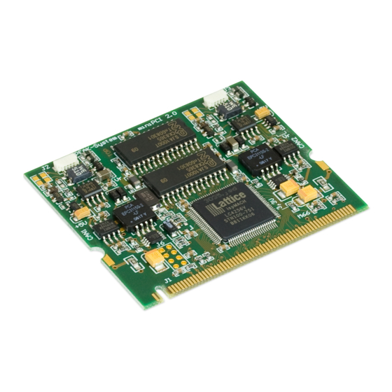
Summary of Contents for Peak IPEH-003044
- Page 1 PCAN-miniPCI Mini PCI to CAN Interface User Manual V2.1.1...
- Page 2 All other product names mentioned in this document may be the trademarks or registered trademarks of their respective companies. They are not explicitly marked by “™” and “®”. © 2012 PEAK-System Technik GmbH PEAK-System Technik GmbH Otto-Roehm-Strasse 69 64293 Darmstadt...
-
Page 3: Table Of Contents
PCAN-miniPCI – User Manual Contents Introduction Properties at a Glance System Requirements Scope of Supply Installing the Software and the Card Connecting the CAN Bus D-Sub connector Supplying External Devices via the CAN Connector Cabling 3.3.1 Termination 3.3.2 Example of a Connection 3.3.3 Maximum Bus Length Using the Software... -
Page 4: Introduction
PCAN-miniPCI – User Manual Introduction The PCAN-miniPCI card provides one or two CAN channels in com- puters with Mini PCI slots (e.g. in the embedded domain). Device drivers and programming interfaces exist for different operating systems, so programs can easily access a connected CAN bus. Tip: At the end of this manual (Appendix C) you can find a Quick Reference with brief information about the installation... -
Page 5: System Requirements
Windows. You can find device drivers for Linux and the corresponding application information on the provided CD in the directory branch Develop and on our website under www.peak-system.com/linux. System Requirements A vacant Mini PCI slot in the computer Operating system Windows 7/Vista/XP (32/64-bit) or Windows CE6.x (x86 and ARMv4 processor support) -
Page 6: Installing The Software And The Card
PCAN-miniPCI – User Manual Installing the Software and the Card This chapter covers the software setup for the PCAN-miniPCI card under Windows and the installation in the computer. Setup the driver before installing the PCAN-miniPCI card. Do the following to install the driver: Windows XP only: Make sure that you are logged in as user with administrator privileges (not needed for normal use of the PCAN-miniPCI card later on). - Page 7 PCAN-miniPCI – User Manual Do the following to install the card in the computer: Attention! Electrostatic discharge (ESD) can damage or destroy components on the PCAN-miniPCI card. Take precautions to avoid ESD when handling the card. Shut down the computer. Disconnect the computer from the power supply.
- Page 8 PCAN-miniPCI – User Manual Do the following to complete the initialization: Turn on the computer and start Windows. Make sure that you are logged in as user with administrator privileges. Windows notifies that new hardware has been detected. Windows XP only: A Wizard dialog box appears. Follow its instructions.
-
Page 9: Connecting The Can Bus
You can find a detailed description in the follo- wing section 3.2. Tip: You can connect a CAN bus with a different transmission standard via a bus converter. PEAK-System offers different bus converter modules (e.g. PCAN-TJA1054 for a Low-speed CAN bus according to ISO 11898-3). - Page 10 PCAN-miniPCI – User Manual Figure 3: PCAN-miniPCI card with connection cable To connect a CAN bus to the PCAN-miniPCI card, use the supplied special connection cables. After you've plugged in the cable on the PCAN-miniPCI card, you can connect a CAN bus to the D-sub socket.
-
Page 11: Supplying External Devices Via The Can Connector
PCAN-miniPCI – User Manual Supplying External Devices via the CAN Connector A 5-Volt supply can optionally be routed to pin 1 of a D-Sub connec- tor on the PCAN-miniPCI card (independently for each connector on the Dual Channel versions). Thus devices with low power consump- tion (e.g. - Page 12 PCAN-miniPCI – User Manual CAN 1 CAN 2 Figure 4: Positions of the solder fields on the PCAN-miniPCI card 5-Volt supply → None Pin 1 CAN channel 1 (left, near J2) CAN channel 2 (right, near J3) Attention! Risk of short circuit! If the option described in this section is activated, you may only connect or disconnect CAN cables or peripheral systems (e.g.
-
Page 13: Cabling
PCAN-miniPCI – User Manual Cabling 3.3.1 Termination A High-speed CAN bus (ISO 11898-2) must be terminated on both ends with 120 Ohms. Otherwise, there are interfering signal reflections and the transceivers of the connected CAN nodes (CAN- interface, control device) will not work. The PCAN-miniPCI card does not have an internal termination. -
Page 14: Maximum Bus Length
PCAN-miniPCI – User Manual 3.3.3 Maximum Bus Length High-speed CAN networks may have bit rates of up to 1 Mbit/s, where all CAN nodes must be able to process messages simultaneously. The maximum bus length depends primarily on the bit rate. The following table shows the maximum possible CAN bus length at different bit rates: Bit rate... -
Page 15: Using The Software
PCAN-miniPCI – User Manual Using the Software This chapter covers the provided software PCAN-View and the programming interface PCAN-Basic. CAN Monitor PCAN-View for Windows PCAN-View for Windows is a simple CAN monitor for viewing, transmitting, and logging CAN messages. Figure 6: The main window of PCAN-View for Windows Do the following to start and initialize PCAN-View: If PCAN-View is already installed on the hard disk, open the Windows Start menu, go to Programs >... - Page 16 PCAN-miniPCI – User Manual CD. In the navigation program (Intro.exe), go to English > Tools, and under PCAN-View for Windows select the link Start. The dialog box for selecting the CAN hardware and for setting the CAN parameters appears. Figure 7: Selection of the CAN hardware and parameters From the list Available CAN hardware select the CAN channel to be used.
-
Page 17: Receive/Transmit Tab
PCAN-miniPCI – User Manual 4.1.1 Receive/Transmit Tab Figure 8: Receive/Transmit Tab The Receive/Transmit tab is the main element of PCAN-View. It contains two lists, one for received messages and one for the transmit messages. Representation of CAN data is in hexadecimal format. - Page 18 PCAN-miniPCI – User Manual Figure 9: Dialog box New transmit message Enter the ID and the data for the new CAN message. The field Cycle Time indicates if the message shall be transmitted manually or periodically. If you want to transmit the message periodically, you must enter a value greater than 0.
-
Page 19: Trace Tab
PCAN-miniPCI – User Manual 4.1.2 Trace Tab Figure 10: Trace Tab On the Trace tab the data tracer of PCAN-View is used for logging the communication on a CAN bus. During this process the CAN messages are cached in the working memory of the PC. Afterwards they can be saved to a file. -
Page 20: Status Bar
PCAN-miniPCI – User Manual 4.1.3 Status Bar Figure 11: Display of the Status Bar The status bar shows information about the current CAN connection, about error counters (Overruns, QXmtFull) and shows error messages. You can find further information about the use of PCAN-View in the help which you can invoke in the program via the menu Help or the F1 key. -
Page 21: Linking Own Programs With Pcan-Basic
On the provided CD you can find files of the programming interface PCAN-Basic in the directory branch Develop. This API provides basic functions for linking own programs to CAN interfaces by PEAK-System and can be used for the following operating systems: Windows 7/Vista/XP (32/64-bit) Windows CE 6.x (x86/ARMv4) The API is designed for cross-platform use. -
Page 22: Features Of Pcan-Basic
Use of up to 8 channels for each hardware unit (depending on the PEAK CAN interface used) Simple switching between channels of a PEAK CAN interface Driver-internal buffering of 32,768 messages per CAN channel Precision of time stamps on received messages up to 1 μs... -
Page 23: Principle Description Of The Api
PCAN-miniPCI – User Manual 4.2.2 Principle Description of the API The PCAN-Basic API is the interface between the user application and device driver. In Windows operating systems this is a DLL (Dynamic Link Library). The sequence of accessing the CAN interface is divided into three phases: 1. -
Page 24: Notes About The License
Notes about the License Device drivers, the interface DLL, and further files needed for linking are property of the PEAK-System Technik GmbH and may be used only in connection with a hardware component purchased from PEAK-System or one of its partners. If a CAN hardware component... -
Page 25: Technical Specifications Pcan-Minipci
PCAN-miniPCI – User Manual Technical Specifications PCAN-miniPCI Connectors Computer Mini PCI, type 3A (124-pin) D-Sub (m), 9 pins Pin assignment according to specification CiA® 102 Specification ISO 11898-2, High-speed CAN 2.0A (standard format) and 2.0B (extended format) Bit rates 40 kbit/s - 1 Mbit/s Lower bit rates on request Controller NXP (Philips) SJA1000... - Page 26 PCAN-miniPCI – User Manual Measures Size 59.6 x 51 x 4 mm (W x L x H) See also dimension drawing in Appendix B on page 28. Weight Card Cable + D-Sub PCAN-miniPCI Single Ch.: 10 g PCAN-miniPCI Dual Ch.: 11 g 16 g PCAN-miniPCI Single Ch.
-
Page 27: Appendix Ace Certificate
PCAN-miniPCI – User Manual Appendix A CE Certificate... -
Page 28: Appendix B Dimension Drawing
PCAN-miniPCI – User Manual Appendix B Dimension Drawing Figure 13: View PCAN-miniPCI The figure doesn’t show the actual size of the product. -
Page 29: Appendix C Quick Reference
PCAN-miniPCI – User Manual Appendix C Quick Reference Software/Hardware Installation under Windows Before installing the PCAN-miniPCI card into the computer set up the corresponding software package from the supplied CD (with administrator privileges). Afterwards, insert the PCAN-miniPCI card into a vacant Mini PCI slot of the switched off computer. The PCAN- miniPCI card is recognized by Windows and the driver is initialized.
Need help?
Do you have a question about the IPEH-003044 and is the answer not in the manual?
Questions and answers