LXNAV LX90xx User Manual
With variometer
Hide thumbs
Also See for LX90xx:
- System installation manual (65 pages) ,
- User manual (192 pages) ,
- Installation manual (69 pages)

Related Manuals for LXNAV LX90xx


Summary of Contents for LXNAV LX90xx
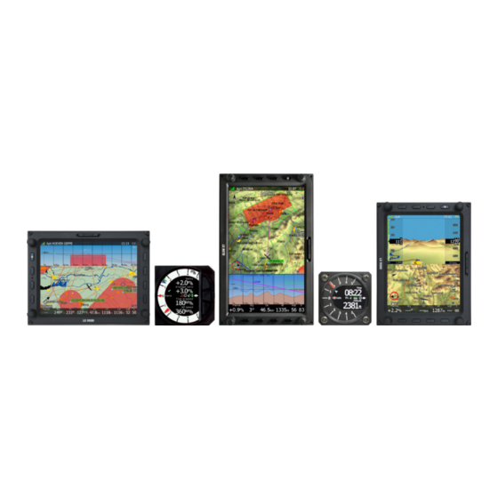
- Page 1 LX90xx GPS-Navigation System with variometer (Including LX9000 and LX9070) Version 4.0 LXNAV d.o.o. • Kidričeva 24a, 3000 Celje, Slovenia • tel +386 592 33 400 fax +386 599 33 522 info@lxnav.com www.lxnav.com •...
-
Page 3: Table Of Contents
LX90xx system Version 4.0 February 2014 Important Notices Limited Warranty Basics The LX9xx series at a glance 2.1.1 LX9000 Display Unit Features 2.1.2 LX9070 Display Unit Features 2.1.3 V9 Vario Unit Features 2.1.4 V80 Vario Unit Features 2.1.5 Interfaces 2.1.6 Internal Options 2.1.7... - Page 4 LX90xx system Version 4.0 February 2014 6.1.1 QNH and RES 6.1.1.1 QNH* 6.1.1.2 Safety Altitude 6.1.1.3 Altitude source 6.1.1.4 Magnetic Variation 6.1.1.5 ETA/ETE Calculation 6.1.1.6 Soaring Start* 6.1.2 Flight Recorder 6.1.3 Vario Parameters* 6.1.4 Display 6.1.5 Files and Transfers 6.1.5.1 Uploading User Airspace and Waypoints 6.1.5.2...
- Page 5 LX90xx system Version 4.0 February 2014 6.1.12.10 AHRS 6.1.12.11 NMEA Output 6.1.12.12 Engine * 6.1.12.13 Flaps* 6.1.13 Polar and Glider* 6.1.14 Profiles and Pilots 6.1.15 Language 6.1.16 Passwords 6.1.17 Admin mode 6.1.18 About Information Mode 6.2.1 GPS Status Page 6.2.2 Position Report 6.2.3...
- Page 6 LX90xx system Version 4.0 February 2014 6.7.5.2 Below Altitude Start Procedure 6.7.5.3 Maximum Start Speed and/or Maximum Start Altitude 6.7.6 Saving a Task 6.7.7 Loading a Task 6.7.8 Moving a Task Point Navigational page layout Global styles for navigational page Creating new symbol 7.2.1...
- Page 7 LX90xx system Version 4.0 February 2014 ® 11.7 Flap sensor 11.8 Secondary Vario Indicators Revision History Page 7 of 151...
-
Page 8: Important Notices
LXNAV retains the exclusive right to repair or replace the unit or software, or to offer a full refund of the purchase price, at its sole discretion. SUCH REMEDY SHALL BE YOUR SOLE AND EXCLUSIVE REMEDY FOR ANY BREACH OF WARRANTY. -
Page 9: Basics
LX90xx system Version 4.0 February 2014 Basics 2.1 The LX9xx series at a glance LX9xx series of instrument consists of two units; the main display unit and the vario unit. Within the main display unit an integral 50-channel GPS receiver and a high brightness colour display are fitted. -
Page 10: Lx9070 Display Unit Features
LX90xx system Version 4.0 February 2014 Portrait or landscape orientation. • Pre-loaded with worldwide terrain maps, airspace and airport databases. • Unlimited number of waypoints. • Unlimited number of tasks (with assigned area support). • Comprehensive flight and task statistics. -
Page 11: V9 Vario Unit Features
LX90xx system Version 4.0 February 2014 Flight recorder functions include an integral pressure transducer based on 1013 mbar • level for altitude recording, engine noise level sensor, memory to store more than 1000 hours of flights and digital and mechanically security devices to ensure high level of security. -
Page 12: Interfaces
LX90xx system Version 4.0 February 2014 Additional Flarm radar screen and artificial horizon. • Three buttons for toggling between screen and target selection • digital temperature compensated pressure sensors for altitude and airspeed • inertial platform 3 axis digital +-6g accelerometer, 4 gyroscopes •... -
Page 13: External Options
By using a RS485 bus system a wide range of optional interfaces can be easily connected to the basic configuration with minimal installation work. The LXNAV bus system can be extended easily by use of RS485 splitting units, which allow plug and play connection of optional devices. -
Page 14: Simulator
LX90xx system Version 4.0 February 2014 2.1.8 Simulator There are two options to stay in condition and familiar with your LX90xx system. LXSim is free of charge program, which you can download from www.lxnav.com or data from the Condor PC flight simulator (www.condorsoaring.com) can be received via the RS232 port after entering suitable passwords (see Chapter 6.1.15). -
Page 15: Packing Lists
LX90xx system Version 4.0 February 2014 Packing Lists 3.1 LX9000 (LX9070) with Flarm Option LX9000 (LX9070) main display unit • V9 vario unit with V5 indicator or with V80 indicator • Main power cable for main display unit • Cable for vario unit •... -
Page 16: Installation
LX90xx system Version 4.0 February 2014 Installation The main display unit is installed in an aperture 93.5 mm wide and 81.5 mm high. The vario unit and any additional vario indicators each require a standard 57 mm cut-out or standard 80 mm cut out. -
Page 17: Panel Cut-Out For V9/V5 Vario Unit
LX90xx system Version 4.0 February 2014 4.2 Panel cut-out for V9/V5 vario unit 4.3 Panel cut-out for V80 vario unit Length of screw is limited to max 6mm! 4.4 Pneumatic connection Three pressure connectors are fitted to the back of the vario unit. A label shows their functions. -
Page 18: Ports And Wiring
LX90xx system Version 4.0 February 2014 TE/P TE tube • static Static • static Pitot or Total pressure • total If the P and Static are connected the wrong way around there will be no total integrator reading (average climb) during the flight. -
Page 19: Flarm Port
LX90xx system Version 4.0 February 2014 4.5.1 Flarm port 1 2 3 4 5 6 Pin numbers Pin number Description (output) 12V DC, to supply GPS (output) 3.3V DC (max 100mA) Flarm Data Out Flarm Data In Ground 4.5.2 Main unit wiring... -
Page 20: V5/V9/V80 Vario Unit Wiring
LX90xx system Version 4.0 February 2014 4.5.3 V5/V9/V80 vario unit wiring yellow LABEL:RS485 (green) RS485 - IN +12V white SUBD9 / male 30 cm (Brown) black shield 50 cm LABEL:IN-1 INPUT1 - GEAR Closed, when gear is down GND SHIELD... -
Page 21: Lx90Xx System Version 4.0 February
LX90xx system Version 4.0 February 2014 installation work. The main display unit also powers all devices connected to the bus. An automatic fuse built into the main display unit prevents damage to the digital unit should a short circuit in the wiring or in some attached device occurs. -
Page 22: System Description
LX90xx system Version 4.0 February 2014 System Description The main display unit can be mounted at portrait or landscape orientation. After installing the main display unit, the orientation must be defined via the Display menu (see Chapter 6.1.4). In this manual all screenshots are given for portrait orientation of the LX9000 system. -
Page 23: Portrait Orientation
LX90xx system Version 4.0 February 2014 5.1.2 Portrait orientation VOLUME selector MODE selector Ambient light POWER button sensor SD Card reader PAGE selector ZOOM selector The V9 vario unit is an indicator only and has no controls. Information displayed is controlled by the main display unit. -
Page 24: Switching On The Unit
The final boot screen displays information about the LX90xx system firmware and the IGC serial number. When the boot procedure is completed the profile selection dialogue is shown. Please refer to Chapter 8.1 for more details about starting up the system. -
Page 25: Text Edit Control
LX90xx system Version 4.0 February 2014 5.3.1 Text Edit Control The Text Editor is used to input an alphanumeric string of arbitrary length; the picture below shows typical options when editing text. Use the bottom-right knob to change the value at the current cursor position. -
Page 26: Spin Control
LX90xx system Version 4.0 February 2014 5.3.3 Spin Control Spin controls are designed for numeric parameters. Rotate the bottom-right knob (page selector) to increase/decrease the selected value. The bottom-left (zoom) knob will increase/decrease the value with a different step compared to the page selector. -
Page 27: Font Selector
LX90xx system Version 4.0 February 2014 Rotating the zoom selector changes colour transparency. Transparency is very important for fill colours which are used for airspace zones, observation zones and FAI area. If a fill colour is not transparent (0%), all other map items will not be seen through it. If a fill colour is 100% only the solid border will be drawn. -
Page 28: Switching Off
LX90xx system Version 4.0 February 2014 5.4 Switching off Please use one of the following recommended methods for shutting down the LX90xx system: Method 1 Press the button with the OFF label which is displayed in navigational modes. See Chapter 6.5 for more details. - Page 29 LX90xx system Version 4.0 February 2014 If the request for OFF is made during flight the instrument will ask for confirmation so that the system cannot be switched off by mistake. It is important that the main display unit is switched off via software. Never power down the system using the main power switch.
-
Page 30: Operating Modes
LX90xx system Version 4.0 February 2014 Operating Modes The main display unit has seven modes or main menus. All of them are selectable by rotating the upper-right knob which is also called MODE selector. The diagram below shows the mode structure of the LX9000 running in portrait screen. - Page 31 It is also possible to customise selected navigational pages using STYLE menu option. Refer to Chapter 7 for more details. In airport navigation mode the user can navigate only to airports stored in LXNAV's Airports database. This database cannot be edited on device itself and is available at no charge on our web pages.
-
Page 32: Setup Mode
LX90xx system Version 4.0 February 2014 6.1 Setup Mode In the setup menu users can configure the main display unit and connected devices. Turn the bottom-right knob - PAGE selector - or press the UP/DOWN arrow on the remote stick to select the appropriate setup item. -
Page 33: Safety Altitude
LX90xx system Version 4.0 February 2014 6.1.1.2 Safety Altitude This setting is the altitude reserve or safety altitude and is the height that the instrument adds to the final glide altitude required so that the glider arrives over the final glide destination at the selected safety altitude. -
Page 34: Flight Recorder
LX90xx system Version 4.0 February 2014 6.1.2 Flight Recorder The main display unit has a built-in flight recorder fully approved by the IGC (a sub- committee of the FAI) and will produce secure flight records that are acceptable for all FAI requirements including world records. -
Page 35: Vario Parameters
LX90xx system Version 4.0 February 2014 6.1.3 Vario Parameters* This option is used to set the following parameters: On this page the following parameters are set: Vario needle filter sets a time constant of the vario needle. The value can be adjusted between 0.1 and 5 s with step 1.0 s or 0.1 s. -
Page 36: Display
LX90xx system Version 4.0 February 2014 Relative filter sets a time constant of relative vertical speed filter (also known as supper netto vertical speed). The value can be up to 20 times bigger than vario needle filter. Default value is same as vario needle filter. -
Page 37: Files And Transfers
LX90xx system Version 4.0 February 2014 6.1.5 Files and Transfers The Files and transfer menu is used to manage the waypoint, airspace and airport databases, recorded flights, flight declaration and PDF documents. Within a profile user can selected different airport databases, airspace and waypoint files. -
Page 38: Uploading Airspace And Airports Database
6.1.5.2 Uploading Airspace and Airports Database LXNAV distributes free of charge airport and airspace database for the whole world. The airport and airspace database is regularly maintained by LXNAV. The latest version of the database can be found on our webpage www.lxnav.com. - Page 39 LX90xx system Version 4.0 February 2014 To delete airspace file select the airspace item and press the DELETE button. Delete action must be confirmed. Only user airspace files can be removed. Press TO USB button to copy selected airspace to USB stick. Press TO SD button to copy selected airspace to SD card.
-
Page 40: Managing Waypoints
LX90xx system Version 4.0 February 2014 Press EDIT to edit data for the selected zone. Airspace type, class and altitude borders can be modified in this dialogue. 6.1.5.4 Managing Waypoints Select the Waypoints and Tasks menu item and press the SELECT button. A list of all available waypoint files will be shown on the screen. -
Page 41: Managing Airports
LX90xx system Version 4.0 February 2014 If waypoints file from SD or USB are selected button LOAD is visible. Press the LOAD button to upload selected waypoint file to internal storage. If waypoints file from internal storage is selected button SAVE is visible. Press the SAVE button to save waypoints to the SD Card or USB stick. -
Page 42: Managing Airports Using The Lx Asapt Editor
6.1.5.6 Managing Airports Using the LX Asapt editor LX Asapt Editor allows you to edit any LXNAV airport database distributed as asapt files. You can quickly filter the regions and find the airports you're interested in. View and edit all details of the airports, add charts, photos (from files or clipboard) and any other information you would like associated with them. -
Page 43: Managing Maps
LX90xx system Version 4.0 February 2014 6.1.5.7 Managing Maps Main display unit is preloaded with terrain and vector map data for complete Earth. However it is also possible to use scanned (rasterized) maps as background of navigational screen. Next two images are showing example of scanned ICAO map and satellite imagery. -
Page 44: Managing Flights
LX90xx system Version 4.0 February 2014 When a map file from USB or SD card is selected, it will be available only, if SD card or USB stick is inserted in main display unit. Map files can be very big in size and can occupy a lot of space of internal storage of main display unit. -
Page 45: Formatting A Sd Card
LX90xx system Version 4.0 February 2014 On the screen pilot, glider and task information are shown. Press the SAVE button to save the declaration onto a SD card or USB stick. Press the LOAD button for loading. If Nano flight recorder is connected to USB port, TO NANO button will appear. Press it to transfer declaration to Nano flight recorder. - Page 46 LX90xx system Version 4.0 February 2014 Press SELECT button again to open selected document. A document will load within few seconds. Use PAGE selector or NEXT and PREVIOUS button to move up/down through document. Use ZOOM selector to zoom current page. Use MODE selector to move left/right on the selected page.
-
Page 47: Graphics
LX90xx system Version 4.0 February 2014 6.1.6 Graphics This dialogue allows the user to define the appearance of the map in navigational mode. Select the Graphics menu item and press the SELECT button. A submenu will open. 6.1.6.1 Terrain and Map The main display unit is pre-loaded with terrain and vector maps for the Earth. -
Page 48: Airspace
LX90xx system Version 4.0 February 2014 Colours of terrain can be changed using different terrain colour schemes. The following colour schemes are available: Mountain is default setting with colours from green to white at 2000 m. • Flatland is setting where colours are changing up to 1000 m. -
Page 49: Waypoints And Airports
LX90xx system Version 4.0 February 2014 completely transparent and only the airspace zone outline will be shown. 0% means completely solid (not recommended). Image below shows example of combinations of Width and Colour property and rendering of airspace zone. Press the DEFAULT button to reset these settings back to default. -
Page 50: Glider And Track
LX90xx system Version 4.0 February 2014 Code: will display the ICAO code or short name. • Elevation: shows waypoint elevation. • Arrival altitude shows arrival altitude taking into account current MacCready setting, • safety altitude and current wind. Due to complexity of the calculation it will not take the wind profile into account. -
Page 51: Optimization
LX90xx system Version 4.0 February 2014 and therefore not enough altitude to reach the target with the current glider settings. Font Style, Colour and Size define what font for terrain collision altitude and range circles. Enable Show range circles to plot range circles around aircraft symbol. Having range circles on navigational screen, it is much easier to guess distance to nearest point of interest. -
Page 52: Task
LX90xx system Version 4.0 February 2014 6.1.6.6 Task Use this dialogue to define how a task is drawn in task mode. Task colour defines the colour of task lines. Obs.zone colour defines colours for observation zones. Use the ZOOM selector knob to change transparency of area. 100% means completely transparent and only the outline will be drawn. - Page 53 LX90xx system Version 4.0 February 2014 The colour for aircraft that are less than 100 meters below or above your current altitude is defined by the Near Colour item. When a signal from a particular aircraft is lost the aircraft remains blinking on the screen for the duration defined in the Lost device after item (default 120 seconds).
-
Page 54: Sounds
LX90xx system Version 4.0 February 2014 6.1.7 Sounds* In the Sounds setup page audio settings, voice settings and alarms settings for the vario unit can be modified. 6.1.7.1 Audio Settings* Basically here we can set up two types of audio; audio sound for climb mode and another for cruise mode (SC). -
Page 55: Voice
LX90xx system Version 4.0 February 2014 SC audio mode has four modes: SC positive: sound is interrupted with silence every few milliseconds when the needle • is positive; on negative side sound is linear (not interrupted). SC negative: inverse function to SC positive. - Page 56 LX90xx system Version 4.0 February 2014 Frequency and Periods define the length and pitch of alarm. Press DEMO button to play alarm sound. Change volume to define loudness of alarm. Volume level (loudness) can be also set with volume rotary knob, when alarm is...
-
Page 57: Observation Zones
LX90xx system Version 4.0 February 2014 6.1.8 Observation Zones This menu defines the default observation zone geometry. The following items can be chosen: start zone, turn point zone, finish zone and templates. Each type of observation zone is defined with two angles, two radii and mean bearing (Angle12). - Page 58 LX90xx system Version 4.0 February 2014 increase the radius by 0.1 of the selected distance units and the ZOOM selector knob to increase the radius by 5. If Line is not checked the Angle1 parameter will define the basic shape of the observation zone.
-
Page 59: Optimization
LX90xx system Version 4.0 February 2014 6.1.9 Optimization During flight the system optimises the flown path according to OLC or FAI rules. Use this dialogue to change the way instrument performs this optimisation. Number of points defines the type of optimisation. Use five for OLC optimisation. Use the value three for FAI free flight optimisation. -
Page 60: Airspace Warnings
LX90xx system Version 4.0 February 2014 6.1.10.1 Airspace Warnings Airspace warnings are the most complex ones. An airspace warning is activated by two triggers; First warning (orange) will be given when a projected position of flight for period, which is defined in the Time item, is computed to cross an airspace zone. -
Page 61: Altitude Warning
LX90xx system Version 4.0 February 2014 6.1.10.2 Altitude Warning Altitude warnings will be enabled if Show warning is checked. Altitude is given in MSL. Projection is calculated based on the 20 second average vertical speed and time which is defined in the Time item. -
Page 62: Flarm Warnings
LX90xx system Version 4.0 February 2014 6.1.10.3 Flarm Warnings Flarm warnings will be raised only when system is receiving FLARM data from internal or external FLARM module. Using this dialogue the user can define which warnings will be shown and how they are going to be shown. There are three types of warnings: Traffic warnings will be raised once a new aircraft is detected by FLARM. -
Page 63: Time Alarm
LX90xx system Version 4.0 February 2014 6.1.10.4 Time Alarm Use this dialogue to define three independent time alarms that will be triggered at specified periods. 6.1.11 Units Use this dialogue to specify units, UTC time offset and type of ballast input. -
Page 64: Hardware
LX90xx system Version 4.0 February 2014 6.1.12 Hardware* Use this menu to define hardware properties such as total energy compensation, vario indicators layout, compass calibration, FLARM module settings, AHRS settings, NMEA output and data which will be exchanged between the rear and front display units. Some items may be greyed out when the selected option is not available. - Page 65 LX90xx system Version 4.0 February 2014 If the digital TE option has been used TE compensation should be set to 100%. It is important to note that the method of TE compensation is set up when the instrument is installed by virtue of the pneumatic connections made to the TE and static ports.
-
Page 66: Vario Indicator Setup
LXNAV is highly recommending upgrading old LCD or USB-D type of vario unit to latest technology vario unit. Please contact local dealer or LXNAV for more details. -
Page 67: Vario Indicator V5
LX90xx system Version 4.0 February 2014 6.1.12.3 Vario indicator V5* V5 Vario indicator is having mechanical needle and colour screen with 320x240 pixels resolution on which user selectable data are displayed. Each V5 vario indicator is identified by a serial number, which is also displayed on hardware menu. -
Page 68: Vario Indicator V80Mm
LX90xx system Version 4.0 February 2014 Green T symbol represents last thermal average value. White bar displays arc between minimum and maximum vertical speed value in last 20 seconds in white colour or minimum and maximum g-load in red colour, depending on settings. -
Page 69: Lcd And Usb-D Vario Indicator
LX90xx system Version 4.0 February 2014 Press middle button for long time to enter setup menu. In setup menu it is possible to setup graphic interface for Flarm radar screen and numeric values. Numeric screen can also be setup on main display unit. -
Page 70: Flarm
LX90xx system Version 4.0 February 2014 6.1.12.6 Flarm* On the Flarm setup page, information about built in or external Flarm are visible. Information like serial number, selected frequency, firmware version and database versions are shown. EXTERNAL FLARM If Flarm module is built in user can select operation mode. There are three different operational modes available: Power OFF - Flarm unit is switched off. -
Page 71: Compass
LX90xx system Version 4.0 February 2014 6.1.12.7 Compass* When a compass is connected to the system calibration is crucial for correct operation. Refer to compass manual for more info about installation and its calibration. 6.1.12.8 Rear Seat or Front Seat In a two-seat configuration with the rear seat device it is possible to transfer selected data between the front and rear seat device. -
Page 72: Remote Stick
When a remote stick is connected to the system, it is possible to define type of remote stick via this menu. In case LXNAV remote stick with six buttons is connected, user can specify functionality of function button. There are several options available for function button: Toggle vario range will toggle between vario range 2.5m/s, 5m/s or 10m/s. -
Page 73: Ahrs
Data is divided into three groups: GPS data will output all GPS-related data such as time, longitude and altitude. • LXNAV data will output all variometer-related data such as vario, MacCready and • ballast. Flarm data will output all Flarm-related data. -
Page 74: Engine
LX90xx system Version 4.0 February 2014 NMEA data is available also on Flarm display port on main display unit and rear display unit at 19200bps. However only Flarm data and GPS data. 6.1.12.12 Engine * Use this menu, when the system is installed into glider with engine. The current engine noise level is shown as a progress bar. -
Page 75: Polar And Glider
LX90xx system Version 4.0 February 2014 6.1.13 Polar and Glider* Use this dialogue to enter glider polar and other properties of glider. As default polar a standard class glider is selected. Polars for most modern gliders are already prepared. Press the LIST button and a dialogue with a list of all available gliders will be shown. -
Page 76: Profiles And Pilots
LX90xx system Version 4.0 February 2014 the pilot of the maximum take-off weight. Empty weight is weight of the glider without pilot and ballast. The overload factor is calculated as: Empty glider weight Pilot weight Water ballast overload REFERENCE glider weight Pilot weight is set in the Flight recorder menu (see Chapter 6.1.2). - Page 77 A profile file can be opened and manipulated with the LXStyler program. LXStyler is a special program designed to customise layout navigational pages. It can be downloaded free of charge from our web pages www.lxnav.com. For more information about LXStyler please refer to the LXStyler manual.
-
Page 78: Language
LX90xx system Version 4.0 February 2014 If new profile is created with LX Styler, it will have default device settings. However, it is possible to copy device settings from profile to another profile. Select newly created profile as active profile. Select profile from which you would like to copy settings to active profile. -
Page 79: Passwords
LX90xx system Version 4.0 February 2014 6.1.16 Passwords There are several passwords which run specific procedures as listed below: 00111 displays information about the system and its sensors. • 01043 will perform “Auto zero” and set indicated speed to zero. - Page 80 LX90xx system Version 4.0 February 2014 Change Wind Methods, user will not be able to change methods for wind • calculation. Change Page Style, it is not possible to change page layout • Change Flarm Target, user can not change flarm targets names and other data for •...
-
Page 81: About
LX90xx system Version 4.0 February 2014 6.1.18 About About dialogs shown current serial number end version info od the main display unit. Use this menu, whenever you are experienced a problem with the system. If SD card is inserted into the main display unit, button TO SD will be shown. Press TO SD and a report will be saved to SD card. -
Page 82: Position Report
LX90xx system Version 4.0 February 2014 Waypoint data can be modified. Refer to Chapter 6.6.1 for more details. Press the OK button to save a marked waypoint or press CANCEL to exit without saving. Press GOTO button to navigate immediately to selected point. -
Page 83: Satellite Sky View
LX90xx system Version 4.0 February 2014 6.2.3 Satellite Sky View Information about tracked satellites is given on this page. If no satellite information is available a message “No satellite info” is displayed. Green satellites are satellites currently being used for position determination. -
Page 84: Statistics Mode
LX90xx system Version 4.0 February 2014 Small rectangle in bottom right corner of point icons indicates that selected point is having images. 6.4 Statistics Mode The Statistics mode operates in two different ways. During flight statistical data for the current flight is shown whilst on the ground the logbook for all stored flights is displayed. -
Page 85: Statistics During Flight
LX90xx system Version 4.0 February 2014 A map with flown path is shown and barogram. Use ZOOM selector knob to zoom in or zoom out flight. Use PAGE selector knob to move through flight. 6.4.2 Statistics during flight Main statistics page is split into two parts. In top part, last four thermals are shown. -
Page 86: General Statistics
LX90xx system Version 4.0 February 2014 6.4.2.1 General statistics Using the PAGE selector knob the user can change the statistics subpage. There are three subpages available: Flight statistics displays data for whole flight. Dis.flown is the optimised distance. • XC speed is average speed corrected for altitude difference. Average vario is used in this calculation. -
Page 87: Olc Statistics
LX90xx system Version 4.0 February 2014 6.4.2.3 OLC statistics Using the PAGE selector knob the user can select different optimized points. Press VIEW button to show more details for selected optimized leg. Page 87 of 151... -
Page 88: Airport Mode
LX90xx system Version 4.0 February 2014 6.5 Airport Mode Using the PAGE selector knob you can scroll through the pages. There are several navigational pages available. Navigational pages can be customised using LXStyler. The description below applies to the default navigational pages. -
Page 89: Final Glide Symbol
LX90xx system Version 4.0 February 2014 rectangle will be displayed on the magenta line. The green rectangle represents the position from where you will achieve the final glide with current altitude and current MacCready setting. The yellow rectangle represents the position from where you will achieve the final glide with current altitude and MacCready zero. -
Page 90: Second Navigation Page
LX90xx system Version 4.0 February 2014 6.5.2 Second Navigation Page The second page is similar to the first page with additional data shown in the bottom line. The additional items are the current net vertical speed, current track, ground speed, height above ground and optimised distance. -
Page 91: Fourth Navigation Page
LX90xx system Version 4.0 February 2014 6.5.4 Fourth Navigation Page The fourth navigational page is combination of FLARM radar screen and some additional altitude data. The internal pressure sensor altitude is shown as AltIGC. AltInv shows the altitude in opposite units to those defined in the Units setup. -
Page 92: Button Actions
LX90xx system Version 4.0 February 2014 6.5.6 Button Actions When any of the eight buttons are pressed, the functions for the buttons are shown. If a selected button is pressed once more the selected action will take place. Press the MORE>> button to see more options. - Page 93 LX90xx system Version 4.0 February 2014 Flarm will display a list with all visible Flarm objects. You can select one and use it for • navigational purposes. Pan will change main display unit into panning mode. In this mode user can move over •...
-
Page 94: Select An Airport
LX90xx system Version 4.0 February 2014 6.5.6.1 Select an Airport There are four different methods of selecting an airport. They are called filter mode, list mode, map mode and history mode. You can toggle between these four modes by pressing the METHOD button several times. - Page 95 LX90xx system Version 4.0 February 2014 By default the main display unit will search airports through all countries. It is possible to create a search only from selected countries. Press the COUNTRY button and a dialogue with a list of all available countries will be shown.
- Page 96 LX90xx system Version 4.0 February 2014 Map mode In map mode, airports are selected directly on the map. Rotate PAGE selector knob to select an airport. Details of selected airport will be drawn next to it. In upper-left corner of screen current sort method is shown.
-
Page 97: Maccready, Ballast And Bugs Settings
LX90xx system Version 4.0 February 2014 6.5.6.2 MacCready, Ballast and Bugs Settings These are probably the settings pilots use most often during flight. Press the MC/BAL button. The dialogue for MacCready, ballast and bugs will appear. Use the PAGE selector knob to modify the MacCready setting. In the middle button there is a suggestion for the MacCready setting which is based on the last four thermals. - Page 98 LX90xx system Version 4.0 February 2014 Hdg/north up is a combination of heading up and north up orientation. During • circling orientation will be north up otherwise Heading up. If Zoom to target is checked the zoom will be automatically adjusted so that the target point is always visible.
-
Page 99: Wind
LX90xx system Version 4.0 February 2014 “Options stored to memory (1)” Press button MEM 1 for a long time. A message will be displayed and the settings are stored. Change the settings a little bit. Press button MEM 2 “Options stored to memory (2)”... -
Page 100: Airspace
LX90xx system Version 4.0 February 2014 The user can also disable or enable a particular wind method. It is recommended to have all methods enabled. Once the wind is modified to suit your needs press the OK button to accept the wind values. -
Page 101: Team
LX90xx system Version 4.0 February 2014 Waypoint data can be modified. Refer to Chapter 6.6.1 for more details. Press the OK button to save a marked waypoint or press CANCEL to exit without saving. Press GOTO button to navigate immediately to selected point. -
Page 102: Pan
LX90xx system Version 4.0 February 2014 drawn next to it. You can select as many favourites as you want. Depend on Flarm graphics settings (See chapter 6.1.6.7) only favourites will be displayed on the map. One target can be selected as an active target. Press ACTIVE button to make target as active one. -
Page 103: Rotate Fai Area
LX90xx system Version 4.0 February 2014 A blue cross will be plotted over the screen with info box for given cross position. Move cross up and down on map using PAGE selector knob. Move cross left and right using MODE selector knob. -
Page 104: Style
LX90xx system Version 4.0 February 2014 6.5.6.11 Style Use this option to modify layout of navigational page. See chapter 7 for detailed explanation. Page 104 of 151... -
Page 105: Waypoint Mode
LX90xx system Version 4.0 February 2014 6.6 Waypoint Mode Waypoint mode is very similar to airport mode. In this mode the user can navigate to waypoints from selected files. In addition to the options in airport mode there are three additional options: Edit waypoint, new waypoint and delete waypoint. -
Page 106: Editing Waypoints
LX90xx system Version 4.0 February 2014 LX9000 switching off Off will switch off the instrument. The message will be displayed. • 6.6.1 Editing Waypoints Press the EDIT button. The Edit dialogue will be open with details of the selected waypoint. -
Page 107: New Waypoint
LX90xx system Version 4.0 February 2014 6.6.2 New Waypoint Select this option if you want to add new a waypoint to the active waypoints file. If no waypoints file is selected a new waypoint file will be created with name default.cup. A “Do you want to copy from airport?”... -
Page 108: Task Mode
LX90xx system Version 4.0 February 2014 6.7 Task Mode Task navigation mode is used for task manipulation. Navigation in this page is exclusively to the selected turn point of the declared task. A task can be created only from stored waypoints or airports. A task can also be loaded from stored tasks. - Page 109 LX90xx system Version 4.0 February 2014 The third page is designed for tasks with time limits which are in most cases going to be assigned area tasks. Three new symbols are added: Tsk.Sp which is task speed achieved up to this moment.
-
Page 110: Task Edit
LX90xx system Version 4.0 February 2014 Wind will open a dialogue where wind changes with altitude are shown, wind can be • set and methods for wind calculation are shown. See Chapter 6.5.6.4 for more details. Airspace shows a list of airspace zones in the vicinity of the current position. See •... -
Page 111: Task Creation
LX90xx system Version 4.0 February 2014 STARTS will open new dialogue, where user can enter multiple start points. • Press LOAD to load the task from the active waypoint file. • Press SAVE button to store the task to the active waypoint file. This task can later be •... - Page 112 LX90xx system Version 4.0 February 2014 If you would like to change source for selection of waypoints, which are used to create task, press SOURCE button and select appropriate source. There are three options available: active waypoint file, all selected waypoint files or waypoint files and airports.
-
Page 113: Map Mode
LX90xx system Version 4.0 February 2014 Press VIEW button to change view from list to detailed list view. In detailed list view also latitude and longitude for selected task point are given. Press VIEW button once more to enter map edit mode. -
Page 114: Multiple Start Points
LX90xx system Version 4.0 February 2014 6.7.3 Multiple start points On some competitions, multiple start points are used for start. Press STARTS button to open multiple starts dialog. First start point will be grey out. This is point, which is defined in task. Add as many start points as required. -
Page 115: Task Options
LX90xx system Version 4.0 February 2014 Fixed: mostly used for assigned areas. • Next: orients the observation zone in direction of the outgoing leg. This is usually used • for start. Prev: orients the zone in direction of the incoming leg and is usually used for the finish. -
Page 116: Gate Time
LX90xx system Version 4.0 February 2014 and finish zone. Start out the top will enable detection of start, when leaving start sector from the top of it. The Navigate to nearest point option is very useful and actually a must if a finish cylinder is used with a significantly large radius. -
Page 117: Saving A Task
LX90xx system Version 4.0 February 2014 The lower number indicates at what altitude you will reach start altitude. A negative value indicates you are going to be there below the required start altitude. The arrival altitude to start is not based on MacCready, the glider nor the wind settings. -
Page 118: Loading A Task
LX90xx system Version 4.0 February 2014 “Task is already saved!” If the task already exists in the active waypoint file the message shown. 6.7.7 Loading a Task It is possible to load a task from the stored tasks within the active waypoint file. Select the LOAD action within task mode. -
Page 119: Lx90Xx System Version 4.0 February
LX90xx system Version 4.0 February 2014 Delta time is the difference between the remaining time and time of arrival. If it is negative you will arrive back home too soon and if it is positive you will arrive too late. -
Page 120: Navigational Page Layout
There are two possibilities for page customization. LX Styler program, a free program for Windows operating system, which can be • downloaded from our webpage www.lxnav.com. (See LX Styler manual for more details) LAYOUT option on main display unit, where you can modify selected navigational •... -
Page 121: Global Styles For Navigational Page
LX90xx system Version 4.0 February 2014 symbol. They are showing also direction of resizing. In information text-box height and width of symbol are given. GLOBALS will open dialog, where global properties of navigational page are set. Use • this dialog, if you want to change font properites for all the symbols at once. -
Page 122: Navboxes
LX90xx system Version 4.0 February 2014 Orientation symbol is showing direction of north. • Final glide symbol shows current MacCready setting and information about required • altitude. It is highly recommended to include this symbol on navigational page. Battery displays status of power supply. -
Page 123: Final Glide Symbol
LX90xx system Version 4.0 February 2014 AltInv MSL in other units Rwy.Len Target runway length Arrival Arrival altitude on target sBrg Bearing to zone center ArrMc0 Arrival altitude for Mc=0 sDis Distance to zone center As.Dis Distance to nearest zone... -
Page 124: Artificial Horizon
LX90xx system Version 4.0 February 2014 the glide path. Chevrons show the position relative to the required glide path in percent. One arrow means 5% above or below final glide. The middle number is the current MacCready setting. In task mode it is prefixed with the letter T, A, B, G, S or AG. See chapter 8.2.1 for detailed explanation of this mode. -
Page 125: Flap Tape
LX90xx system Version 4.0 February 2014 ® 7.2.6 Flap tape Flap tape displays current and required flap position. Scale of flap tape matches airspeed tape. Magenta pointer shows required flap settings. White pointer shows selected flap position. Selected flap position band is coloured with green colour, when matching flaps are set. -
Page 126: Flying With The System
LX90xx system Version 4.0 February 2014 Flying with the System To get the best out of the system it is important that some preparation is done prior to take- off. Trying to configure the instrument or set a task while flying is very hazardous especially in a competition. -
Page 127: Set Elevation And Qnh
LX90xx system Version 4.0 February 2014 8.1.3 Set Elevation and QNH This setting is crucial for final glide calculation: therefore pay careful attention to it. The instrument will offer elevation from the terrain database based on current latitude and longitude. Elevation will mostly be within few meters from the current elevation. Use the PAGE selector knob to fine-tune the elevation. -
Page 128: Preparing A Task
LX90xx system Version 4.0 February 2014 Use the PAGE selector knob to modify the MacCready setting. Refer to Chapter 6.5.6.2 for more details. It is also highly recommended to check the safety altitude setting. Refer to Chapter 6.1.1 to find out how to define the safety altitude. - Page 129 LX90xx system Version 4.0 February 2014 Page 129 of 151...
-
Page 130: Flying A Task
LX90xx system Version 4.0 February 2014 Usually a task sheet with observation zone definitions matching the system observation zone definition will be given. An example of a task sheet is shown on the previous page. However when an assigned area is defined only with two radials and two radii some calculation must be accomplished. -
Page 131: Restarting Task
LX90xx system Version 4.0 February 2014 Ground speed and pressure altitude are also shown in the message. At the bottom two buttons are displayed. Use the CLOSE button if this was not a valid start and you want to remove the message from screen. If message is removed it will appear again next time you leave the start zone. -
Page 132: Over Turn Point
LX90xx system Version 4.0 February 2014 8.2.3 Over Turn Point When a turn point observation zone is reached the message “Inside zone” will be displayed and the task will auto advance to the next turn point if the Auto next option was selected (see Chapter 6.7.4). -
Page 133: Moving Point Inside Assigned Area
LX90xx system Version 4.0 February 2014 If NEXT is pressed the task is advanced to the next turn point. When flying in an assigned area it is NOT important when you will advance to next turn point. The system is always taking into account the most optimal fix inside the assigned area for the total distance calculation. -
Page 134: Task Finish
LX90xx system Version 4.0 February 2014 8.2.6 Task Finish When reaching final glide, a message task on final glide will be displayed. The main display unit will also warn you, when you are two minutes to finish. On entering the finish zone the task stops automatically and a message will be displayed. - Page 135 LX90xx system Version 4.0 February 2014 If a SD card or USB stick is currently inserted into the main display unit the flight will automatically be copied to it. Please use regular methods to power down the system. See Chapter 5.4 for details.
-
Page 136: Firmware Update
LX90xx system Version 4.0 February 2014 Firmware Update Firmware updates of the main display unit, vario unit or vario indicator can be easily carried out using the SD Card. Please visit our webpage www.lxnav.com and send us a request for the firmware update. -
Page 137: Updating Vario Unit Or Vario Indicator
LX90xx system Version 4.0 February 2014 Please note that the update file and update code are a matching pair only applicable to a particular serial number. Once the update file is verified the main display unit will reboot and the new firmware is ready for use. -
Page 138: Igc Barograph Recalibration Procedure
LX90xx system Version 4.0 February 2014 10 IGC Barograph Recalibration Procedure The main display unit has an additional pressure sensor for altitude recording. To comply with IGC procedures this sensor has no external pneumatic connection. To carry out the barograph calibration procedure it is necessary to remove the instrument from the glider and place it in a vacuum chamber. -
Page 139: Options
LX90xx system Version 4.0 February 2014 11 Options 11.1 Flarm Before using Flarm it is highly recommended to read the Flarm user manual which can be downloaded from www.flarm.com. Respect all limitations listed in this document. Flarm is a collision avoidance system developed by Flarm Technologies from Switzerland. -
Page 140: Flarm Update Procedure
LX90xx system Version 4.0 February 2014 original aluminium ground plane. If there is no space to install the metal ground plane a dipole variant of the antenna is available. The picture shows the connected GROUND PLANE antenna. With the system a DIPOLE antenna is included which has an even better performance than a ground plane antenna. -
Page 141: Uploading Flarmnet Files
LX90xx system Version 4.0 February 2014 11.1.4 Uploading FlarmNet Files The FlarmNet information is also updated via the SD card. Go to the FlarmNet site (www.flarmnet.org), select the Download latest FlarmNet File tab and download the file for the LX8000 (e.g. 20091208.fln). Copy this file to the SD card. -
Page 142: Rear Seat Device
LX90xx system Version 4.0 February 2014 11.2 Rear Seat Device In two-seat gliders it is possible to install the rear seat device. The rear seat device looks almost identical to the main display unit. However inside the device there is no GPS or Flarm module. -
Page 143: Cable Wiring
LX90xx system Version 4.0 February 2014 Data is divided into two groups; flight parameters and navigational data. If a specific value is checked this value will be automatically be received from the other device. Check MacCready, Ballast and/or Bugs to receive the current MacCready value, current ballast setting or bugs from the other device. -
Page 144: Adsb-Receiver (Trx-1090)
LX90xx system Version 4.0 February 2014 11.3 ADSB-Receiver (TRX-1090) It is possible to connect to the system with build in Flarm an ADSB-receiver TRX-1090 from Garrecht Avionics (www.garrecht.com). TRX-1090 can only be connected to the system with integrated Flarm option. - Page 145 February 2014 Select Port2 tab and change Baud rate to 19200bps. The LX90xx system and TRX-1090 are now ready for operation. On the info page you should see the TX sign and number of received objects. Page 145 of 151...
-
Page 146: Connecting Trx-1090 To The System
LX90xx system Version 4.0 February 2014 11.3.1.2 Connecting TRX-1090 to the system Disconnect cable from the Flarm external display and connect the free cable to Port4 on the TRX-1090. Use the LX9000-TRX cable (not-included, must be ordered separately) and connect it between PORT2 and PC port on the main display unit. -
Page 147: External Flarm Or Power Flarm
LX90xx system Version 4.0 February 2014 11.4 External Flarm or Power Flarm If main display unit has no internal Flarm, user has a possibility to connect to it external Flarm or Power Flarm. All Flarm/Power Flarm items will be displayed on the navigation map, with same functionality as is with built-in Flarm. -
Page 148: Functions
LX90xx system Version 4.0 February 2014 The stick is available also in various diameters: 18 mm, 19.3 mm, 20.3 mm, 24.4 mm and 25.4 mm. All necessary electronics is built into the top of the stick. The four coloured wires from the bottom must be connected to RS485 splitter. -
Page 149: Installation
LX90xx system Version 4.0 February 2014 11.6 Installation Remote stick is connected to RS485 bus through RS485 splitter. Be careful to connect correct coloured wire to pin, which is marked with same colour. PTT wires are connected to radio push to talk input and SC wire is connected to Speed to fly input of vario unit. -
Page 150: Flap Sensor
LX90xx system Version 4.0 February 2014 ® 11.7 Flap sensor The flap encoder is connected to the system via the RS485 bus. It is physically mounted near the flap mechanism. The flap encoder is very sensitive and accurate and can detect very small movements. -
Page 151: Revision History
LX90xx system Version 4.0 February 2014 12 Revision History September Initial release of owner manual based on LX9000 manual version 2.3 2010 April 2011 Corrections to English language text. V5 vario unit September Updates for firmware version 2.6. 2011 Added AHRS section.
Need help?
Do you have a question about the LX90xx and is the answer not in the manual?
Questions and answers