Sign In
Upload
Download
Table of Contents
Contents
Add to my manuals
Delete from my manuals
Share
URL of this page:
HTML Link:
Bookmark this page
Add
Manual will be automatically added to "My Manuals"
Print this page
×
Bookmark added
×
Added to my manuals
Manuals
Brands
Megger Manuals
Multimeter
MFT1500/2
User manual
Megger MFT1500/2 User Manual
Multifunction tester
Hide thumbs
Also See for MFT1500/2
:
Quick start manual
(9 pages)
1
2
Table Of Contents
3
4
5
6
7
8
9
10
11
12
13
14
15
16
17
18
19
20
21
22
23
24
25
26
27
28
29
30
31
32
page
of
32
Go
/
32
Contents
Table of Contents
Bookmarks
Table of Contents
Safety Warnings
Table of Contents
Description
Overview of MFT1500 Series
Instrument Layout
Display
Control Panel
Front Switch Panel
Connection Panel
Test Leads
Battery /Fuse Warning, Fitting and Replacement
Setup
Operation
General Operation
Live Circuit Warning
Appendix - Additional Bluetooth Information
Test Button Lock
Backlight (MFT1502/1552 and 1553 Only)
Auto Shut-Off
Polarity Indication
Illuminated Switched Probe
Voltage Measurement (V)
Continuity
Continuity Measurement
Lead Null
Continuity Buzzer
Buzzer Threshold
Insulation
Insulation Resistance
Insulation Voltage Ranges
Test Lock
Loop Impedance
NO TRIP (15 Ma) Loop Test
High Current Loop Test
P-N and P-P Loop Test
Pfc
Residual Current Device (RCD Testing)
1/2I, I, 5I, 0 & 180
RCD Auto Test Sequence (MFT1552 Only)
Ramp Testing
DC Sensitive Rcds
Bluetooth Downloading (MFT1553 Only)
Technical Specification
Accessories
Repair and Warranty
Advertisement
Quick Links
1
Safety Warnings
2
Display
3
Battery /Fuse Warning, Fitting and Replacement
4
Loop Impedance
5
No Trip (15 Ma) Loop Test
6
Residual Current Device (Rcd Testing)
Download this manual
M
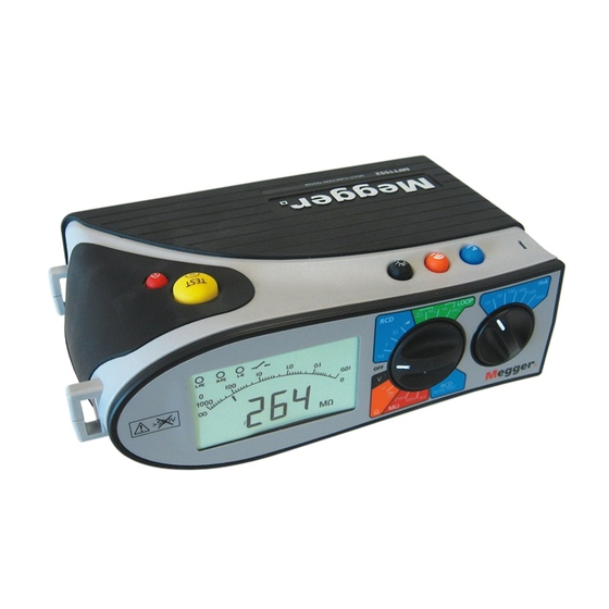
MFT1500/2, MFT1552 and MFT1553 Series
Multifunction Tester
USER MANUAL
Table of
Contents
Previous
Page
Next
Page
1
2
3
4
5
Advertisement
Table of Contents
Need help?
Do you have a question about the MFT1500/2 and is the answer not in the manual?
Ask a question
Questions and answers
Related Manuals for Megger MFT1500/2
Multimeter Megger MFT1500/2 Quick Start Manual
Multifunction tester (9 pages)
Multimeter Megger MFT1553 Series User Manual
Multifunction tester (32 pages)
Multimeter Megger M8035 User Manual
(79 pages)
Multimeter Megger M8035 User Manual
(63 pages)
Multimeter Megger AVO410 User Manual
(70 pages)
Multimeter Megger AVO410 User Manual
Digital multimeter (16 pages)
Multimeter Megger BMM80 Series User Manual
Insulation multimeters (12 pages)
Multimeter Megger BMM2000 Series User Manual
Insulation multimeters (14 pages)
Multimeter Megger AVO300 Series User Manual
(53 pages)
Multimeter Megger AVO 830 User Manual
True rms digital multi-meter (48 pages)
Multimeter Megger AVO 850 User Manual
Trms industrial logging digital multimeter with colour display (61 pages)
Multimeter Megger BM8 User Manual
Multi-voltage insulation tester (4 pages)
Multimeter Megger PMM-1 User Manual
Power multimeter (70 pages)
Multimeter Megger AVO 415 User Manual
Trms digital multimeter with vfd measurement (52 pages)
This manual is also suitable for:
Mft1552
Mft1553 series
Table of Contents
Save PDF
Print
Rename the bookmark
Delete bookmark?
Delete from my manuals?
Login
Sign In
OR
Sign in with Facebook
Sign in with Google
Upload manual
Upload from disk
Upload from URL


Need help?
Do you have a question about the MFT1500/2 and is the answer not in the manual?
Questions and answers