Advertisement
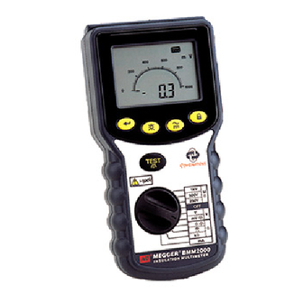
M BMM2000 Series
•
Safety Warnings and Precautions must be read and
understood before the instrument is used. They must be
observed during use.
•
The circuit under test must be de-energised and isolated
before connections are made except for voltage measurement.
•
Circuit connections must not be touched during a test.
•
After insulation tests, capacitive circuits must be allowed to
discharge before disconnecting the test leads.
•
The Live Circuit Warning and Automatic Discharge are additional
safety features and should not be regarded as a substitute for
normal safe working practice.
•
Replacement fuses must be of the correct type and rating.
Failure to fit the correctly rated fuse will result in damage to the
instrument in the event of an overload.
•
Test leads, including crocodile clips, must be in good order,
clean and have no broken or cracked insulation.
•
Ensure that hands remain behind guards of probes/clips when
testing.
•
U.K. Safety Authorities recommend the use of fused test leads
when measuring voltage on high energy systems.
THE INSTRUMENTS MUST ONLY BE USED BY
SUITABLY TRAINED AND COMPETENT PERSONS
Users of this equipment and/or their employers are reminded that
Health and Safety Legislation require them to carry out valid risk
assessments of all electrical work so as to identify potential
sources of electrical danger and risk of electrical injury such as
from inadvertent short circuits. Where the assessments show that
the risk is significant then the use of fused test leads constructed
in accordance with the HSE guidance note GS38 'Electrical Test
Equipment for use by Electricians' should be used.
Symbols used on the instruments are:
>500V
Insulation Multimeters
User Guide
SAFETY WARNINGS
Caution, risk of electric shock.
Caution, refer to User Guide.
Equipment protected throughout by
Double Insulation (Class II).
Equipment complies with current EU Directives.
Equipment must not be connected
to installations >500V.
NOTE
Advertisement
Table of Contents

Related Manuals for Megger BMM2000 Series


Summary of Contents for Megger BMM2000 Series
- Page 1 M BMM2000 Series Insulation Multimeters User Guide SAFETY WARNINGS • Safety Warnings and Precautions must be read and understood before the instrument is used. They must be observed during use. • The circuit under test must be de-energised and isolated before connections are made except for voltage measurement.
-
Page 2: General Description
Series instruments, eg temperature or humidity measurement. A customised connector on the top of the instrument enables the optional Megger SP1 Switched Probe to be used for two handed probe operation. The 250V, 500V and 1000V ranges can be used to test... - Page 3 Live Circuit Warning When more than 25V (10V on 10V insulation range) is applied to the terminals in the insulation ranges, the instrument defaults to a voltmeter and gives an audible warning if a test is attempted.On all other switch positions except OFF/V when approx 10V is applied the default voltmeter will be activated.
- Page 4 10 minutes divided by the resistance value after 1 minute. The test can be run at any voltage. More detailed information on PI Testing and value assessment can be found in Megger Limited publications listed in the Accessories page. Automatic Discharge When the TEST button is released after an insulation test (or re-pressed if ltb feature is enabled), a 200kΩ...
- Page 5 Continuity Testing (Ω) (See fig.2) The continuity tests are activated when the probes make contact of less than a few kΩ. The tests apply a constant current and measure the resulting volt drop across the circuit under test. The test operates without the need to press the TEST button.
- Page 6 Display: Audible: <5Ω continuous bleep <3kΩ short bleep >3kΩ no bleep Resistance Tests (kΩ) This is a low voltage (5V) low current (25µA) test for sensitive electronic equipment. It operates in the same way as the continuity ranges. 1. Set the selector switch to kΩ. 2.
- Page 7 Zeroing of d.c. mV (no a.c. mV zero facility) To zero the d.c. mV range, short the leads together in the d.c. mV position, wait for the reading to settle and then press the TEST button. Up to 9,9mV can be zeroed on the d.c. mV range.
- Page 8 SP1 acts as a remote test button to operate the instrument and as a ‘Low’ probe. This simplifies instrument control and two- handed probing. The SP1 is suitable for use with Megger insulation test instruments up to 1kV output test voltage.
-
Page 9: Specification
SPECIFICATION (All quoted accuracies are at +20°C.) Insulation Ranges Nominal Test Voltage (d.c.): BMM2080: 50V, 100V, 250V, 500V, 1000V BMM2000: 250V, 500V, 1000V BMM2000ESD: 10V, 100V, 500V Test voltage accuracy: 1000V, 500V, 250V, 100V, 50V, +15% maximum on open circuit. 10V, ±10% maximum on open circuit. - Page 10 Zero offset at probe tips: 0,10Ω typical Lead resistance zeroing: Up to 9,99Ω Noise rejection: 1V rms 50/60Hz Buzzer: Operates at less than 5Ω (approx). Resistance Measuring Range: 0,01kΩ to 9,99MΩ (0 to 100MΩ on analogue scale) Accuracy: ±3% ± 2digits Open circuit voltage: 5V ±1V Short circuit current:...
- Page 11 then calculate the measurement range. This is the range of measurement over which the error in service is less than 30% of the reading. Digital instruments are affected by the number of digits error – for example a value 0,10Ω measured with the continuity range may give a display in the range 0,07Ω...
-
Page 12: Power Supply
Complies with the following parts of EN61557, Electrical safety in low voltage systems up to 1000V a.c. and 1500V d.c. – Equipment for testing, measuring or monitoring of protective measures:- Part 1 – General requirements Part 2 – Insulation resistance Part 4 –... -
Page 13: Repair And Warranty
Approved Repair Companies A number of independent instrument repair companies have been approved for repair work on most Megger instruments, using genuine Megger spare parts. Consult the Appointed Distributor / Agent regarding spare parts, repair facilities and advice on the best course of action to take. - Page 14 F +33 (1) 34.61.23.77 This instrument is manufactured in the United Kingdom. The company reserves the right to change the specification or design without prior notice. Megger is a registered trademark Part No. 6172-492 V10 Printed in England 1003 www.megger.com...
Need help?
Do you have a question about the BMM2000 Series and is the answer not in the manual?
Questions and answers