HP Compaq CQ58 Maintenance And Service Manual
Hide thumbs
Also See for Compaq CQ58:
- Maintenance and service manual (104 pages) ,
- Maintenance and service manual (124 pages) ,
- Maintenance and service manual (94 pages)
Table of Contents
Advertisement
Quick Links
Advertisement
Table of Contents

Related Manuals for HP Compaq CQ58


Summary of Contents for HP Compaq CQ58
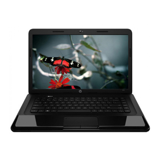
- Page 1 HP 2000 Notebook PC Compaq CQ58 Notebook PC Maintenance and Service Guide...
- Page 2 The information contained herein is subject to change without notice. The only warranties for HP products and services are set forth in the express warranty statements accompanying such products and services. Nothing herein should be construed as constituting an additional warranty.
- Page 3 Safety warning notice WARNING! To reduce the possibility of heat-related injuries or of overheating the device, do not place the device directly on your lap or obstruct the device air vents. Use the device only on a hard, flat surface. Do not allow another hard surface, such as an adjoining optional printer, or a soft surface, such as pillows or rugs or clothing, to block airflow.
- Page 4 Safety warning notice ENWW...
-
Page 5: Table Of Contents
Table of contents 1 Product description ............................1 2 External component identification ......................... 5 Right side ................................5 Left side ................................. 6 Front ..................................7 Display ................................... 8 Top ..................................9 TouchPad ............................. 9 Lights ..............................10 Buttons .............................. 11 Keys .............................. - Page 6 Packaging and transporting guidelines ............34 Component replacement procedures ......................... 36 Service tag and PCID label ......................... 36 Service tag ........................36 PCID label ........................37 Computer feet ........................... 38 Battery ............................... 39 Display subcomponents (bezel, webcam, panel) ................40 WLAN module ............................
- Page 7 Recovering using HP Recovery Manager ..................112 What you need to know ....................112 Using the HP Recovery partition to recover (select models only) ....... 112 Using HP Recovery media to recover ................113 Changing the computer boot order ................113 Removing the HP Recovery partition .....................
- Page 8 viii ENWW...
-
Page 9: Product Description
Product description Category Description AMD models Intel models Product name Compaq CQ58 Notebook PC √ HP 2000 Notebook PC √ √ Processors AMD processors A6-5200, 2.0-GHz processor (1600-MHz memory speed, quad core, 25 W) √ A4-5000, 1.5-GHz processor (1600-MHz memory speed, dual core, 15 W) √... - Page 10 Category Description AMD models Intel models B980 2.40-GHz processor (2.0-MB L3 cache, dual core, 35 W) √ B970 2.30-GHz processor (1333-MHz memory speed, 2.0-MB L3 cache, √ dual core, 35 W) B960 2.20-GHz processor (2.0-MB L3 cache, dual core, 35 W) √...
- Page 11 √ √ Altec Lansing speakers √ √ Supports Microsoft Premium requirements √ √ HP TrueVision HD webcam (fixed, no tilt with activity LED, 1280×720 by 30 √ √ frames per second Ethernet Integrated 10/100 network interface card (NIC) √ √...
- Page 12 Taps enabled by default √ √ Power AC adapter requirements 65-W RC V HP Smart AC adapter with localized cable plug support (3-wire √ √ plug with ground pin, supports 3-pin DC connector) Support for the following batteries: √ √...
-
Page 13: External Component Identification
External component identification Right side Component Description Optical drive Reads an optical disc. NOTE: On select models, the optical drive also writes to an optical disc. ● Optical drive light Green: The optical drive is being accessed. ● Off: The optical drive is idle. Optical drive eject button Releases the disc tray. -
Page 14: Left Side
Left side Component Description External monitor port Connects an external VGA monitor or projector. Vent Enables airflow to cool internal components. NOTE: The computer fan starts up automatically to cool internal components and prevent overheating. It is normal for the internal fan to cycle on and off during routine operation. -
Page 15: Front
Component Description ● Hard drive light Blinking white: The hard drive is being accessed. ● (10) Power light White: The computer is on. ● Blinking white: The computer is in the Sleep state, which is an energy-saving mode. The computer shuts off power to the display and other unneeded components. -
Page 16: Display
Display Component Description Internal display switch Turns off the display and initiates Sleep if the display is closed while the power is on. NOTE: The internal display switch is not visible from the outside of the computer. Internal microphone Records sound. Webcam Records video, captures still photographs, and allows video conferences and online chat by means of streaming video. -
Page 17: Top
TouchPad Component Description TouchPad on/off button Turns the TouchPad on or off. ● TouchPad light Amber: The TouchPad is enabled. ● Off: The TouchPad is disabled. TouchPad zone Moves the on-screen pointer and selects or activates items on the screen. Left TouchPad button Functions like the left button on an external mouse. -
Page 18: Lights
Lights Component Description Caps lock light White: Caps lock is on, which switches the keys to all capital letters. Off: Caps lock is off. ● Power light White: The computer is on. ● Blinking white: The computer is in the Sleep state, which is an energy-saving mode. -
Page 19: Buttons
Buttons Component Description ● Power button When the computer is off, press the button to turn on the computer. ● When the computer is in the Sleep state, press the button briefly to exit Sleep. ● When the computer is in Hibernation, press the button down briefly to exit Hibernation. -
Page 20: Keys
Keys Component Description Displays system information when pressed in combination with key. Displays system information when pressed in combination with key. Windows 8 logo key Windows 8: Returns you to the Start screen from an open app or the Desktop. NOTE: Pressing the Windows logo key again will return you to the previous screen. -
Page 21: Bottom
Bottom Component Description Battery bay Holds the battery. Vents (3) Enable airflow to cool internal components. NOTE: The computer fan starts up automatically to cool internal components and prevent overheating. It is normal for the internal fan to cycle on and off during routine operation. Battery release latch Releases the battery from the battery bay. - Page 22 Component Description Wireless and memory module Contains the wireless and memory modules. compartment CAUTION: To prevent an unresponsive system, replace the wireless module only with a wireless module authorized for use in the computer by the governmental agency that regulates wireless devices in your country or region.
-
Page 23: Illustrated Parts Catalog
Illustrated parts catalog Computer major components ENWW Computer major components... - Page 24 Power button board (includes cable) 689686-001 Top cover (includes TouchPad): For use with Compaq models 689696-001 For use with blue HP models 689694-001 For use with black HP models 689695-001 Speakers (includes left and right speakers and cable) 689693-001...
- Page 25 Item Component Spare part number For use only with models with an AMD C-70 processor ● Models without Windows 8 713023-001 ● Models with Windows 8 Standard 713023-501 For use only with models with an AMD C-60 processor ● Models without Windows 8 693564-001 ●...
- Page 26 Item Component Spare part number (15) Processor (includes replacement thermal materials): NOTE: Only valid on models with Intel processors. On AMD models, the processor comes with the system board and cannot be removed. Intel Core i5 processors (3.0-MB L3 cache, dual core, 35 W): ●...
- Page 27 Item Component Spare part number 4 GB 641369-001 2 GB 652972-001 (18) Hard drive (2.5-in, SATA; does not include hard drive cable or bracket): NOTE: The hard drive cable and bracket are included in the Hard Drive Hardware Kit, spare part number 685089-001. 750-GB, 5400-rpm 634250-001 640-GB, 5400-rpm...
-
Page 28: Display Assembly Subcomponents
Display assembly subcomponents Item Component Spare part number Display bezel: For use with Compaq models 689676-001 For use with HP models 689675-001 Webcam/microphone module 685112-001 703461-001 Chapter 3 Illustrated parts catalog ENWW... - Page 29 Display cable (includes display panel cable and webcam/microphone cable) 689677-001 Antennas (includes wireless antenna cables and transceivers) 689670-001 Display enclosure: For use with Compaq models 689673-001 For use with black HP models 689672-001 For use with blue HP models 689671-001 ENWW Display assembly subcomponents...
-
Page 30: Mass Storage Devices
Mass storage devices Item Component Spare part number Hard drive (2.5-in, SATA; does not include hard drive cable or bracket): NOTE: The hard drive cable and bracket are included in the Hard Drive Hardware Kit, spare part number 685089-001. 750-GB, 5400-rpm 634250-001 640-GB, 5400-rpm 669300-001... -
Page 31: Plastics Kit
Plastics kit Item Component Spare part number Plastics Kit, includes: 689689-001 Hard drive compartment cover (includes one captive screw, secured by a C-clip) Memory module/wireless module compartment cover (includes one captive screw, secured by a C-clip) ENWW Plastics kit... -
Page 32: Miscellaneous Parts
Miscellaneous parts Component Spare part number HP Smart AC adapter (65-W RC V) For use in all countries and regions except for India and China 693711-001 For use in India and China 693710-001 Power cord (3-pin, black, 1.83-m) For use in Australia... -
Page 33: Sequential Part Number Listing
Sequential part number listing Spare part number Description 449137-001 RTC battery 490371-001 Power cord for use in North America (3-pin, black, 1.83-m) 490371-011 Power cord for use in Australia (3-pin, black, 1.83-m) 490371-021 Power cord for use in Europe, the Middle East, and Africa (3-pin, black, 1.83-m) 490371-031 Power cord for use in the United Kingdom and Singapore (3-pin, black, 1.83-m) 490371-111... - Page 34 Fan/heat sink assembly for use only with models with an AMD processor (includes replacement thermal materials) 689670-001 Antennas (includes wireless antenna cables and transceivers) 689671-001 Display enclosure for use with blue HP models 689672-001 Display enclosure for use with black HP models 689673-001 Display enclosure for use with Compaq models...
- Page 35 Screw Kit 689693-001 Speakers (includes left and right speakers and cable) 689694-001 Top cover for use with blue HP models (includes TouchPad) 689695-001 Top cover for use with black HP models (includes TouchPad) 689696-001 Top cover for use with Compaq models (includes TouchPad) 690019-001 Atheros AR9565 802.11bgn 1x1 WiFi + BT4.0 combo Adapter...
- Page 36 Spare part number Description 698694-051 Keyboard for use in France (includes keyboard cable) 698694-061 Keyboard for use in Italy (includes keyboard cable) 698694-071 Keyboard for use in Spain (includes keyboard cable) 698694-131 Keyboard for use in Portugal (includes keyboard cable) 698694-141 Keyboard for use in Turkey (includes keyboard cable) 698694-151...
- Page 37 Spare part number Description 713163-001 Intel Core i3 3130M, 2.60-GHz processor (3.0-MB L3 cache, dual core, 35 W) 713164-001 Intel Pentium 2030M, 2.50-GHz processor (2.0-MB L3 cache, dual core, 35 W) 713165-001 Intel Core i3 2348M, 2.30-GHz processor (3.0-MB L3 cache, dual core, 35 W) 715890-001 System board for use only with models without Windows 8 and with an AMD E1-1500 processor (includes replacement thermal materials)
- Page 38 Chapter 3 Illustrated parts catalog ENWW...
-
Page 39: Removal And Replacement Procedures
Removal and replacement procedures Preliminary replacement requirements Tools required You will need the following tools to complete the removal and replacement procedures: ● Flat-bladed screwdriver ● Magnetic screwdriver ● Phillips P0 and P1 screwdrivers Service considerations The following sections include some of the considerations that you must keep in mind during disassembly and assembly procedures. -
Page 40: Drive Handling
Drive handling CAUTION: Drives are fragile components that must be handled with care. To prevent damage to the computer, damage to a drive, or loss of information, observe these precautions: Before removing or inserting a hard drive, shut down the computer. If you are unsure whether the computer is off or in Hibernation, turn the computer on, and then shut it down through the operating system. - Page 41 Typical electrostatic voltage levels Relative humidity Event Walking across carpet 35,000 V 15,000 V 7,500 V Walking across vinyl floor 12,000 V 5,000 V 3,000 V Motions of bench worker 6,000 V 800 V 400 V Removing DIPS from plastic tube 2,000 V 700 V 400 V...
-
Page 42: Packaging And Transporting Guidelines
Packaging and transporting guidelines Follow these grounding guidelines when packaging and transporting equipment: ● To avoid hand contact, transport products in static-safe tubes, bags, or boxes. ● Protect ESD-sensitive parts and assemblies with conductive or approved containers or packaging. ● Keep ESD-sensitive parts in their containers until the parts arrive at static-free workstations. - Page 43 Equipment guidelines Grounding equipment must include either a wrist strap or a foot strap at a grounded workstation. ● When seated, wear a wrist strap connected to a grounded system. Wrist straps are flexible straps with a minimum of one megohm ±10% resistance in the ground cords. To provide proper ground, wear a strap snugly against the skin at all times.
-
Page 44: Component Replacement Procedures
Component replacement procedures This chapter provides removal and replacement procedures. Make special note of each screw's size and location during removal and replacement. Service tag and PCID label Service tag When ordering parts or requesting information, provide the computer serial number and model description provided on the service tag. -
Page 45: Pcid Label
PCID label The PCID label provides the information required to properly reset the notebook firmware (BIOS) back to factory shipped specifications when replacing the system board. The label may have a different number of characters depending on the operating system on the computer. Windows 8 models Non-Windows 8 models ENWW... -
Page 46: Computer Feet
Computer feet Description Spare part number Rubber computer feet 691221-001 The computer feet are adhesive-backed rubber pads. There are 4 rubber feet that attach to the base enclosure in the locations illustrated below. Chapter 4 Removal and replacement procedures ENWW... -
Page 47: Battery
Battery Description Spare part number 6-cell, 55-Whr, 2.55-Ah Li-ion battery 593554-001 6-cell, 47-Whr, 2.20-Ah Li-ion battery 593553-001 Before disassembling the computer, follow these steps: Shut down the computer. If you are unsure whether the computer is off or in Hibernation, turn the computer on, and then shut it down through the operating system. -
Page 48: Display Subcomponents (Bezel, Webcam, Panel)
75 for more information about removing the display assembly in its entirety. Description Spare part number Display bezel for use on HP models (includes Mylar screw covers) 689675-001 Display bezel for use on Compaq models (includes Mylar screw covers) 689676-001 Raw display panel, 39.6-cm (15.6-inch), HD, LED, BrightView... - Page 49 Flex and disengage the inside edges of the bottom (3), left and right sides (4), and top (5) of the bezel. Open the computer and position it on its side with the back and bottom facing you. ENWW Component replacement procedures...
- Page 50 Use a tool to pry to bottom of the bezel from the display (1), and then remove the bezel from the display (2). Chapter 4 Removal and replacement procedures ENWW...
- Page 51 To remove the webcam/microphone module: Remove the two broadhead Phillips PM2.5×2.5 screws (1) that secure the display panel and hinges to the enclosure, and then tilt the display panel (2) away from the enclosure as far as possible. ENWW Component replacement procedures...
- Page 52 Disconnect the module cable from the module. Chapter 4 Removal and replacement procedures ENWW...
- Page 53 Remove the webcam/microphone module. (The module is attached to the display enclosure with double-sided tape.) ENWW Component replacement procedures...
- Page 54 To remove the display panel: Remove the four Phillips PM2.0×3.0 screws (1) that secure the display hinges to the display panel, and then tilt the display panel down (2) until it rests on the computer. Release the adhesive strip (1) that secures the display panel cable to the display panel, and then disconnect the display panel cable (2) from the display panel.
- Page 55 Release the webcam/microphone module cable that is secured to the back of the display panel with adhesive material, and then remove the display panel (3). Reverse this procedure to reassemble and install the display bezel, webcam/microphone module, and display panel. ENWW Component replacement procedures...
-
Page 56: Wlan Module
WLAN module Description Spare part number Atheros AR9485 802.11b/g/n 1x1 WiFi Adapter 675794-001 Atheros 9485GN 802.11b/g/n 1x1 WiFi and 3012 Bluetooth 4.0 Combo Adapter 655795-001 Broadcom 4313GN 802.11b/g/n 1x1 WiFi and 20702 Bluetooth 4.0 Combo Adapter 657325-001 Ralink WLAN Ralink Ripple3 RT5390F_802.11 b/g/n 1x1 PCIe HMC 670691-001 Atheros AR9565 802.11bgn 1x1 WiFi + BT4.0 combo Adapter 690019-001... - Page 57 To remove the WLAN module: Loosen the memory module/wireless module compartment cover screw (1), and then lift up on the tab (2) and remove the cover (3). The memory module/wireless module compartment cover is available in the Plastics Kit. For more information about the Plastics Kit, see Plastics kit on page Disconnect the WLAN antenna cables (1) from the terminals on the WLAN module.
- Page 58 Reverse this procedure to install the WLAN module. Chapter 4 Removal and replacement procedures ENWW...
-
Page 59: Memory Module
To remove a memory module: NOTE: In Compaq CQ58 models, if only one DIMM is installed, it must be installed in the bottom slot Flip up the Mylar sheet protecting the memory module compartment. Spread the retaining tabs (1) on each side of the memory module slot to release the memory module. - Page 60 Remove the memory module (2) by pulling it away from the slot at an angle. Reverse this procedure to install a memory module. Chapter 4 Removal and replacement procedures ENWW...
-
Page 61: Hard Drive
Hard drive NOTE: The hard drive spare part kit does not include the hard drive cable or bracket. The hard drive cable and bracket are included in the Hard Drive Hardware Kit. Description Spare part number 750-GB, 5400-rpm 634250-001 640-GB, 5400-rpm 669300-001 500-GB, 5400-rpm 669299-001... - Page 62 Lift the hard drive (2) out of the hard drive bay. Turn over the hard drive, then disconnect the hard drive cable (1) from the hard drive. Pull the sides of the hard drive bracket (2) out and away from the hard drive. Remove the hard drive (3) from the bracket.
-
Page 63: Rtc Battery
RTC battery Description Spare part number RTC battery 449137-001 Before removing the RTC battery, follow these steps: Shut down the computer. If you are unsure whether the computer is off or in Hibernation, turn the computer on, and then shut it down through the operating system. Disconnect all external devices connected to the computer. -
Page 64: Optical Drive
Optical drive NOTE: The optical drive spare part kit includes the rear optical drive bracket but does not include the optical drive cable or cable bracket. The optical drive cable and cable bracket are included in the optical drive cable kit. See Optical drive cable on page 88 for more information about the optical drive cable and cable bracket. - Page 65 Remove the two Phillips PM2.0×3.0 screws (1) that secure the bracket to the optical drive. Remove the optical drive bracket (2). Reverse this procedure to reassemble and install the optical drive. ENWW Component replacement procedures...
-
Page 66: Keyboard
Keyboard NOTE: The keyboard spare part kit includes a keyboard cable. Description Spare part number Keyboard for use with French Canada 698694-xx1 NOTE: For a detailed list of keyboard spare parts, see Sequential part number listing on page Before removing the keyboard, follow these steps: Shut down the computer. - Page 67 Insert a screwdriver or similar small tool into the keyboard release hole (2), and then press on the back of the keyboard until the keyboard disengages from the computer. Turn the computer right-side up with the front toward you. Lift the rear edge of the keyboard (1), and then swing the keyboard up and forward (2) until it rests upside down on the palm rest.
- Page 68 Remove the keyboard (3). Reverse this procedure to install the keyboard. Chapter 4 Removal and replacement procedures ENWW...
-
Page 69: Top Cover
TouchPad button board, see TouchPad button board on page Description Spare part number Top cover for use in blue HP models (includes Touchpad) 689694-001 Top cover for use in black HP models (includes Touchpad) 689695-001 Top cover for use in Compaq models (includes Touchpad) - Page 70 Remove the eight Phillips PM2.5×6.0 screws that secure the top cover to the computer. Remove the four Phillips PM2.0×2.5 screws that secure the top cover to the computer. Chapter 4 Removal and replacement procedures ENWW...
- Page 71 Remove the Phillips PM2.0×3.0 screw from the optical drive bay (1) and the three Phillips PM2.5×4.0 screws from the hard drive bay (2) that secure the top cover to the computer. Turn the computer right-side up with the front toward you, and then open the computer. Release the ZIF connectors to the power button board cable (1) and the TouchPad button board cable (2), and then disconnect the cables from the system board.
- Page 72 Remove the eight Phillips PM2.0×4.0 screws that secure the top cover to the computer. Lift the rear edge of the top cover (1) until the left and right sides disengage from the base enclosure. Remove the top cover (2). Reverse this procedure to install the top cover. Chapter 4 Removal and replacement procedures ENWW...
-
Page 73: Power Button Board
Power button board Description Spare part number Power button board (includes cable) 689686-001 Before removing the power button board, follow these steps: Shut down the computer. If you are unsure whether the computer is off or in Hibernation, turn the computer on, and then shut it down through the operating system. - Page 74 Reverse this procedure to install the power button board and cable. Chapter 4 Removal and replacement procedures ENWW...
-
Page 75: Touchpad Button Board
TouchPad button board Description Spare part number TouchPad button board (includes bracket and cables) 689688-001 Before removing the TouchPad button board, follow these steps: Shut down the computer. If you are unsure whether the computer is off or in Hibernation, turn the computer on, and then shut it down through the operating system. - Page 76 Remove the TouchPad button board cable (4) from the opening in the top cover, and then remove the TouchPad button board (5). Reverse this procedure to install the TouchPad button board. Chapter 4 Removal and replacement procedures ENWW...
-
Page 77: Speakers
Speakers Description Spare part number Speakers (includes left and right speakers and cable) 689693-001 Before removing the speakers, follow these steps: Shut down the computer. If you are unsure whether the computer is off or in Hibernation, turn the computer on, and then shut it down through the operating system. Disconnect all external devices connected to the computer. - Page 78 Remove the speakers (4). Reverse this procedure to install the speakers. Chapter 4 Removal and replacement procedures ENWW...
-
Page 79: Usb Board
USB board Description Spare part number USB board (includes cable) 689687-001 Before removing the USB board, follow these steps: Shut down the computer. If you are unsure whether the computer is off or in Hibernation, turn the computer on, and then shut it down through the operating system. Disconnect all external devices connected to the computer. - Page 80 Remove the USB board (3). Reverse this procedure to install the USB board. Chapter 4 Removal and replacement procedures ENWW...
-
Page 81: Power Connector Cable
Power connector cable Description Spare part number Power connector cable 689678-001 Before removing the power connector cable, follow these steps: Shut down the computer. If you are unsure whether the computer is off or in Hibernation, turn the computer on, and then shut it down through the operating system. Disconnect all external devices connected to the computer. - Page 82 Remove the power connector cable (3). Reverse this procedure to install the power connector cable. Chapter 4 Removal and replacement procedures ENWW...
-
Page 83: Display Assembly
Display cable (includes display panel cable and webcam/microphone cable; also includes Mylar screw 689677-001 covers) Display enclosure for use in blue HP models (includes Mylar screw covers) 689671-001 Display enclosure for use in black HP models (includes Mylar screw covers) - Page 84 Release the wireless antenna cables from the clips (2) built into the base enclosure. NOTE: Models may have either one or two antennas installed. CAUTION: Support the display assembly when removing the following screws. Failure to support the display assembly can result in damage to the display assembly and other computer components. Remove the five Phillips PM2.5×7.0 screws (1) that secure the display assembly to the computer.
- Page 85 Remove the display assembly (2). NOTE: Models may have either one or two antennas installed. If it is necessary to replace any of the display assembly subcomponents: To remove the display bezel: Remove the two Mylar screw covers (1) and the two Phillips PM2.5×4.0 screws (2) that secure the display bezel to the display assembly.
- Page 86 Remove the display bezel (6). To remove the webcam/microphone module: Remove the two broadhead Phillips PM2.5×2.5 screws (1) that secure the display panel to the enclosure. Tilt the display panel (2) up. Chapter 4 Removal and replacement procedures ENWW...
- Page 87 Disconnect the module cable (3) from the module. ENWW Component replacement procedures...
- Page 88 Remove the webcam/microphone module. (The module is attached to the display enclosure with double-sided tape.) Chapter 4 Removal and replacement procedures ENWW...
- Page 89 To remove the hinge covers: Remove the two Phillips PM2.5×4.0 screws (1) that secure the top hinge covers to the display enclosure, and then remove the top hinge covers (2). Remove the two Phillips PM2.0×3.0 screws (1) that secure the side hinge covers to the display enclosure, and then remove the side hinge covers (2).
- Page 90 To remove the display panel, cable, and hinges: Remove the four Phillips PM2.5×4.0 screws (1) that secure the display panel to the enclosure, and then remove the display panel (2) from the enclosure. On the back of the display panel, release the adhesive strip (1) that secures the display panel cable to the display panel, and then disconnect (2) and remove (3) the cable.
- Page 91 Remove the display hinges (2). To remove the wireless antenna cables and transceivers: Release the wireless antenna transceivers (1) from the display enclosure. (The wireless antenna transceivers are attached to the display enclosure with double-sided tape.) Release the wireless antenna cables from the clips (2) built into the display enclosure. Remove the wireless antenna cables and transceivers (3).
-
Page 92: System Board
System board NOTE: On models with Intel processors, you can remove the processor from the system board. The processor is included with the system board in AMD models and cannot be removed. NOTE: The system board spare part kit includes replacement thermal materials (including a thermal pad). Description Spare part number System board for use only with computer models equipped with an AMD A6-5200 processor... - Page 93 Description Spare part number ● For use in models with Windows 8 Standard 715890-501 System board for use only with computer models equipped with an AMD E1-1200 processor ● For use in models without Windows 8 688278-001 ● For use in models with Windows 8 Standard 688278-501 System board for use only with computer models equipped with an Intel Core i5 or i3 processor and a graphics subsystem with UMA video memory (RCTO system board for use in Brazil and India only)
- Page 94 NOTE: When replacing the system board, be sure that the following components are removed from the defective system board and installed on the replacement system board: ● Memory module (see Memory module on page ● RTC battery (see RTC battery on page ●...
- Page 95 Tilt the system board up to the left slightly (2), and then remove the system board (3). NOTE: A thermal pad services a component on the bottom of the system board. Replacement thermal material is included with all system board spare part kits. Reverse this procedure to install the system board.
-
Page 96: Optical Drive Cable
Optical drive cable Description Spare part number Optical drive cable (includes cable bracket) 685084-001 Before removing the optical drive cable, follow these steps: Shut down the computer. If you are unsure whether the computer is off or in Hibernation, turn the computer on, and then shut it down through the operating system. - Page 97 Release the optical drive cable from the clips (4) built into the base enclosure. Reverse this procedure to install the optical drive cable. ENWW Component replacement procedures...
-
Page 98: Fan/Heat Sink Assembly
Fan/heat sink assembly NOTE: The fan/heat sink assembly spare part kit includes replacement thermal materials. Description Spare part number Fan/heat sink assembly for use only with computer models equipped with an AMD processor 688281-001 Fan/heat sink assembly for use only with computer models equipped with an Intel processor and a 685086-001 graphics subsystem with UMA video memory NOTE:... - Page 99 Remove the Phillips PM2.0×3.0 screw (3) that secures the fan to the system board. Remove the fan/heat sink assembly (4). NOTE: Due to the adhesive quality of the thermal material located between the heat sink and system board components, it may be necessary to move the heat sink from side to side to detach it. NOTE: The following illustration shows the fan/heat sink assembly removal process on a computer model equipped with an AMD processor.
- Page 100 NOTE: The following illustration shows the fan/heat sink assembly removal process on a computer model equipped with an Intel processor and a graphics subsystem with UMA memory. Chapter 4 Removal and replacement procedures ENWW...
- Page 101 The thermal material must be thoroughly cleaned from the surfaces of the heat sink and the system board components each time the heat sink is removed. Replacement thermal materials are included with the fan/ heat sink assembly, processor, and system board spare part kits. NOTE: The following illustration shows the replacement thermal material locations on a computer model equipped with an AMD processor.
- Page 102 ● Thermal paste is used on the processor (1) and the heat sink section (2) that services it NOTE: The following illustration shows the replacement thermal material locations on a computer model equipped with an Intel processor and a graphics subsystem with discrete memory. ●...
- Page 103 ● Thermal paste is used on the processor (1) and the heat sink section (2) that services it Reverse this procedure to reassemble and install the fan/heat sink assembly. ENWW Component replacement procedures...
-
Page 104: Processor
Processor NOTE: This section applies only to computer models equipped with an Intel processor. AMD processors come soldered to the system board and cannot be removed or replaced. NOTE: On models with Intel processors you can remove the processor from the system board. The processor is included with the system board in AMD models and cannot be removed. - Page 105 Disconnect the power from the computer by first unplugging the power cord from the AC outlet and then unplugging the AC adapter from the computer. Remove the battery (see Battery on page 39), and then remove the following components: ● WLAN module (see WLAN module on page ●...
- Page 106 Lift the processor (3) straight up, and then remove it. NOTE: The gold triangle (4) on the processor must be aligned with the triangle icon embossed on the processor socket when you install the processor. Reverse this procedure to install the processor. Chapter 4 Removal and replacement procedures ENWW...
-
Page 107: Using Setup Utility (Bios) And System Diagnostics
Updating the BIOS Updated versions of the BIOS may be available on the HP website. Most BIOS updates on the HP website are packaged in compressed files called SoftPaqs. Some download packages contain a file named Readme.txt, which contains information regarding installing and troubleshooting the file. -
Page 108: Downloading A Bios Update
Do not insert, remove, connect, or disconnect any device, cable, or cord. From the Start screen, select the HP Support Assistant app. Click Updates and tune-ups, and then click Check for HP updates now. Follow the on-screen instructions. At the download area, follow these steps: Identify the most recent BIOS update and compare it to the BIOS version currently installed on your computer. -
Page 109: Using System Diagnostics
Using System Diagnostics System Diagnostics allows you to run diagnostic tests to determine if the computer hardware is functioning properly. To start System Diagnostics: Turn on or restart the computer, quickly press esc, and then press f2. Click the diagnostic test you want to run, and then follow the on-screen instructions. NOTE: If you need to stop a diagnostic test while it is running, press esc. - Page 110 102 Chapter 5 Using Setup Utility (BIOS) and System Diagnostics ENWW...
-
Page 111: Specifications
Specifications Computer specifications Metric U.S. Dimensions Depth 23.1 cm 9.09 in Width 34.2 cm 13.46 in Height (front to back) 3.00 to 3.55 cm 1.18 to 1.40 in Weight 2.19 kg 4.84 lb Input power Operating voltage and current 18.5 V dc @ 3.5 A or 19.5 V dc @ 3.33 A – 65 W 19 V dc @ 4.74 A or 19.5 V dc @ 4.62 A –... -
Page 112: 39.6-Cm (15.6-In), Hd Display Specifications
39.6-cm (15.6-in), HD display specifications Metric U.S. Active diagonal size 39.6-cm 15.6-in Resolution 1366x768 (HD) Active area 344.232x193.536 Surface treatment Anti-glare or BrightView Contrast ratio 300:1 (typical) – Anti-glare 500:1 – BrightView Response time 8 ms Brightness 200 nits (typical) Viewing angle Backlight Luminance uniformity @ 13 points... -
Page 113: Hard Drive Specifications
Hard drive specifications 750-GB* 640-GB* 500-GB* 320-GB* Dimensions Height 7.0 mm 7.0 mm 7.0 mm 7.0 mm Length 100.4 mm 100.4 mm 100.4 mm 100.4 mm Width 69.9 mm 69.9 mm 69.9 mm 69.9 mm Weight 115 g 98.8 g 95.0 g 98.8 g Interface type... - Page 114 106 Chapter 6 Specifications ENWW...
-
Page 115: Backing Up, Restoring, And Recovering
Backing up, restoring, and recovering Your computer includes tools provided by HP and the operating system to help you safeguard your information and retrieve it if you ever need to. These tools will help you return your computer to a proper working state or even back to the original factory state, all with simple steps. -
Page 116: Creating Recovery Media And Backups
Recovery after a system failure is only as good as your most recent backup. After you successfully set up the computer, create HP Recovery media. This step creates a backup of the HP Recovery partition on the computer. The backup can be used to reinstall the original operating system in cases where the hard drive is corrupted or has been replaced. - Page 117 DVD recovery media, you can use an external optical drive (purchased separately) to create recovery discs, or you can obtain recovery discs for your computer from the HP website. For U.S. support, go to http://www.hp.com/go/contactHP. For worldwide support, go to http://welcome.hp.com/country/us/en/wwcontact_us.html.
-
Page 118: Restore And Recovery
Recovering using HP Recovery Manager on page 112. ● If you have replaced the hard drive, you can use the Factory Reset option of HP Recovery media to restore the factory image to the replacement drive. For more information, see Recovering using HP Recovery Manager on page 112. -
Page 119: Using Windows Refresh For Quick And Easy Recovery
Using Windows Refresh for quick and easy recovery When your computer is not working properly and you need to regain system stability, the Windows Refresh option allows you to start fresh and keep what is important to you. IMPORTANT: Refresh removes any traditional applications that were not originally installed on the system at the factory. -
Page 120: Recovering Using Hp Recovery Manager
To use the Factory Reset option, you must use HP Recovery media. ● If the HP Recovery media do not work, you can obtain recovery media for your system from the HP website. For U.S. support, go to http://www.hp.com/go/contactHP. For worldwide support, go to http://welcome.hp.com/country/us/en/wwcontact_us.html. -
Page 121: Using Hp Recovery Media To Recover
Using HP Recovery media to recover You can use HP Recovery media to recover the original system. This method can be used if your system does not have an HP Recovery partition or if the hard drive is not working properly. - Page 122 114 Chapter 7 Backing up, restoring, and recovering ENWW...
-
Page 123: Power Cord Set Requirements
Power cord set requirements The wide-range input feature of the computer permits it to operate from any line voltage from 100 to 120 volts ac, or from 220 to 240 volts ac. The 3-conductor power cord set included with the computer meets the requirements for use in the country or region where the equipment is purchased. -
Page 124: Requirements For Specific Countries And Regions
Requirements for specific countries and regions Country/region Accredited agency Applicable note number Argentina IRAM Australia Austria Belgium CEBEC Brazil ABNT Canada Chile Denmark DEMKO Finland FIMKO France Germany India Israel Italy Japan The Netherlands KEMA New Zealand SANZ Norway NEMKO The People's Republic of China Saudi Arabia SASO... - Page 125 Country/region Accredited agency Applicable note number The United States The flexible cord must be Type HO5VV-F, 3-conductor, 0.75mm conductor size. Power cord set fittings (appliance coupler and wall plug) must bear the certification mark of the agency responsible for evaluation in the country or region where it will be used.
- Page 126 118 Chapter 8 Power cord set requirements ENWW...
-
Page 127: Recycling
When you remove these components, handle them carefully. NOTE: Materials Disposal. This HP product contains mercury in the backlight in the display assembly that might require special handling at end-of-life. Disposal of mercury may be regulated because of environmental considerations. For disposal or recycling information, contact your local authorities, or see the Electronic Industries Alliance (EIA) Web site at http://www.eiai.org. - Page 128 Perform the following steps: Remove all screw covers (1) and screws (2) that secure the display bezel to the display assembly. Lift up and out on the left and right inside edges (1) and the top and bottom inside edges (2) of the display bezel until the bezel disengages from the display assembly.
- Page 129 Disconnect all display panel cables (1) from the display inverter and remove the inverter (2). Remove all screws (1) that secure the display panel assembly to the display enclosure. Remove the display panel assembly (2) from the display enclosure. Turn the display panel assembly upside down. Remove all screws that secure the display panel frame to the display panel.
- Page 130 Remove the display panel frame (2) from the display panel. Remove the screws (1) that secure the backlight cover to the display panel. Lift the top edge of the backlight cover (2) and swing it outward. Remove the backlight cover. Turn the display panel right-side up.
- Page 131 Remove the backlight cables (1) from the clip (2) in the display panel. Turn the display panel upside down. Remove the backlight frame from the display panel. WARNING! The backlight contains mercury. Exercise caution when removing and handling the backlight to avoid damaging this component and causing exposure to the mercury. Remove the backlight from the backlight frame.
- Page 132 Disconnect the display cable (1) from the LCD panel. Remove the screws (2) that secure the LCD panel to the display rear panel. Release the LCD panel (3) from the display rear panel. Release the tape (4) that secures the LCD panel to the display rear panel. Remove the LCD panel.
-
Page 133: Index
110 determining version 99 Digital Media Slot fan/heat sink assembly downloading an update 100 identifying 6 illustrated 16 updating 99 display assembly removing 90 boot order illustrated 16 spare part number 26 changing HP Recovery Manager removing 40, 75... - Page 134 82 locating 38 spare part number 27 mass storage devices spare part number 27 HP Recovery Manager 112 illustrated 22 fn key correcting boot problems 113 precautions 32 identifying 12 starting 112 memory module HP Recovery media illustrated 18...
- Page 135 Digital Media 6 illustrated 17 system 112 security cable 5 removing 73 USB flash drive 113 speakers spare part number 27 using HP Recovery media 109 identifying 7 power cord recovery media illustrated 16 requirements for all countries creating 108 removing 69...
- Page 136 system restore point Windows creating 108 backup 108 restoring 110 File History 108, 110 Refresh 110, 111 reinstall 110, 111 thermal pad remove everything and reinstall spare part number 25 option 111 tools required 31 reset 111 top cover restoring files 110 illustrated 16 system restore point 108, 110 removing 61...
Need help?
Do you have a question about the Compaq CQ58 and is the answer not in the manual?
Questions and answers
i need to make a bios recovery USB? For CQ58 -200EI Compaq, HP no longer supports it on their support site where can i download from.