Table of Contents
Advertisement
RETURN TO MAIN INDEX
RETURN TO MAIN MENU
SVM201-A
July, 2010
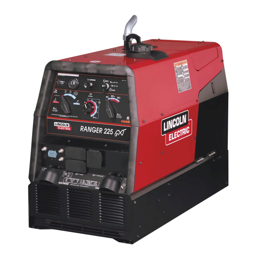
RANGER 225 GXT
11522
For use with machine code number:
Safety Depends on You
Lincoln arc welding and cutting
equipment is designed and built
with safety in mind.
However,
your
overall
safety
can
be
increased by proper installation
. . . and thoughtful operation on
your part.
DO NOT INSTALL,
OPERATE OR REPAIR THIS
EQUIPMENT WITHOUT READ-
ING THIS MANUAL AND THE
SAFETY PRECAUTIONS CON-
TAINED THROUGHOUT.
And,
most importantly, think before you
act and be careful.
SERVICE MANUAL
Copyright © Lincoln Global Inc.
• World's Leader in Welding and Cutting Products •
• Sales and Service through Subsidiaries and Distributors Worldwide •
Cleveland, Ohio 44117-1199 U.S.A. TEL: 888.935.3877 FAX: 216.486.1751 WEB SITE: www.lincolnelectric.com
Advertisement
Chapters
Table of Contents
Troubleshooting

Related Manuals for Lincoln Electric RANGER 225 GXT


Summary of Contents for Lincoln Electric RANGER 225 GXT
-
Page 1: Service Manual
RETURN TO MAIN INDEX RETURN TO MAIN MENU SVM201-A July, 2010 RANGER 225 GXT 11522 For use with machine code number: Safety Depends on You Lincoln arc welding and cutting equipment is designed and built with safety in mind. However, your overall... -
Page 2: California Proposition 65 Warnings
Miami, Florida 33135 or CSA Standard W117.2-1974. A Free copy of “Arc Welding Safety” booklet E205 is available from the Lincoln Electric Company, 22801 St. Clair Avenue, Cleveland, Ohio 44117-1199. BE SURE THAT ALL INSTALLATION, OPERATION, MAINTENANCE AND REPAIR PROCEDURES ARE PERFORMED ONLY BY QUALIFIED INDIVIDUALS. -
Page 3: Electric Shock Can Kill
ELECTRIC SHOCK can kill. 3.a. The electrode and work (or ground) circuits are electrically “hot” when the welder is on. Do not touch these “hot” parts with your bare skin or wet clothing. Wear dry, hole-free gloves to insulate hands. - Page 4 WELDING and CUTTING SPARKS can cause fire or explosion. 6.a. Remove fire hazards from the welding area.If this is not possible, cover them to prevent the welding sparks from starting a fire. Remember that welding sparks and hot materials from welding can easily go through small cracks and openings to adjacent areas.
- Page 5 PRÉCAUTIONS DE SÛRETÉ Pour votre propre protection lire et observer toutes les instructions et les précautions de sûreté specifiques qui parraissent dans ce manuel aussi bien que les précautions de sûreté générales suiv- antes: Sûreté Pour Soudage A L’Arc 1. Protegez-vous contre la secousse électrique: a.
- Page 6 SAFETY Electromagnetic Compatibility (EMC) Conformance Introduction Installation and Use Assessment of Area RANGER® 225 GXT...
- Page 7 SAFETY Electromagnetic Compatibility (EMC) Methods of Reducing Emissions Mains Supply Maintenance of the Welding Equipment Welding Cables Equipotential Bonding Earthing of the Workpiece Screening and Shielding RANGER® 225 GXT...
- Page 8 - MASTER TABLE OF CONTENTS FOR ALL SECTIONS - RETURN TO MAIN MENU Page Safety ................i-iv Installation .
-
Page 9: Table Of Contents
Angle of Operation ...A-5 High Altitude Operation ...A-5 Location/Ventilation ...A-6 Connection of Wire Feeders ...A-6 Additional Safety Precautions ...A-6 Welder Operation ...A-6 Auxiliary Power ...A-7 120V Duplex Receptacles...A-7 Motor Starting...A-7 Electrical Devices used w/Ranger® 225 GXT ...A-8 Auxiliary Power While Welding ...A-9 Stand-by Power Connections...A-9... -
Page 10: Installation
Aluminum Alloy with Cast Iron Liners, Electronic Ignition RATED OUTPUT @ 104°F (40°C)- WELDER DC Constant Current 210A / 25V / 100% DC Constant Voltage 200A / 20V / 100% RATED OUTPUT @ 104°F (40°C)- GENERATOR RECEPTACLES AND CIRCUIT BREAKERS... -
Page 11: Safety Precautions
To prevent dangerous electric shock, other equip- ment to which this engine driven welder supplies power must: • be grounded to the frame of the welder using a grounded type plug, or be double insulated. Do not ground the machine to a pipe that carries explosive or combustible material. -
Page 12: Pre-Operation Service
Use caution as the electrolyte is a strong acid that can burn skin and damage eyes. ----------------------------------------------------------------------- This welder is shipped with the negative battery cable disconnected. Make sure that the Engine Switch is in the “STOP” position and attach the disconnected cable securely to the negative battery terminal before attempting to operate the machine. -
Page 13: Welding Output Cables
Listed below are copper cable sizes recommended for the rated current and duty cycle. Lengths stipulated are the distance from the welder to work and back to the welder again. Cable sizes are increased for greater lengths primarily for the purpose of minimizing cable voltage drop. -
Page 14: Location/Ventilation
Also, locate the welder so that engine exhaust fumes are properly vented to an outside area. -
Page 15: Welder Operation
WELDER OPERATION WELDER OUTPUT • Maximum Open Circuit Voltage at 3700 RPM is 80 Volts RMS. • Duty Cycle is the percentage of time the load is being applied in a 10 minute period. For example, a 60% duty cycle represents 6 minutes of load and 4 minutes of no load in a 10 minute period. - Page 16 Capacitive/Inductive Computers, high resolution TV sets, The Lincoln Electric Company is not responsible for any damage to electrical components improperly connected to the RANGER® 225 GXT. INSTALLATION TABLE lll complicated electrical equipment.
-
Page 17: Auxiliary Power While Welding
AUXILIARY POWER WHILE WELDING Simultaneous welding and power loads are permitted by following Table I. The permissible currents shown assume that current is being drawn from either the 120V or 240V supply (not both at the same time). Also, the “Output Control” is set at “10” for maximum auxil- iary power. -
Page 18: Connection Of Ranger® 225 Gxt To Premises Wiring
INSTALLATION A-10 A-10 Figure 1 CONNECTION OF RANGER® 225 GXT TO PREMISES WIRING WARNING Connection of RANGER® 225 GXT to premises wiring must be done by a licensed electrician and must comply with the National Electrical Code and all other applicable electrical codes. RANGER®... - Page 19 TABLE OF CONTENTS - OPERATION SECTION Operation...Section B Safety Precautions ...B-2 General Description ...B-2 Welder Controls ...B-2 Engine Switch ...B-2 Range Switch ...B-3 Controls Dial ...B-3 Fuel Consumption ...B-3 Engine Operation ...B-4 Before Starting the Engine ...B-4 Starting the Engine ...B-4 Stopping the Engine ...B-4...
-
Page 20: Engine Switch
• Insulate yourself from work and ground • Always wear dry insulating gloves. • Always operate the welder with the hinged door closed and the side panels in place. • Read carefully the Safety Precautions page before operating this machine. Always follow... -
Page 21: Polarity Switch
“ RANGE” SWITCH The “Range” switch is used to select one of four amperage ranges with generous overlap for Stick/TIG welding, or one Wire Feed welding range. Process Range Setting STICK/TIG 90 Max. (constant current) 145 Max. (3 range settings) 210DC/225AC MAX 120 to 210(DC) 225(AC) WIRE FEED... -
Page 22: Starting/Shutdown Instructions
STARTING/SHUTDOWN INSTRUCTIONS STARTING THE ENGINE WARNING • Do not touch electrically live parts of electrode with skin or wet clothing. • Keep flammable material away. • Insulate yourself from work and ground. Wear eye, ear, and body protection. • Keep your head out of the fumes. •... -
Page 23: Welding Process
WELDING PROCESS For any electrodes the procedures should be kept with- in the rating of the machine. For electrode information see the appropriate Lincoln publication. STICK (CONSTANT CURRENT) WELDING Connect welding cables to the "TO WORK” and "ELECTRODE” studs. Start the engine. Set the "Polarity”... - Page 24 SUMMARY OF WELDING PROCESSES CONTROL CABLE PROCESS USED STICK WIRE FEED, LN-25 WITH INTERNAL CONTACTOR TIG, TIG MODULE WITH WITH CONTACTOR KIT CONTROL CABLE, & AMPTROL WIRE FEED, LN-15 ACROSS the ARC (has internal contactor) When welding with MIG wire instead of self-shielded core wire, weld starts can be improved by setting the idle mode to “HIGH”.
- Page 25 TABLE OF CONTENTS - ACCESSORIES SECTION Accessories...Section C Optional Equipment ...C-2 Recommended Equipment ...C-3 Stick...C-3 TIG...C-3 Wirefeed ...C-3 Plasma Cutting ...C-3 RANGER® 225 GXT...
-
Page 26: Optional Equipment
OPTIONAL EQUIPMENT K2635-1 SMALL TWO-WHEEL ROAD TRAILER WITH DUO-HITCH-For heavy-duty road, off-road, plant and yard use. Includes pivoting jack stand, safety chains, and 13" wheels. Overall width 60". Stiff .120" welded rectangu- lar steel tube frame construction is phosphate etched and powder coat painted for superior rust and corro- sion resistance. -
Page 27: Recommended Equipment
RECOMMENDED EQUIPMENT STICK K704 Accessory Kit- (400 AMP Capacity) which includes: • Electrode Holder & Cable • Work Clamp & Cable • Headshield K875 Accessory Kit- (150 AMP Capacity) WIRE FEED K449 LN-25 - Includes internal contactor for across the arc operation (no control cable). Provides “cold” elec- trode until gun trigger is pressed. - Page 28 NOTES RANGER® 225 GXT...
-
Page 29: Maintenance
TABLE OF CONTENTS - MAINTENANCE SECTION Maintenance ...Section D Service Instructions...D-2 Safety Precautions...D-3 Routine Maintenance ...D-3 Engine Maintenance...D-3 Change the Oil ...D-3 Engine Oil Refill Capacities...D-3 Change the Oil Filter ...D-4 Engine Adjustments...D-5 Slip Rings ...D-5 Hardware & Battery ...D-5 Major Component Locations ...D-6 -MAINTENANCE- RANGER®... - Page 30 MAINTENANCE RANGER® 225 GXT...
-
Page 31: Engine Oil Change
SAFETY PRECAUTIONS WARNING Have qualified personnel do the maintenance work. Turn the engine off before working inside the machine. In some cases, it may be necessary to remove safety guards to perform required maintenance. Remove guards only when necessary and replace them when the mainte- nance requiring their removal is complete. -
Page 32: Oil Filter Change
Use 4-stroke motor oil that meets or exceeds the requirements for API service classification SG or SH. Always check the API SERVICE label on the oil con- tainer to be sure it includes the letters SG or SH. SAE 10W-30 is recommended for general, all-temper- ature use, -5 F to 104 F (-20 C to 40 C). -
Page 33: Engine Adjustments
• CONNECTING A BATTERY CHARG- ER - Remove battery from welder by disconnecting negative cable first, then positive cable and battery clamp. When reinstalling, connect negative cable last. Keep well venti- lated. - Page 34 1. Case Front Assembly 2. Control Panel Assembly 3. Base/Fuel Tank/Battery Assembly 4. Engine Assembly 5. Blower Baffle Assembly 6. Stator/Rotor Assembly 7. Covers & Case Back Assembly FIGURE D.1 - MAJOR COMPONENT LOCATION MAINTENANCE RANGER® 225 GXT...
- Page 35 TABLE OF CONTENTS-THEORY OF OPERATION SECTION Theory of Operation ...Section E Battery, Starter, Engine, Excitation, Rotor, Stator and Idler Solenoid...E-2 Rotor Field Feedback and Auxiliary Power ...E-3 Weld Winding, Reactor, and Range Switch...E-4 Output Bridge, Choke, Polarity Switch, and Output Terminals ...E-5 FIGURE E.1 RANGER®...
-
Page 36: Theory Of Operation
THEORY OF OPERATION FIGURE E.2 - BATTERY, STARTER, ENGINE, ROTOR, STATOR AND IDLER SOLENOID P R E S S U R E C A P A C I T O R B A T T E R Y M E T E R S O L E N O I D P R I N T E D C I R C U I T S W I T C H... - Page 37 THEORY OF OPERATION FIGURE E.3 – ROTOR FIELD FEEDBACK AND AUXILIARY POWER H O U R S L I P I D L E R S T A R T E R F I E L D B O A R D A L T E R N A T O R S W I T C H R O T O R...
-
Page 38: Range Switch
THEORY OF OPERATION FIGURE E.4 – WELD WINDING, REACTOR AND RANGE SWITCH I D L E R C A P A C I T O R S T A R T E R R O T O R B O A R D A L T E R N A T O R S O L E N O I D M E C H A N I C A L... - Page 39 THEORY OF OPERATION FIGURE E.5 – OUTPUT BRIDGE, CHOKE, POLARITY SWITCH AND OUTPUT TERMINALS B O A R D P R I N T E D C I R C U I T A U X 2 3 0 V O L T 1 1 5 V O L T C O N T R O L O U P U T...
- Page 40 NOTES RANGER® 225 GXT...
- Page 41 TABLE OF CONTENTS - TROUBLESHOOTING AND REPAIR Troubleshooting & Repair Section ...Section F How to Use Troubleshooting Guide ...F-2 PC Board Troubleshooting Procedures ...F-3 Troubleshooting Guide ...F4 - F-14 Test Procedures Rotor Voltage Test ...F-15 Rotor Resistance Test ...F-17 Auxiliary and Field Winding Test ...F-21 Output Rectifier Bridge Test ...F-25 Charging Circuit Test ...F-27 Engine Throttle Adjustment Test...F-29...
-
Page 42: How To Use Troubleshooting Guide
TROUBLESHOOTING AND REPAIR HOW TO USE TROUBLESHOOTING GUIDE Service and Repair should only be performed by Lincoln Electric Factory Trained Personnel. Unauthorized repairs performed on this equipment may result in danger to the technician and machine operator and will invalidate your factory warranty. For your safety and to avoid Electrical Shock, please observe all safety notes and precautions detailed throughout this manual. -
Page 43: Pc Board Troubleshooting Procedures
- If the PC board uses protective shorting jumpers, don’t remove them until installation is complete. - If you return a PC board to The Lincoln Electric Company for credit, it must be in the static-shielding bag. This will prevent further damage and allow prop- er failure analysis. - Page 44 The engine operates normally. If for any reason you do not understand the test procedures or are unable to perform the tests/repairs safely, contact the Lincoln Electric Service Department for technical troubleshooting assistance before you proceed. Call 1-888-935-3877. POSSIBLE AREAS OF...
- Page 45 230VAC) is normal. The engine operates normally. If for any reason you do not understand the test procedures or are unable to perform the tests/repairs safely, contact the Lincoln Electric Service Department for technical troubleshooting assistance before you proceed. Call 1-888-935-3877. POSSIBLE AREAS OF...
- Page 46 If for any reason you do not understand the test procedures or are unable to perform the tests/repairs safely, contact the Lincoln Electric Service Department for technical troubleshooting assistance before you proceed. Call 1-888-935-3877. POSSIBLE AREAS OF...
- Page 47 If for any reason you do not understand the test procedures or are unable to perform the tests/repairs safely, contact the Lincoln Electric Service Department for technical troubleshooting assistance before you proceed. Call 1-888-935-3877. POSSIBLE AREAS OF...
- Page 48 If for any reason you do not understand the test procedures or are unable to perform the tests/repairs safely, contact the Lincoln Electric Service Department for technical troubleshooting assistance before you proceed. Call 1-888-935-3877. POSSIBLE AREAS OF...
- Page 49 If for any reason you do not understand the test procedures or are unable to perform the tests/repairs safely, contact the Lincoln Electric Service Department for technical troubleshooting assistance before you proceed. Call 1-888-935-3877. POSSIBLE AREAS OF...
- Page 50 If for any reason you do not understand the test procedures or are unable to perform the tests/repairs safely, contact the Lincoln Electric Service Department for technical troubleshooting assistance before you proceed. Call 1-888-935-3877. POSSIBLE AREAS OF...
- Page 51 Switch (S3) is in “HIGH” position. If for any reason you do not understand the test procedures or are unable to perform the tests/repairs safely, contact the Lincoln Electric Service Department for technical troubleshooting assistance before you proceed. Call 1-888-935-3877.
- Page 52 If for any reason you do not understand the test procedures or are unable to perform the tests/repairs safely, contact the Lincoln Electric Service Department for technical troubleshooting assistance before you proceed. Call 1-888-935-3877. POSSIBLE AREAS OF...
- Page 53 S3 is switched to “RUN” position. If for any reason you do not understand the test procedures or are unable to perform the tests/repairs safely, contact the Lincoln Electric Service Department for technical troubleshooting assistance before you proceed. Call 1-888-935-3877.
- Page 54 Auxiliary power is functioning normally. If for any reason you do not understand the test procedures or are unable to perform the tests/repairs safely, contact the Lincoln Electric Service Department for technical troubleshooting assistance before you proceed. Call 1-888-935-3877. POSSIBLE AREAS OF...
-
Page 55: Test Description
F-15 ROTOR VOLTAGE TEST PROCEDURE Service and repair should be performed only by Lincoln Electric factory trained personnel. Unauthorized repairs performed on this equipment may result in danger to the technician or machine operator and will invalidate your factory warranty. For your safety and to avoid electrical shock, please observe all safety notes and precautions detailed throughout this manual. -
Page 56: Test Procedures
TROUBLESHOOTING AND REPAIR F-16 ROTOR VOLTAGE TEST (continued) FIGURE F.1 - SLIP RINGS AND BRUSHES L e a d 2 1 9 L e a d 2 0 0 A S l i p R i n g s B r u s h e s Brushes TEST PROCEDURE 1. -
Page 57: Rotor Resistance Test
F-17 ROTOR RESISTANCE TEST Service and repair should be performed only by Lincoln Electric factory trained personnel. Unauthorized repairs performed on this equipment may result in danger to the technician or machine operator and will invalidate your factory warranty. For your safety and to avoid electrical shock, please observe all safety notes and precautions detailed throughout this manual. - Page 58 TROUBLESHOOTING AND REPAIR F-18 ROTOR RESISTANCE TEST (continued) L e a d 2 0 0 A L e a d 2 1 9 TEST PROCEDURE 1. With the 5/16” nut driver, remove the 6 sheet metal screws from the case top. 2.
- Page 59 TROUBLESHOOTING AND REPAIR F-19 ROTOR RESISTANCE TEST (continued) 13. Measure the resistance to ground. A. Set the ohmmeter on the high scale (X100,000). B. Place one probe on either of the slip rings. Place the other probe on any good, unpainted ground.
- Page 60 NOTES F-20 F-20 RANGER® 225 GXT...
-
Page 61: Auxiliary And Field Winding Test
F-21 AUXILIARY AND FIELD WINDING TEST Service and repair should be performed only by Lincoln Electric factory trained personnel. Unauthorized repairs performed on this equipment may result in danger to the technician or machine operator and will invalidate your factory warranty. For your safety and to avoid electrical shock, please observe all safety notes and precautions detailed throughout this manual. - Page 62 TROUBLESHOOTING AND REPAIR F-22 AUXILIARY AND FIELD WINDING TEST (continued) FIGURE F.3 – LOCATION OF LEADS #3 AND #5 L e a d # 3 L e a d # 5 R e c e p t a c l e 1 1 5 V F r o n t M a c h i n e...
- Page 63 TROUBLESHOOTING AND REPAIR F-23 AUXILIARY AND FIELD WINDING TEST (continued) To test the field winding: 1. Remove the fuel cap and lift bail rubber gasket. With the 5/16” nut driver, remove the case top and left side; then reinstall the fuel cap. 2.
- Page 64 NOTES F-24 F-24 RANGER® 225 GXT...
-
Page 65: Output Rectifier Bridge Test
F-25 OUTPUT RECTIFIER BRIDGE TEST Service and repair should be performed only by Lincoln Electric factory trained personnel. Unauthorized repairs performed on this equipment may result in danger to the technician or machine operator and will invalidate your factory warranty. For your safety and to avoid electrical shock, please observe all safety notes and precautions detailed throughout this manual. - Page 66 TROUBLESHOOTING AND REPAIR F-26 OUTPUT RECTIFIER BRIDGE TEST (continued) FIGURE F.4 – LOCATION OF OUTPUT RECTIFIER LEADS ( + ) ( - ) T O S 1 ( + ) ( - ) 2 5 4 C H O K E L 1 T O T O S 2 T O P O L A R I T Y S W I T C H...
-
Page 67: Charging Circuit Test
TROUBLESHOOTING AND REPAIR F-27 Service and repair should be performed only by Lincoln Electric factory trained personnel. Unauthorized repairs performed on this equipment may result in danger to the technician or machine operator and will invalidate your factory warranty. For your safety and to avoid electrical shock, please observe all safety notes and precautions detailed throughout this manual. -
Page 68: Location Of Voltage Regulator
TROUBLESHOOTING AND REPAIR F-28 CHARGING CIRCUIT TEST (continued) FIGURE F.5 – LOCATION OF VOLTAGE REGULATOR LEADS A C L e a d A C L e a d D C L e a d R e g u l a t o r V o l t a g e TEST PROCEDURE 1. -
Page 69: Engine Throttle Adjustment Test
F-29 ENGINE THROTTLE ADJUSTMENT TEST Service and repair should be performed only by Lincoln Electric factory trained personnel. Unauthorized repairs performed on this equipment may result in danger to the technician or machine operator and will invalidate your factory warranty. For your safety and to avoid electrical shock, please observe all safety notes and precautions detailed throughout this manual. - Page 70 TROUBLESHOOTING AND REPAIR F-30 ENGINE THROTTLE ADJUSTMENT TEST (continued) FIGURE F.6 – BLOWER PADDLE MARKED FOR STROBE-TACH METHOD B l o w e r P a d d l e Blower Paddle TEST PROCEDURE This test can be conducted by any one of four methods.
- Page 71 TROUBLESHOOTING AND REPAIR F-31 ENGINE THROTTLE ADJUSTMENT TEST (continued) FIGURE F.7 HIGH IDLE ADJUSTMENT NUT C a b l e C h o k e A d j u s t m e n t N u t l i n k a g e 3 / 8 "...
- Page 72 TROUBLESHOOTING AND REPAIR F-32 ENGINE THROTTLE ADJUSTMENT TEST (continued) Oscilloscope Method: 1. Connect the oscilloscope to the 115 VAC receptacle, according to the manufacturer’s instructions. At 3700 RPM, the waveform should exhibit a period of 16.2 milliseconds. At 2400 RPM, the waveform should exhibit a period of 25.0 milliseconds.
-
Page 73: Normal Open Circuit Voltage Waveform (115 Vac Supply
TROUBLESHOOTING AND REPAIR F-33 NORMAL OPEN CIRCUIT VOLTAGE WAVEFORM (115 VAC SUPPLY) HIGH IDLE – NO LOAD – OUTPUT CONTROL AT MAXIMUM 16.2 ms 50 volts This is the typical AC output voltage generated from a properly operating machine. Note that each vertical divi- sion represents 50 volts and that each horizontal division represents 5 mil- liseconds in time. -
Page 74: Typical Dc Weld Output Waveform (Cv Mode)
TROUBLESHOOTING AND REPAIR F-34 TYPICAL DC WELD OUTPUT WAVEFORM (CV MODE) MACHINE LOADED TO 200 AMPS AT 20 VDC MACHINE LOADED 20 volts This is the typical CV output voltage generated from a properly operating machine. Note that each vertical divi- sion represents 20 volts and that each horizontal division represents 5 mil- liseconds in time. -
Page 75: Typical Dc Weld Output Waveform (Cc Mode)
TROUBLESHOOTING AND REPAIR F-35 TYPICAL DC WELD OUTPUT WAVEFORM (CC MODE) MACHINE LOADED TO 200 AMPS AT 26 VDC MACHINE LOADED 20 volts This is the typical DC output voltage generated from a properly operating machine. Note that each vertical divi- sion represents 20 volts and that each horizontal division represents 5 mil- liseconds in time. -
Page 76: Typical Ac Weld Output Waveform
TROUBLESHOOTING AND REPAIR F-36 TYPICAL AC WELD OUTPUT WAVEFORM MACHINE LOADED TO 225 AMPS AT 25 VDC MACHINE LOADED 20 volts This is the typical AC output voltage generated from a properly operating machine. Note that each vertical divi- sion represents 20 volts and that each horizontal division represents 5 mil- liseconds in time. -
Page 77: Abnormal Open Circuit Weld Voltage Waveform (Cv Mode)
TROUBLESHOOTING AND REPAIR F-37 ABNORMAL OPEN CIRCUIT WELD VOLTAGE WAVEFORM (CV MODE) HIGH IDLE - NO LOAD - OUTPUT CONTROL AT MAXIMUM ONE OUTPUT DIODE NOT FUNCTIONING 20 volts This is NOT the typical CV output volt- age waveform. One output diode is not functioning. -
Page 78: Abnormal Open Circuit Dc Weld Voltage Waveform
TROUBLESHOOTING AND REPAIR F-38 ABNORMAL OPEN CIRCUIT DC WELD VOLTAGE WAVEFORM HIGH IDLE - NO LOAD - OUTPUT CONTROL AT MAXIMUM ONE OUTPUT DIODE NOT FUNCTIONING 50 volts This is NOT the typical DC (+) output voltage waveform. One output diode is not functioning. Note the “gap” in the waveform. -
Page 79: Normal Open Circuit Weld Voltage Waveform (Cv Mode)
TROUBLESHOOTING AND REPAIR F-39 NORMAL OPEN CIRCUIT WELD VOLTAGE WAVEFORM (CV MODE) HIGH IDLE - NO LOAD - OUTPUT CONTROL AT MAXIMUM 20 volts This is the typical CV output voltage generated from a properly operating machine. Note that each vertical divi- sion represents 20 volts and that each horizontal division represents 5 mil- liseconds in time. - Page 80 TROUBLESHOOTING AND REPAIR F-40 NORMAL OPEN CIRCUIT DC WELD VOLTAGE WAVEFORM (CC MODE) HIGH IDLE - NO LOAD - OUTPUT CONTROL AT MAXIMUM 50 volts This is the typical DC output voltage generated from a properly operating machine. Note that each vertical divi- sion represents 50 volts and that each horizontal division represents 5 mil- liseconds in time.
-
Page 81: Troubleshooting And Repair
TROUBLESHOOTING AND REPAIR F-41 NORMAL OPEN CIRCUIT AC WELD VOLTAGE WAVEFORM HIGH IDLE - NO LOAD - OUTPUT CONTROL AT MAXIMUM 50 volts This is the typical auxiliary output volt- age generated from a properly operat- ing machine. Note that each vertical division represents 50 volts and that each horizontal division represents 5 milliseconds in time. - Page 82 NOTES F-42 F-42 RANGER® 225 GXT...
-
Page 83: Brush Removal And Replacement Procedure
F-43 BRUSH REMOVAL AND REPLACEMENT PROCEDURE Service and repair should be performed only by Lincoln Electric factory trained personnel. Unauthorized repairs performed on this equipment may result in danger to the technician or machine operator and will invalidate your factory warranty. For your safety and to avoid electrical shock, please observe all safety notes and precautions detailed throughout this manual. - Page 84 TROUBLESHOOTING AND REPAIR F-44 BRUSH REMOVAL AND REPLACEMENT PROCEDURE (continued) PROCEDURE 1. Remove the spark plug wires. 2. With the 5/16” nut driver, remove the 6 sheet metal screws from the case top. 3. Remove the rubber gasket (cover seal) from the lift bail.
-
Page 85: Slip Rings
TROUBLESHOOTING AND REPAIR F-45 BRUSH REMOVAL AND REPLACEMENT PROCEDURE (continued) 7 / 1 6 " B r u s h A s s e m b l y B r a c k e t B o l t s 7/16"... - Page 86 NOTES F-46 F-46 RANGER® 225 GXT...
-
Page 87: Printed Circuit Board Removal And Replacement Procedure
PRINTED CIRCUIT BOARD REMOVAL AND REPLACEMENT PROCEDURE Service and repair should be performed only by Lincoln Electric factory trained personnel. Unauthorized repairs performed on this equipment may result in danger to the technician or machine operator and will invalidate your factory warranty. For your safety and to avoid electrical shock, please observe all safety notes and precautions detailed throughout this manual. -
Page 88: Printed Circuit Board Removal
TROUBLESHOOTING AND REPAIR F-48 PRINTED CIRCUIT BOARD REMOVAL AND REPLACEMENT PROCEDURE (continued) 1 2 P i n P l u g 1 / 4 " Q . C . T a b s 4 P i n P l u g 4 S e l f T a p p i n g S c r e w s ( a t c o r n e r s ) 4 Pin Plug PROCEDURE... - Page 89 TROUBLESHOOTING AND REPAIR F-49 PRINTED CIRCUIT BOARD REMOVAL AND REPLACEMENT PROCEDURE (continued) CAUTION Be sure to follow the recommended static-free methods for handling printed circuit boards. Failure to do so can result in permanent damage to the equipment. 12. With the 1/4” phillips head screw driver, remove four self tapping screws holding the printed circuit board.
- Page 90 NOTES F-50 F-50 RANGER® 225 GXT...
-
Page 91: Output Rectifier Bridge Removal And Replacement Procedure
OUTPUT RECTIFIER BRIDGE REMOVAL AND REPLACEMENT PROCEDURE Service and repair should be performed only by Lincoln Electric factory trained personnel. Unauthorized repairs performed on this equipment may result in danger to the technician or machine operator and will invalidate your factory warranty. For your safety and to avoid electrical shock, please observe all safety notes and precautions detailed throughout this manual. - Page 92 TROUBLESHOOTING AND REPAIR F-52 OUTPUT RECTIFIER BRIDGE REMOVAL AND REPLACEMENT PROCEDURE (continued) ( + ) ( - ) L 1 T O T O S 1 2 5 4 T O S 2 ( + ) ( - ) C H O K E T O P O L A R I T Y S W I T C H ( - ) ( + )
- Page 93 TROUBLESHOOTING AND REPAIR F-53 OUTPUT RECTIFIER BRIDGE REMOVAL AND REPLACEMENT PROCEDURE (continued) 12. Using a 13mm wrench, remove the two mounting nuts. Note the placement of the nylon insulators. 13. Remove the rectifier assembly by pulling it away from the blower baffle. 14.
- Page 94 NOTES F-54 F-54 RANGER® 225 GXT...
-
Page 95: Engine/Rotor Removal And Replacement Procedure
F-55 ENGINE/ROTOR REMOVAL AND REPLACEMENT PROCEDURE Service and repair should be performed only by Lincoln Electric factory trained personnel. Unauthorized repairs performed on this equipment may result in danger to the technician or machine operator and will invalidate your factory warranty. For your safety and to avoid electrical shock, please observe all safety notes and precautions detailed throughout this manual. - Page 96 TROUBLESHOOTING AND REPAIR F-56 REMOVAL AND REPLACEMENT PROCEDURE (continued) FIGURE F.12 – ENGINE/ROTOR COMPONENT LOCATIONS 1 A 1 A 5 A 5 A 1 C 1 C 5 B 5 B 1 B 1 B 1 0 B 1 0 C 1 0 B 1 0 A 1 0 A...
- Page 97 TROUBLESHOOTING AND REPAIR F-57 REMOVAL AND REPLACEMENT PROCEDURE (continued) PROCEDURE 1. Refer to Figure F.12 for component locations. 2. Remove the engine spark plug wires. 3. With the 5/16” nut driver, remove the 6 sheet metal screws from the case top. 4.
- Page 98 Pull out the thru- bolt. 3. Install the appropriate long thru-bolt (two are provided) supplied with Lincoln Electric Rotor Removal Kit S20788. The slot head must face out. Screw in the bolt with the slot head screw driver until the bolt bottoms out on the engine crankshaft, about 3/4”.
-
Page 99: Reassembly Procedure
TROUBLESHOOTING AND REPAIR F-59 REMOVAL AND REPLACEMENT PROCEDURE (continued) REASSEMBLY PROCEDURE NOTE: Lincoln Electric recommends that a new bearing (Lincoln part #M9300-85) be installed when you replace the rotor and blower assembly. 1. Clean the tapered engine crankshaft. Slide the rotor onto the shaft. -
Page 100: Retest After Repair
Output values of each receptacle can vary within the range shown but must be within 2 volts of each other. RETEST AFTER REPAIR ENGINE OUTPUT No Load RPM 2300-2500 3700-3750 WELDER DC OUTPUT Open Circuit Volts 65 - 72 WELDER AC OUTPUT Open Circuit... - Page 101 TABLE OF CONTENTS - DIAGRAM SECTION Electrical Diagrams ..............G-1 Wiring Diagram Complete Machine (M21812) .
-
Page 102: Electrical Diagrams
NOTE: This diagram is for reference only. It may not be accurate for all machines covered by this manual. The wiring diagram specific to your code is pasted inside one of the enclosure panels of your machine. ElEcTrical DiaGramS RANGER 225 GXT POLARITY SWITCH S2... -
Page 103: Schematic - Complete Machine (L13820
SCALE: CONTROL: Error: N o refer ence EQUIPMENT TYPE: RANGER 225 GXT UNLESS OTHERWISE SPECIFIED TOLERANCE: NONE ON 2 PLACE DECIMALS IS ± .02 in. ( ± 0.5 mm) ON 3 PLACE DECIMALS IS ± .002 in. ( ± 0.05 mm) -
Page 104: Schematic - Control Pc Board (L12197-1
SchEmaTic - cONTrOl pc BOarD - (l12197-1) + DIODES 0.05uF 130V 600V - DIODES SNUBBER TOROID R8-3 PHASE 100K R8-3 PHASE TP-B 600V CASE 0.022uF 0.022uF 2901N ElEcTrical DiaGramS +10V 13.7K +10V 33.2K +10V 0.047uF 250V 22.1K RESET 2901N 0.1uF MONO_IN OSC_INH OUT1 8-BYPASS...
Need help?
Do you have a question about the RANGER 225 GXT and is the answer not in the manual?
Questions and answers