Table of Contents
Advertisement
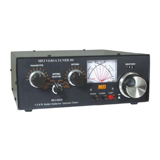
Model MFJ-962D
Requires 9VDC Battery or 12VDC Source for Meter Operation
INSTRUCTION MANUAL
CAUTION: Read All Instructions Before Operating Equipment
MFJ ENTERPRISES, INC.
300 Industrial Park Road
Starkville, MS 39759 USA
Tel: 662-323-5869 Fax: 662-323-6551
COPYRIGHT
C
2013 MFJ ENTERPRISES, INC.
VERSION 5B
Advertisement
Table of Contents

Related Manuals for MFJ VersaTuner III MFJ-962D


Summary of Contents for MFJ VersaTuner III MFJ-962D
- Page 1 Requires 9VDC Battery or 12VDC Source for Meter Operation INSTRUCTION MANUAL CAUTION: Read All Instructions Before Operating Equipment MFJ ENTERPRISES, INC. 300 Industrial Park Road Starkville, MS 39759 USA Tel: 662-323-5869 Fax: 662-323-6551 COPYRIGHT 2013 MFJ ENTERPRISES, INC. VERSION 5B...
- Page 2 Customers using this manual should report errors or omissions, recommendations for improvements, or other comments to MFJ Enterprises, 300 Industrial Park Road, Starkville, MS 39759. Phone: (662) 323- 5869; FAX: (662) 323-6551. Business hours: M-F 8-4:30 CST.
- Page 3 MFJ-962D Instruction Manual Introduction The MFJ-962D is a "T" network roller inductor tuner with built-in antenna switching, RF power and SWR metering and a 1:1 balun. The largest amplifiers that can safely be used include the Heathkit SB- 200 and 201, Collins 30L1, and Ameritron's AL-600 and AL-811 series of amplifiers. This tuner is designed for maximum RF output power levels of 800 watts carrier or PEP on 80-10 meters, and 500 watts carrier or PEP on 160 meters.
- Page 4 2.) 12-VDC External Power: The Meter Lamp power jack is located above the Transmitter connector on the rear panel. Apply power from any filtered dc wall adapter (MFJ-1312D or equivalent), or use your station's 13.8-Vdc supply. A cord fitted with a 2.1-mm plug is supplied with the tuner for this purpose.
- Page 5 The wattmeter has an internal lamp that backlights the meter scale. The lamp circuit requires power from an external 12 Vdc source, such as the optional MFJ-1312B power supply. The rear panel jack accepts a 2.1 mm coaxial plug with the center conductor positive (+) and the sleeve negative (-). The negative lead is grounded inside the tuner.
- Page 6 MFJ-962D Instruction Manual Installation CAUTION: Locate the tuner so that the rear panel is not accessible during operation. 1. Locate the tuner in a convenient location at the operating position. If balanced line operation is used, the ceramic feed through insulators may have high RF voltages. These voltages can cause serious RF burns if the terminals are touched when transmitting.
- Page 7 Adjust the tuner as described below to obtain the best SWR. Do NOT change the transmitter's tuning (plate) or loading (antenna) controls until AFTER the tuner has been fully adjusted. The transmitter can be "touched up" (if necessary) after the MFJ-962D is fully tuned.
- Page 8 MFJ-962D Instruction Manual Note: The MFJ Air Core™ Roller Inductor is designed with an exclusive Self-Resonance Killer™ that keeps potentially damaging self-resonances away from your operating frequency. This feature is switched in and out of the circuit with a built-in switch in the roller. Therefore, as you turn the roller up and down, you may feel a bump.
- Page 9 MFJ-962D Instruction Manual Operating Notes 1. While this tuner is designed to have as large a tuning range as possible, there are limits to the tuning range of the capacitors. Some antennas may require more or less capacitance than the controls have.
- Page 10 For operator safety, a good outside earth ground or water pipe ground should always be installed and connected to the case of the MFJ-962D. Make certain the safety ground also connects to the transmitter and other station accessories. A wing nut post marked GROUND is provided for ground connection(s).
- Page 11 MFJ-962D Instruction Manual Most matching problems occur when the antenna system presents an extremely high impedance to the tuner. When the antenna impedance is much lower than the feedline impedance, an odd quarter- wavelength feedline converts the low antenna impedance to a very high impedance at the tuner. A similar problem occurs if the antenna has an extremely high impedance and the transmission line is a multiple of a half-wavelength.
- Page 12 MFJ-962D Instruction Manual SWR Meter Calibration The MFJ-962D has been calibrated at the factory. If it should ever need to be recalibrated, then follow this procedure: Equipment Needed 1. Transmitter capable of supplying enough power to obtain ½ to full-scale reading at 14 or 21 MHz.
- Page 13 You can also send questions by mail to MFJ Enterprises, INC., 300 Industrial Park Road, Starkville, MS 39759; by Facsimile (FAX) to 662-323-6551; or by email to techinfo@mfjenterprises.com. Send a complete description of your problem, an explanation of exactly how you are using your unit, and a complete description of your station.
- Page 14 MFJ-962D Instruction Manual Logged Tuning Chart Use the chart below to log values for your station. You may want to copy this chart and post it by your tuner. Frequency (MHz) Transmitter Inductor (counter indicator) Antenna 3.75 3.75 3.75 7.15 7.15...
- Page 15 MFJ Enterprises, Inc. warrants to the original owner of this product, if manufactured by MFJ Enterprises, Inc. and purchased from an authorized dealer or directly from MFJ Enterprises, Inc. to be free from defects in material and workmanship for a period of 12 months from date of purchase provided the following terms of this warranty are satisfied.
- Page 16 MFJ-962D Manual 300 Industrial Park Road Version 6 Starkville, MS 39759 Printed In U.S.A.
Need help?
Do you have a question about the VersaTuner III MFJ-962D and is the answer not in the manual?
Questions and answers