Advertisement
MFJ-931 Instruction Manual
IMPORTANT: Please read entire manual before attempting to operate this
equipment. This unit does not provide a DC electric ground. A
separate wire will need to be run from the transmitter to an
electric ground if it is not already available.
Thank you for purchasing the MFJ-931 ARTIFICIAL GROUND. The MFJ-931 creates an
artificial ground with a random length of wire thrown on the floor. This produces a tuned
counterpoise. Also, the MFJ-931 will electrically place a far away RF ground directly at our rig.
Creating Artificial Ground
Connect your transmitter of antenna tuner to the binding post labeled "To Transmitter or
Antenna Tuner Chassis Ground" on the back of the MFJ-931.
Note: This wire needs to be as short as possible, preferably with the ground posts as close as
possible i.e., the units side by side or one on top of the other.
Attach the length of random wire to the red binding post labeled "To Counterpoise Wire or
Ground Connection Wire" on back of the MFJ-931. Be sure not to reverse these wires. The
random wire should be a quarter-wave length or less at the operating frequency. Be sure to
throw the random wire along the floor and to tape up the open end of the wire to avoid RF
burn.
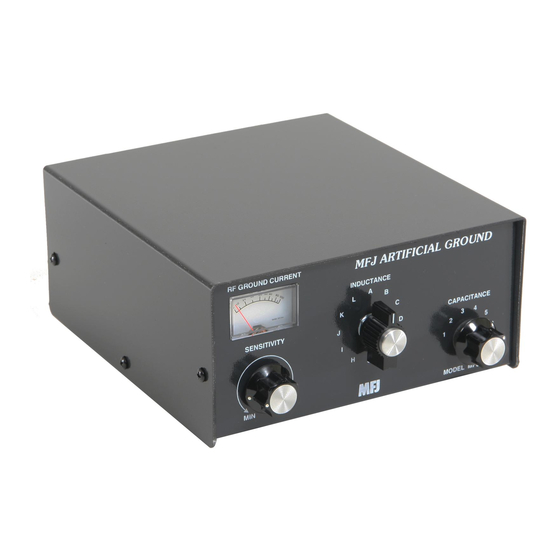
To obtain maximum RF ground current for a low impedance RF ground, alternately adjust the
two controls on the front panel labeled "INDUCTANCE" and "CAPACITANCE". Turn the
INDUCTANCE control first until the highest amount of current can be registered on the built-in
AMMETER. Then adjust the CAPACITANCE control to increase the amount of RF current.
Try several inductance setting for best results. What if the needle goes off the scale or doesn't
move at all? Then the sensitivity of the Ammeter needs to be adjusted. Turn the SENSITIVITY
control until the needle is in the middle of the scale. Then readjust the INDUCTANCE control
for the highest amount of RF current and use the CAPACITANCE control to achieve
maximum RF current. If the needle is still off scale or zero, readjust the SENSITIVITY control
and repeat the tuning process
MFJ ARTIFICIAL GROUND
INSTALLATION AND OPERATION
Artificial RF Ground
Downloaded From TheHamShop.com
Advertisement
Table of Contents

Subscribe to Our Youtube Channel
Related Manuals for MFJ MFJ-931


Summary of Contents for MFJ MFJ-931
- Page 1 Thank you for purchasing the MFJ-931 ARTIFICIAL GROUND. The MFJ-931 creates an artificial ground with a random length of wire thrown on the floor. This produces a tuned counterpoise. Also, the MFJ-931 will electrically place a far away RF ground directly at our rig. INSTALLATION AND OPERATION Creating Artificial Ground Connect your transmitter of antenna tuner to the binding post labeled "To Transmitter or...
- Page 2 Antenna Tuner Chassis Ground" on the back of the MFJ-931 with the shortest possible wire(s). If necessary, place the MFJ-931 and your transmitter or antenna tuner side by side or one on top of the other to insure the ground of each are as close to each other as possible.
- Page 3 In the case of a halfwave antenna, the meter is not usable for measuring ground current, so it is very difficult to tune the artificial ground. You may use a field strength meter, such as the MFJ- 812B, to tune the ground for maximum radiated signal. This also means that the receiving station S-units will go to maximum for this antenna system.
- Page 4 Grounding of the receiving device case can help. If the case is non-metallic, then RF energy is free to invade the internal circuitry. Any wires attached to the device may act as antennas. Installing an RF suppression kit, such as the MFJ-701, can greatly reduce the interference traveling up these lines.
- Page 5 RFI. Harmonics and loss of signal strength can be the result. Energy outside the band may become great enough to radiate into the commercial radio and TV bands. Installing a low pass filter, such as the MFJ-704, will provide additional suppression of the out- of-band signal.
Need help?
Do you have a question about the MFJ-931 and is the answer not in the manual?
Questions and answers