Table of Contents
Advertisement
SVM167-A
RETURN TO MAIN MENU
January, 2011
®
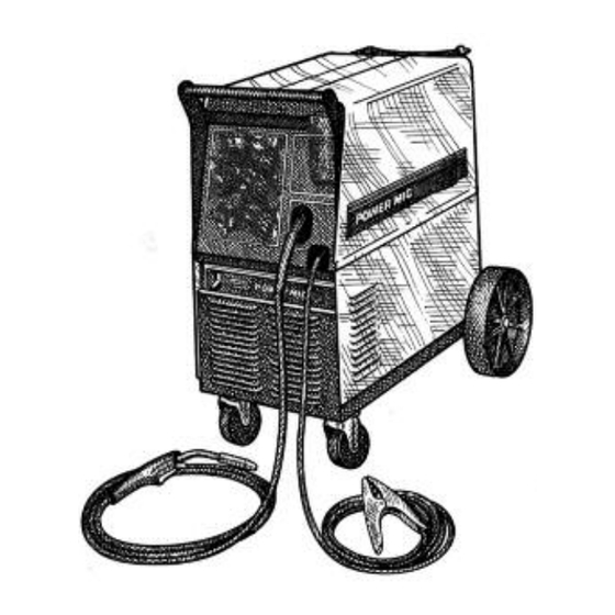
POWER MIG
215
For use with machines having Code Numbers:
11070, 11099, 11247
Safety Depends on You
Lincoln arc welding and cutting
equipment is designed and built
with safety in mind. However,
your overall safety can be
increased by proper installation
... and thoughtful operation on
your part. DO NOT INSTALL,
OPERATE OR REPAIR THIS
EQUIPMENT WITHOUT READ-
ING THIS MANUAL AND THE
SAFETY PRECAUTIONS CON-
TAINED THROUGHOUT. And,
most importantly, think before you
act and be careful.
SERVICE MANUAL
Copyright © Lincoln Global Inc.
• World's Leader in Welding and Cutting Products •
• Sales and Service through Subsidiaries and Distributors Worldwide •
Cleveland, Ohio 44117-1199 U.S.A. TEL: 216.481.8100 FAX: 216.486.1751 WEB SITE: www.lincolnelectric.com
Advertisement
Chapters
Table of Contents
Troubleshooting

Related Manuals for Lincoln Electric POWER MIG SVM167-A


Summary of Contents for Lincoln Electric POWER MIG SVM167-A
-
Page 1: Power Mig
SVM167-A RETURN TO MAIN MENU January, 2011 ® POWER MIG For use with machines having Code Numbers: 11070, 11099, 11247 Safety Depends on You Lincoln arc welding and cutting equipment is designed and built with safety in mind. However, your overall safety can be increased by proper installation ... -
Page 2: California Proposition 65 Warnings
Miami, Florida 33135 or CSA Standard W117.2-1974. A Free copy of “Arc Welding Safety” booklet E205 is available from the Lincoln Electric Company, 22801 St. Clair Avenue, Cleveland, Ohio 44117-1199. BE SURE THAT ALL INSTALLATION, OPERATION, MAINTENANCE AND REPAIR PROCEDURES ARE PERFORMED ONLY BY QUALIFIED INDIVIDUALS. -
Page 3: Electric Shock Can Kill
ELECTRIC SHOCK can kill. 3.a. The electrode and work (or ground) circuits are electrically “hot” when the welder is on. Do not touch these “hot” parts with your bare skin or wet clothing. Wear dry, hole-free gloves to insulate hands. - Page 4 WELDING and CUTTING SPARKS can cause fire or explosion. 6.a. Remove fire hazards from the welding area.If this is not possible, cover them to prevent the welding sparks from starting a fire. Remember that welding sparks and hot materials from welding can easily go through small cracks and openings to adjacent areas.
- Page 5 PRÉCAUTIONS DE SÛRETÉ Pour votre propre protection lire et observer toutes les instructions et les précautions de sûreté specifiques qui parraissent dans ce manuel aussi bien que les précautions de sûreté générales suiv- antes: Sûreté Pour Soudage A L’Arc 1. Protegez-vous contre la secousse électrique: a.
-
Page 6: Table Of Contents
RETURN TO MAIN MENU MASTER TABLE OF CONTENTS FOR ALL SECTIONS Page Safety ............i-iv Installation . - Page 7 Section A - INSTALLATION SECTION - Installation ........... Section A Technical Specifications .
-
Page 8: Installation
TECHNICAL SPECIFICATIONS – POWER MIG® 215 Standard Voltage/Phase/Frequency 208/230/1/50/60 Hz Duty Cycle Welding Current Range 30 – 250Amps RECOMMENDED INPUT WIRE AND FUSE SIZES Input Voltage/ Fuse or Breaker Frequency (Hz) Size (Super Lag) 208/50/60 230/50/60 Wire Speed Height 31.79 in 808 mm OPERATING TEMPERATURE RANGE -4°F to 104°F(-20°C to +40°C) -
Page 9: Installation
Roll the machine off the skid assembly. LOCATION Locate the welder in a dry location where there is free circulation of clean air into the louvers in the back and out the front. A location that minimizes the amount of... -
Page 10: Output Polarity Connections
A green wire in the input cable connects this contact to the frame of the welder. This ensures proper grounding of the welder frame when the welder plug is inserted into a grounded receptacle. FIGURE A.2 — Receptacle Diagram CONNECT TO A SYSTEM GROUNDING WIRE. -
Page 11: Gun And Cable Installation
Be sure that the contact tip, liner, and drive rolls all match the size of the wire being used. WARNING Turn the welder power switch off before installing gun and cable. 1. Lay the cable out straight. - Page 12 NOTES POWER MIG® 215...
- Page 13 Wire Drive Roll...B-3 Wire Size Conversion parts...B-3 Procedure for Changing Drive Roll...B-4 Wire Reel Loading ...B-4 Mounting of 10 to 44 lbs. Spools...B-4 To Start the Welder...B-4 Feeding Electrode ...B-5 Idle Roll Pressure Setting...B-5 Wire Drive Configuration ...B-5 Making a Weld...B-6 Avoiding Wire Feeding Problems ...B-7...
-
Page 14: Power
Read entire Operation section before operating the POWER MIG® 215. Observe all safety information throughout this manual. OPERATION WARNING ELECTRIC SHOCK can kill. • Do not touch electrically live parts or electrode with skin or wet cloth- ing. Insulate yourself from work and ground. -
Page 15: Product Description
PRODUCT DESCRIPTION The POWER MIG® 215 is a complete semiautomatic DC voltage arc welding machine built to meet NEMA specifications. It combines a tapped transformer volt- age power source with a constant speed wire feeder to form a reliable robust performance welding system. A simple control scheme, consisting of continuous full range wire feed speed control, and 7 output voltage tap selections provides versatility with ease of use and... -
Page 16: Procedure For Changing Drive And Idle Roll Sets
TO START THE WELDER Turn the “Power Switch” switch to “ON”. With the desired voltage and wire speed selected, operate the gun trigger for welder output and to energize the wire feed motor. POWER MIG®... -
Page 17: Feeding Electrode
FEEDING WIRE ELECTRODE WARNING When triggering, the electrode and drive mechanism are electrically “hot” relative to work and ground and remain “hot” several seconds after the gun trigger is released. ------------------------------------------------------------------------ NOTE: Check that drive rolls, guide plates and gun parts are proper for the wire size and type being used. -
Page 18: Making A Weld
5. Loosen the socket head cap screw that holds the connector bar against the gun bushing. Important: Do attempt remove the socket head cap screw. 6. Remove the outer wire guide, and push the gun bushing out of the wire drive. Because of the pre- cision fit, light tapping may be required to remove the gun bushing. -
Page 19: Avoiding Wire Feeding Problems
The POWER MIG® 215 has built-in protective ther- mostats that respond to excessive temperature. They open the wire feed and welder output circuits if the machine exceeds the maximum safe operating tem- perature because of a frequent overload, or high ambi- ent temperature plus overload. - Page 20 NOTES POWER MIG® 215...
-
Page 21: Accessories Section
Section C - ACCESSORIES SECTION - Accessories ..........Section C Drive Roll Kits . -
Page 22: Alternative Magnum Gmaw Gun And Cable Assemblies
DRIVE ROLL KITS Refer to Table C.1 for various drive roll kits that are available for the POWER MIG® 215.The item in Bold is supplied standard with the POWER MIG® 215. Wire Size .023”-.030” (0.6-0.8 mm) Solid .035” (0.9 mm) Steel .045”... -
Page 23: Making A Weld With The Spool Gun Adapter Kit And Spool Gun Installed
MAKING A WELD WITH THE SPOOL GUN ADAPTER KIT AND SPOOL GUN INSTALLED CAUTION In either toggle switch position, closing either gun trigger will cause the electrode of both guns to be electrically “HOT”. Be sure unused gun is posi- tioned so electrode or tip will not contact metal case or other metal common to work. - Page 24 NOTES POWER MIG® 215...
-
Page 25: Maintenance Section
Section D - MAINTENANCE SECTION - Maintenance ..........Section D Safety Precautions . -
Page 26: General Maintenance
GENERAL MAINTENANCE In extremely dusty locations, dirt may clog the air pas- sages causing the welder to run hot. Blow dirt out of the welder with low-pressure air at regular intervals to eliminate excessive dirt and dust build-up on internal parts. -
Page 27: Maintenance
LINER REMOVAL AND REPLACE- MENT NOTE: Changing the liner for a different wire size requires replacement of the gas diffuser per Table D.1 to properly secure the different liner. Diameter of Electrodes Used .025-.030" Steel (0.6-0.8 mm) .035-.045" Steel (0.9-1.2 mm) 3/64"... -
Page 28: Gun Handle Disassembly
GUN HANDLE DISASSEMBLY The internal parts of the gun handle may be inspected or serviced if necessary. The gun handle consists of two halves that are held together with a collar on each end. To open up the handle, turn the collars approximately 60 degrees counterclockwise (the same direction as removing a right hand thread) until the collar reaches a stop. - Page 29 MAINTENANCE FIGURE D.2 – MAJOR COMPONENT LOCATIONS 1. Case Front Assembly 2. Rear Panel Assembly 3. Center Assembly 4. Wire Drive Assembly 5. Base & Power Component Assembly 6. Covers Assembly POWER MIG® 215...
- Page 30 NOTES POWER MIG® 215...
-
Page 31: Theory Of Operation Section
Section E - THEORY OF OPERATION SECTION - Theory of Operation ......... . . Section E Input Power Circuit . -
Page 32: Theory Of Operation
THEORY OF OPERATION FIGURE E.2 – INPUT POWER CIRCUIT. RECTIFIER MOTOR DIODE BRIDGE LINE SWITCH RECONNECT MAIN PANEL TRANSFORMER INPUT LINE VOLTAGE, MAIN TRANSFORMER, VOLTAGE SELECTOR SWITCH AND BAFFLE MOUNTED DIODE BRIDGE The single phase input power is connected to the POWER MIG®... - Page 33 THEORY OF OPERATION RECTIFIER MOTOR DIODE BRIDGE LINE SWITCH RECONNECT MAIN PANEL TRANSFORMER OUTPUT RECTIFICATION, CONTACTOR AND CONTROL BOARD The AC voltage developed on the secondary winding is applied, through the selector switch and output contactor, to the output rectifier bridge.
- Page 34 THEORY OF OPERATION FIGURE E.4 – OPTIONAL CIRCUITS. RECTIFIER MOTOR DIODE BRIDGE LINE SWITCH RECONNECT MAIN PANEL TRANSFORMER CONTROL BOARD, GUN TRIGGER AND WIRE DRIVE MOTOR When the control board receives an activation command from the trigger circuit the control board supplies 12VDC which activates the gas solenoid and output contactor.
-
Page 35: Protective Devices And Circuits
One is located on the main transformer. thermostat is located on the output rectifier heat sink assembly. They open the wire feed and welder output circuits if the machine exceeds the maximum safe operating temperature. This can be caused by a frequent overload or high ambient temperature. - Page 36 NOTES POWER MIG® 215...
- Page 37 Section F - TROUBLESHOOTING AND REPAIR SECTION - Troubleshooting and Repair ........Section F How to Use Troubleshooting Guide .
-
Page 38: Troubleshooting And Repair
TROUBLESHOOTING AND REPAIR How To Use Troubleshooting Guide Service and Repair should only be performed by Lincoln Electric Factory Trained Personnel. Unauthorized repairs performed on this equipment may result in danger to the technician and machine operator and will invalidate your factory warranty. For your safety and to avoid Electrical Shock, please observe all safety notes and precautions detailed throughout this manual. -
Page 39: Pc Board Troubleshooting Procedures
TROUBLESHOOTING AND REPAIR PC BOARD TROUBLESHOOTING PROCEDURES WARNING ELECTRIC SHOCK can kill. • Have install and service this equipment. Turn the input power fuse box before working on equipment. Do not touch electrically hot parts. CAUTION Sometimes machine failures appear to be due to PC board failures. -
Page 40: Troubleshooting And Repair
If for any reason you do not understand the test procedures or are unable to perform the tests/repairs safely, contact the Lincoln Electric Service Department for technical troubleshooting assistance before you proceed. Call 1-888-935-3877. See Wiring Diagrams for location of specified... - Page 41 If for any reason you do not understand the test procedures or are unable to perform the tests/repairs safely, contact the Lincoln Electric Service Department for technical troubleshooting assistance before you proceed. Call 1-888-935-3877.
- Page 42 The wire feed functions normal- If for any reason you do not understand the test procedures or are unable to perform the tests/repairs safely, contact the Lincoln Electric Service Department for technical troubleshooting assistance before you proceed. Call 1-888-935-3877.
- Page 43 If for any reason you do not understand the test procedures or are unable to perform the tests/repairs safely, contact the Lincoln Electric Service Department for technical troubleshooting assistance before you proceed. Call 1-888-935-3877 See Wiring Diagrams for location of specified...
- Page 44 If for any reason you do not understand the test procedures or are unable to perform the tests/repairs safely, contact the Lincoln Electric Service Department for technical troubleshooting assistance before you proceed. Call 1-888-935-3877 See Wiring Diagrams for location of specified...
- Page 45 If for any reason you do not understand the test procedures or are unable to perform the tests/repairs safely, contact the Lincoln Electric Service Department for technical troubleshooting assistance before you proceed. Call 1-888-935-3877 See Wiring Diagrams for location of specified...
- Page 46 If for any reason you do not understand the test procedures or are unable to perform the tests/repairs safely, contact the Lincoln Electric Service Department for technical troubleshooting assistance before you proceed. Call 1-888-935-3877 See Wiring Diagrams for location of specified...
-
Page 47: Main Transformer Test
TROUBLESHOOTING AND REPAIR MAIN TRANSFORMER TEST WARNING Service and repair should only be performed by Lincoln Electric factory trained personnel. Unauthorized repairs performed on this equipment may result in danger to the technician or machine operator and will invalidate your factory warranty. -
Page 48: Test Procedure
F-12 TROUBLESHOOTING AND REPAIR MAIN TRANSFORMER TEST (continued) FIGURE F.1. – OUTPUT SELECTOR SWITCH TERMINALS TEST PROCEDURE WARNING THE ON/OFF POWER SWITCH will be “hot” during these tests. NOTE: Secondary voltages will vary proportionately with the primary input voltage. 1. Disconnect the main input power supply to the machine. - Page 49 F-13 F-13 TROUBLESHOOTING AND REPAIR MAIN TRANSFORMER TEST (continued) FIGURE F.2. – LEAD X1 FIGURE F.3. – LEAD X9 & X10 POWER MIG® 215...
- Page 50 F-14 TROUBLESHOOTING AND REPAIR INPUT VOLTAGE 230 VAC 230 VAC 230 VAC 230 VAC 230 VAC 230 VAC 230 VAC 230 VAC 12. If ALL the voltages tested are incorrect or missing, test for correct nameplate input voltage between the H1 lead at the ON/OFF POWER SWITCH to H2 or H3 at the reconnect panel.
-
Page 51: Wire Drive Motor And Wire Speed Potentiometer Test
WIRE DRIVE MOTOR AND WIRE SPEED POTENTIOMETER TEST WARNING Service and repair should only be performed by Lincoln Electric factory trained personnel. Unauthorized repairs performed on this equipment may result in danger to the technician or machine operator and will invalidate your factory warranty. - Page 52 F-16 TROUBLESHOOTING AND REPAIR WIRE DRIVE MOTOR AND WIRE SPEED POTENTIOMETER TEST 1. Make the following voltage tests: WARNING ELECTRIC SHOCK can kill. • Do not touch electrically live parts such as output terminals or internal wiring. • All input power must be electri- cally disconnected before pro- ceeding.
- Page 53 F-17 TROUBLESHOOTING AND REPAIR WIRE DRIVE MOTOR AND WIRE SPEED POTENTIOMETER TEST TEST FOR FEEDBACK VOLTAGE TO CONTROL BOARD 1. Disconnect the main AC input power to the machine. 2. Locate plug J1 and the potentiometer leads. See Figure F.5. #1113A and 1109A.
- Page 54 F-18 F-18 NOTES POWER MIG® 215...
-
Page 55: Output Bridge Rectifier Test
TROUBLESHOOTING AND REPAIR OUTPUT BRIDGE RECTIFIER TEST Service and repair should only be performed by Lincoln Electric factory trained personnel. Unauthorized repairs performed on this equipment may result in danger to the technician or machine operator and will invalidate your factory warranty. - Page 56 F-20 TROUBLESHOOTING AND REPAIR OUTPUT BRIDGE RECTIFIER TEST (continued) TEST PROCEDURE 1. Remove input power to the POWER MIG® 215 machine. 2. Using the 3/8” nutdriver, remove the left case side. 3. Locate and disconnect the negative lead from the output rectifier bridge assembly. Be sure there is no electrical contact between the rectifier and the lead.
-
Page 57: Contactor Test
F-21 TROUBLESHOOTING AND REPAIR Service and repair should only be performed by Lincoln Electric factory trained personnel. Unauthorized repairs performed on this equipment may result in danger to the technician or machine operator and will invalidate your factory warranty. For your safety and to avoid electrical shock please observe all safety notes and precautions detailed throughout this manual. - Page 58 F-22 TROUBLESHOOTING AND REPAIR CONTACTOR TEST (Continued) TEST PROCEDURE 1. Remove the input power to the POWER MIG® 215 machine. 2. Using the 5/16” Nutdriver, remove the tool tray. 3. Locate and remove leads 106B, 106C and 107A from the contactor coil terminals.
-
Page 59: Typical Output Voltage Waveform - Machine Loaded
F-23 TROUBLESHOOTING AND REPAIR TYPICAL OUTPUT VOLTAGE WAVEFORM - MACHINE LOADED 10.0 V MACHINE LOADED TO 200 AMPS AT 22 VDC This is a typical DC output voltage wave- form generated from a properly operat- ing machine. Note that each vertical division represents 10 volts and that each horizontal division represents 5 milliseconds in time. - Page 60 F-24 TROUBLESHOOTING AND REPAIR NORMAL OPEN CIRCUIT VOLTAGE WAVEFORM (MAX TAP “G”) 20.0 V This is a typical DC output voltage wave- form generated from a properly operat- ing machine. Note that each vertical division represents 20 volts and that each horizontal division represents 1.0 milliseconds in time.
- Page 61 F-25 TROUBLESHOOTING AND REPAIR ABNORMAL OUTPUT VOLTAGE WAVEFORM - MACHINE ONE OUTPUT DIODE NOT FUNCTIONING 20.0 V MACHINE LOADED TO 180 AMPS AT 16 VDC This is NOT a typical DC output voltage waveform. One output diode is not func- tioning.
- Page 62 F-26 TROUBLESHOOTING AND REPAIR ABNORMAL OPEN CIRCUIT VOLTAGE OUTPUT CAPACITOR BANK NOT FUNCTIONING (MAX TAP “G”) 20.0 V This is NOT a typical DC output voltage waveform. The output capacitors are not functioning. Note the lack of “filter- ing” in the output waveform. The output capacitor bank was disconnected.
-
Page 63: Control Board Replacement
TROUBLESHOOTING AND REPAIR CONTROL BOARD REPLACEMENT Service and repair should only be performed by Lincoln Electric factory trained personnel. Unauthorized repairs performed on this equipment may result in danger to the technician or machine operator and will invalidate your factory warranty. - Page 64 F-28 TROUBLESHOOTING AND REPAIR CONTROL BOARD REPLACEMENT (continued) PROCEDURE 1. Remove power to the machine. 2. Using a 5/16” nutdriver, remove the three screws securing the tool tray. 3. Locate the control board. 4. Disconnect all associated plugs and leads connected to the control board.
-
Page 65: Wire Drive Motor Assembly Replacement
TROUBLESHOOTING AND REPAIR WIRE DRIVE MOTOR ASSEMBLY REPLACEMENT Service and repair should only be performed by Lincoln Electric factory trained personnel. Unauthorized repairs performed on this equipment may result in danger to the technician or machine operator and will invalidate your factory warranty. - Page 66 F-30 TROUBLESHOOTING AND REPAIR WIRE DRIVE MOTOR ASSEMBLY REPLACEMENT (Continued) FIGURE F.9. - WIRE DRIVE LOCATION PROCEDURE 1. Remove power to the machine. 2. Lift cover to gain access to the wire drive. See Figure F.9. 3. Using a pair of pliers, disconnect the gas hose from the bottom of the wire drive.
- Page 67 F-31 TROUBLESHOOTING AND REPAIR WIRE DRIVE MOTOR ASSEMBLY REPLACEMENT (Continued) FIGURE F.10. - WIRE DRIVE HOSE & LEAD LOCATION 5/16" Monuting Screws FIGURE F.11. - MOUNTING SCREW LOCATIONS 5/16" Sheet Metal Screws 9/16" Bolt Gas Hose POWER MIG® 215 F-31...
- Page 68 F-32 TROUBLESHOOTING AND REPAIR WIRE DRIVE MOTOR ASSEMBLY REPLACEMENT (Continued) 1. Place the new wire drive assembly into its proper position. 2. Connect plug J4. 3. Maneuver assembly back into its original position. 4. Replace all mounting screws previously removed. 5.
-
Page 69: Output Diode Bridge Rectifier Replacement
TROUBLESHOOTING AND REPAIR OUTPUT DIODE BRIDGE RECTIFIER REPLACEMENT Service and repair should only be performed by Lincoln Electric factory trained personnel. Unauthorized repairs performed on this equipment may result in danger to the technician or machine operator and will invalidate your factory warranty. - Page 70 F-34 TROUBLESHOOTING AND REPAIR OUTPUT DIODE BRIDGE RECTIFIER REPLACEMENT (CONTINUED) PROCEDURE 1. Using a 3/8” nutdriver, remove the left side of the case wraparound cover. 2. Locate the output diode bridge rectifier. See Figure F.12. 3. Using a 1/2” nutdriver label and remove the four thick black leads connected to the rectifier.
- Page 71 F-35 TROUBLESHOOTING AND REPAIR OUTPUT DIODE BRIDGE RECTIFIER REPLACEMENT (CONTINUED) FIGURE F.13. - OUTPUT DIODE BRIDGE RECTIFIER MOUNTING BRACKET 1/2" Rectifier Mounting Bolts 5/16" Mounting Bracket Mounting Bolts POWER MIG® 215 F-35 Mounting Bracket...
- Page 72 F-36 F-36 NOTES POWER MIG® 215...
-
Page 73: Output Capacitors Replacement
TROUBLESHOOTING AND REPAIR OUTPUT CAPACITORS REPLACEMENT Service and repair should only be performed by Lincoln Electric factory trained personnel. Unauthorized repairs performed on this equipment may result in danger to the technician or machine operator and will invalidate your factory warranty. - Page 74 F-38 TROUBLESHOOTING AND REPAIR OUTPUT CAPACITORS REPLACEMENT (Continued) PROCEDURE 1. Using a 3/8” nutdriver, remove the lower right side case wraparound cover. See Figure F.14. 2. Locate capacitor bank. See Figure F.14. 3. Label and remove the five leads connected to the capacitor bank using a 1/2”...
- Page 75 F-39 F-39 TROUBLESHOOTING AND REPAIR OUTPUT CAPACITORS REPLACEMENT (Continued) FIGURE F.15. - MOUNTING SCREW/BOLT LOCATIONS Lead Mounting Bolts 3/8" Nuts & Lock washers (3 places) POWER MIG® 215...
- Page 76 F-40 F-40 NOTES POWER MIG® 215...
-
Page 77: Main Transformer Replacement
TROUBLESHOOTING AND REPAIR MAIN TRANSFORMER REPLACEMENT Service and repair should only be performed by Lincoln Electric factory trained personnel. Unauthorized repairs performed on this equipment may result in danger to the technician or machine operator and will invalidate your factory warranty. -
Page 78: Main Transformer
F-42 TROUBLESHOOTING AND REPAIR MAIN TRANSFORMER REPLACEMENT (Continued) PROCEDURE 1. Using a 3/8” nutdriver, remove both sides of the case wraparound cover. 2. Using a 5/16” nutdriver, remove the tool tray. 3. Locate the main transformer. See Figure F.16. 4. Label and disconnect leads X9, X10, 104B, &... - Page 79 F-43 TROUBLESHOOTING AND REPAIR MAIN TRANSFORMER REPLACEMENT (Continued) 15. Carefully maneuver the main transformer out the left side of the machine. NOTE: Two people may be needed to maneu- ver the main transformer out of the machine. REPLACEMENT 1. Carefully maneuver the new main trans- former back into the machine and onto its mounting studs.
- Page 80 F-44 F-44 TROUBLESHOOTING AND REPAIR MAIN TRANSFORMER REPLACEMENT (Continued) FIGURE F.18. - LEADS SWITCH LEADS FIGURE F.19. - LEAD 121 & 118 POWER MIG® 215...
- Page 81 F-45 F-45 TROUBLESHOOTING AND REPAIR MAIN TRANSFORMER REPLACEMENT (Continued) FIGURE F.20. - REAR ACCESS PANEL 5/16" Nut REAR ACCESS PANEL Lead 118 230V 208V FIGURE F.21. - REAR ACCESS PANEL (CLOSE-UP) POWER MIG® 215...
- Page 82 F-46 F-46 NOTES POWER MIG® 215...
-
Page 83: Fan Blade/Motor Replacement
TROUBLESHOOTING AND REPAIR FAN BLADE/MOTOR REPLACEMENT Service and repair should only be performed by Lincoln Electric factory trained personnel. Unauthorized repairs performed on this equipment may result in danger to the technician or machine operator and will invalidate your factory warranty. - Page 84 F-48 TROUBLESHOOTING AND REPAIR FAN BLADE/MOTOR REPLACEMENT (Continued) PROCEDURE 1. Using a 3/8” nutdriver, remove the lower right side of the case wraparound cover. 2. Perform the Output Capacitor Bank Removal Procedure. 3. Using a 5/16” nutdriver, remove the four fan mounting screws from the rear of the machine.
-
Page 85: Output Contactor Replacement
TROUBLESHOOTING AND REPAIR OUTPUT CONTACTOR REPLACEMENT Service and repair should only be performed by Lincoln Electric factory trained personnel. Unauthorized repairs performed on this equipment may result in danger to the technician or machine operator and will invalidate your factory warranty. - Page 86 F-50 TROUBLESHOOTING AND REPAIR OUTPUT CONTACTOR REPLACEMENT (Continued) PROCEDURE 1. Using a 5/16” nutdriver, remove the three screws securing the tool tray. 2. Locate the output contactor. F.23. 3. Using a 7/16” wrench, label and remove the two thick black leads at the top of the output contactor.
- Page 87 F-51 F-51 TROUBLESHOOTING AND REPAIR OUTPUT CONTACTOR REPLACEMENT (Continued) FIGURE F.24. - OUTPUT CONTACTOR MOUNTING BOLTS 7/16" Mounting Bolts POWER MIG® 215...
-
Page 88: Retest After Repair
F-52 F-52 TROUBLESHOOTING AND REPAIR RETEST AFTER REPAIR INPUT IDLE AMPS AND WATTS Input Volts/Herts Maximum Idle Amps Maximum Idle Watts 230/60 OPEN CIRCUIT VOLTAGE 35 - 40 VDC WIRE SPEED RANGE 50 - 700 IPM (1.27 - 17.8 m/minute) POWER MIG®... -
Page 89: Electrical Diagrams Section
-ELECTRICAL DIAGRAMS SECTION- ELECTRICAL DIAGRAMS ............SECTION G WIRING DIAGRAM - COMPLETE MACHINE - CODE 11070 - (L11986) . -
Page 90: Electrical Diagrams
WiriNG DiaGram - cOmplETE machiNE - cODE 11070 - (l11986) CAVITY NUMBERING SEQUENCE (COMPONENT SIDE OF P.C. BOARD) TO SINGLE PHASE SUPPLY LINE 208V RECONNECT PANEL TO GROUND PER NATIONAL ELECTRICAL CODE NOTE: This diagram is for reference only. It may not be accurate for all machines covered by this manual. The wiring diagram specific to your code is pasted inside one of the enclosure panels of your machine. ElEcTrical DiaGramS POWER MIG 215 (208/220/230V) GENERAL INFORMATION... -
Page 91: Wiring Diagram - Complete Machine - Code 11099, 11247 - (L12184)
WiriNG DiaGram - cOmplETE machiNE - cODE 11099, 11247 - (l12184) CAVITY NUMBERING SEQUENCE (COMPONENT SIDE OF P.C. BOARD) TO SINGLE PHASE SUPPLY LINE 208V RECONNECT PANEL TO GROUND PER NATIONAL ELECTRICAL CODE NOTE: This diagram is for reference only. It may not be accurate for all machines covered by this manual. The wiring diagram specific to your code is pasted inside one of the enclosure panels of your machine. ElEcTrical DiaGramS POWER MIG 215 (208/220/230V) GENERAL INFORMATION... -
Page 92: Schematic - Complete Machine - Code 11247 - (L12308/1
SchEmaTic - cOmplETE machiNE - cODE 11247 - (l12308 pG1) L12308 ENGINEERING CONTROLLED MANUFACTURER: LOCATEDON CASEBACK TO SINGLE PHASE SUPPLY LINE TO GROUND PER NATIONAL ELECTRICAL CODE ElEcTrical DiaGramS CHANGE DETAIL: NEW. 40 VDC 1106A X9 1114A RECTIFIER DIODE BRIDGE MOVED TO CONTROL BOARD ON CODE 11099 AND HIGHER... -
Page 93: Schematic - Complete Machine - Code 11247 - (L12308/2
SchEmaTic - cOmplETE machiNE - cODE 11247 - (l12308 pG2) L12308 ENGINEERING CONTROLLED MANUFACTURER: ElEcTrical DiaGramS CHANGE DETAIL: NEW. GAS SOLENOID GAS SOLENOID + GAS SOLENOID - LOCATEDON LOCATEDON SPOOL GUN CASEBACK CASEBACK ADAPTER PANEL V=8.7VDCW HENGASISFLOW ING LOCATEDON COIL: 21.6OHMS, 12VDCCOIL DIVIDERPANEL INW IREDRIVE MOTOR+SPEEDCONTROL... -
Page 94: Schematic - Common Analog Wiredrive Pc Board - Code 11070 - (G3850 Pg1
ElEcTrical DiaGramS SchEmaTic - cOmmON aNalOG WirEDriVE pc bOarD - cODE 11070 - (G3850 pG1) NOTE: This diagram is for reference only. It may not be accurate for all machines covered by this manual. pOWEr miG® 215... -
Page 95: Schematic - Common Analog Wiredrive Pc Board - Code 11070 - (G3850 Pg2
ElEcTrical DiaGramS SchEmaTic - cOmmON aNalOG WirEDriVE pc bOarD - cODE 11070 - (G3850 pG2) NOTE: This diagram is for reference only. It may not be accurate for all machines covered by this manual. pOWEr miG® 215... -
Page 96: Schematic - Common Analog Wiredrive Pc Board - Code 11070 - (G3850 Pg3
ElEcTrical DiaGramS SchEmaTic - cOmmON aNalOG WirEDriVE pc bOarD - cODE 11070 - (G3850 pG3) NOTE: This diagram is for reference only. It may not be accurate for all machines covered by this manual. pOWEr miG® 215... -
Page 97: Schematic-Common Analog Wiredrive Pc Board-Code 11099, 11247 - (G4414 Pg1
ElEcTrical DiaGramS SchEmaTic - cOmmON aNalOG WirEDriVE pc bOarD - cODE 11099, 11247 - (G4414 pG1) NOTE: This diagram is for reference only. It may not be accurate for all machines covered by this manual. pOWEr miG® 215... -
Page 98: Schematic-Common Analog Wiredrive Pc Board-Code 11099, 11247 - (G4414 Pg2
G-10 G-10 ElEcTrical DiaGramS SchEmaTic - cOmmON aNalOG WirEDriVE pc bOarD - cODE 11099, 11247 - (G4414 pG2) NOTE: This diagram is for reference only. It may not be accurate for all machines covered by this manual. pOWEr miG® 215... -
Page 99: Schematic-Common Analog Wiredrive Pc Board-Code 11099, 11247 - (G4414 Pg3
G-11 G-11 ElEcTrical DiaGramS SchEmaTic - cOmmON aNalOG WirEDriVE pc bOarD - cODE 11099, 11247 - (G4414 pG3) NOTE: This diagram is for reference only. It may not be accurate for all machines covered by this manual. pOWEr miG® 215...
Need help?
Do you have a question about the POWER MIG SVM167-A and is the answer not in the manual?
Questions and answers