Sony TA-SB500WR2 Service Manual
Surround amplifier
Hide thumbs
Also See for TA-SB500WR2:
- Service manual (30 pages) ,
- Specifications (4 pages) ,
- Supplementary manual (1 page)
Table of Contents
Advertisement
QQ
3 7 63 1515 0
SERVICE MANUAL
Ver. 1.0 2007.03
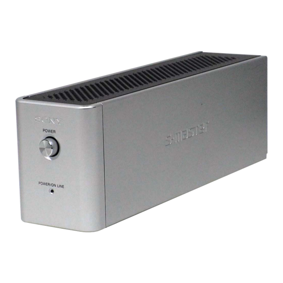
• TA-SB500WR2 is the surround amplifier
section in DAV-HDX267W/HDX501W.
AUDIO POWER SPECIFICATIONS
POWER OUTPUT AND TOTAL HARMONIC
DISTORTION:
TE
L 13942296513
Amplifier section
Surround mode (reference) RMS output power
* Depending on the sound field setting and the source,
there may be no sound output.
www
.
Sony Corporation
9-887-591-01
Home Audio Division
2007C05-1
Published by Sony Techno Create Corporation
© 2007.03
http://www.xiaoyu163.com
TA-SB500WR2
With 3 ohms loads, both
channels driven, from
120 Hz - 20,000 Hz; rated
60 watts per channel
minimum RMS power,
with no more than 0.7 %
total harmonic distortion
from 250 milli watts to
rated output.
SL/SR* : 100 W
(per channel at 3 ohms, 1
kHz, 10 % THD)
x
ao
u163
y
i
http://www.xiaoyu163.com
2 9
8
SPECIFICATIONS
Power requirements:
Power consumption
Dimensions (approx.)
Q Q
3
6 7
1 3
1 5
Mass (approx.)
Design and specifications are subject to change
without notice.
co
.
9 4
2 8
US Model
120 V AC, 60 Hz
On: 40 W
65 × 89 × 253 mm
× 3
× 10 inches)
(2
/
/
5
5
8
8
(w/h/d)
65 × 89 × 345 mm
0 5
8
2 9
9 4
2 8
3 ×
× 13
(2
5
/
5
/
5
/
inches)
8
8
8
(w/h/d) incl. speaker cord
cover
1.3 kg (2 lb 14 oz)
1.4 kg (3 lb 2 oz) incl.
speaker cord cover
m
SURROUND AMPLIFIER
9 9
9 9
Advertisement
Table of Contents

Related Manuals for Sony TA-SB500WR2


Summary of Contents for Sony TA-SB500WR2
-
Page 1: Service Manual
TA-SB500WR2 3 7 63 1515 0 SERVICE MANUAL US Model Ver. 1.0 2007.03 • TA-SB500WR2 is the surround amplifier section in DAV-HDX267W/HDX501W. SPECIFICATIONS AUDIO POWER SPECIFICATIONS Power requirements: 120 V AC, 60 Hz Power consumption On: 40 W POWER OUTPUT AND TOTAL HARMONIC 65 ×... -
Page 2: Table Of Contents
COMPONENTS IDENTIFIED BY MARK 0 OR DOTTED LINE WITH MARK 0 ON THE SCHEMATIC DIAGRAMS AND IN THE PARTS LIST ARE CRITICAL TO SAFE OPERATION. REPLACE THESE COMPONENTS WITH SONY PARTS WHOSE PART NUMBERS APPEAR AS SHOWN IN THIS MANUAL OR IN SUPPLEMENTS PUBLISHED BY SONY. -
Page 3: General
TA-SB500WR2 SECTION 1 This section is extracted from instruction manual. GENERAL 3 7 63 1515 0 LOCATION OF CONTROLS Surround amplifier Front panel Rear panel POWER DIR-R1 SPEAKER SURROUND L POWER ON-LINE SURROUND R A POWER (ON/OFF) B POWER/ON LINE indicator... -
Page 4: Disassembly
TA-SB500WR2 SECTION 2 DISASSEMBLY 3 7 63 1515 0 • This set can be disassembled in the order shown below. 2-1. DISASSEMBLY FLOW 2-2. WIRE COVER (Page 4) 2-3. TOP PANEL (Page 5) 2-4. SIDE PANEL, FRONT PANEL BLOCK (Page 5) 2-5. -
Page 5: Top Panel
TA-SB500WR2 3 7 63 1515 0 2-3. TOP PANEL 1 screw 4 top panel (BVTP3 × 10) 3 eight claws 2-4. SIDE PANEL, FRONT PANEL BLOCK L 13942296513 3 side panel 1 six screws (2.6 × 6) 7 connector... -
Page 6: Diat Power Board
TA-SB500WR2 3 7 63 1515 0 2-5. DIAT POWER BOARD 7 power shield 8 radiation sheet (DMB) 8 radiation sheet 2 two claws 4 two connectors (CN904) 9 fuse (F901) 5 four screws (2.6 × 6) 0 DIAT POWER board... -
Page 7: Diagrams
TA-SB500WR2 SECTION 3 3 7 6 3 1 5 1 5 0 DIAGRAMS 3-1. BLOCK DIAGRAM • SIGNAL PATH : AUDIO VCC2 IC102 IC301 TB301 RF DEMODULATOR, IC110 STREAM PROCESSOR A/D CONVERTER SPEAKER POWER DRIVER J301 10 ADVIN DAOUT... - Page 8 TA-SB500WR2 3 7 6 3 1 5 1 5 0 • Note for Printed Wiring Boards and Schematic Diagrams • Waveforms Note on Printed Wiring Boards: Note on Schematic Diagram: – DIAT AMP Board – • X : parts extracted from the component side.
-
Page 9: Printed Wiring Board - Diat Amp Section (1/2)
TA-SB500WR2 3 7 6 3 1 5 1 5 0 3-2. PRINTED WIRING BOARD – DIAT AMP Section (1/2) – : Uses unleaded solder. DIAT AMP BOARD (COMPONENT SIDE) R940 R950 R941 C951 IC904 D922 C938 C937 R259 R122... -
Page 10: Printed Wiring Boards - Diat Amp Section (2/2)
TA-SB500WR2 3 7 6 3 1 5 1 5 0 3-3. PRINTED WIRING BOARDS – DIAT AMP Section (2/2) – : Uses unleaded solder. (Page 15) DIAT AMP BOARD DIAT POWER (CONDUCTOR SIDE) BOARD CN904 (CHASSIS) R943 R942 C385... -
Page 11: Schematic Diagram - Diat Amp Section (1/4)
TA-SB500WR2 • See page 8 for Waveforms. • See page 17 for IC Block Diagrams. 3-4. SCHEMATIC DIAGRAM – DIAT AMP Section (1/4) – 3 7 6 3 1 5 1 5 0 DIAT AMP BOARD (1/4) C137 IC104 IC B/D +2.5V REGULATOR... -
Page 12: Schematic Diagram - Diat Amp Section (2/4)
TA-SB500WR2 • See page 8 for Waveforms. • See page 17 for IC Block Diagrams. • See page 21 for IC Pin Function Description. 3-5. SCHEMATIC DIAGRAM – DIAT AMP Section (2/4) – 3 7 6 3 1 5 1 5 0... -
Page 13: Schematic Diagram - Diat Amp Section (3/4)
TA-SB500WR2 • See page 8 for Waveforms. • See page 17 for IC Block Diagrams. 3-6. SCHEMATIC DIAGRAM – DIAT AMP Section (3/4) – 3 7 6 3 1 5 1 5 0 DIAT AMP BOARD (3/4) OUTR2 OUTR1... -
Page 14: Schematic Diagram - Diat Amp Section (4/4)
TA-SB500WR2 3 7 6 3 1 5 1 5 0 • See page 17 for IC Block Diagrams. 3-7. SCHEMATIC DIAGRAM – DIAT AMP Section (4/4) – DIAT AMP BOARD (4/4) C286 TB301 0.01 L126 0.6uH SPEAKER SURROUND SURROUND C287 0.01... -
Page 15: Printed Wiring Boards - Power Supply Section
TA-SB500WR2 3 7 6 3 1 5 1 5 0 3-8. PRINTED WIRING BOARDS – POWER SUPPLY Section – : Uses unleaded solder. • Semiconductor Location Ref. No. Location D901 D902 DIAT POWER BOARD D904 (CHASSIS) D905 D906 JW003... -
Page 16: Schematic Diagram - Power Supply Section
TA-SB500WR2 3 7 6 3 1 5 1 5 0 • See page 17 for IC Block Diagrams. 3-9. SCHEMATIC DIAGRAM – POWER SUPPLY Section – DIAT POWER BOARD DIAT SWITCH BOARD PC902 ISOLATOR F901 S901 CN901 CN902 PC902... - Page 17 TA-SB500WR2 3 7 63 1515 0 • IC Block Diagrams – DIAT AMP Board – IC101 XC62HR1502MR VOUT CURRENT LIMIT – OUTPUT REFERENCE CONTROL VOLTAGE IC102 CXD4017R 63 62 61 60 59 58 57 56 53 52 51 50 49...
- Page 18 TA-SB500WR2 3 7 63 1515 0 IC104 TK11225CMCL-G IC105 PST3629NR OUT 1 VDD 2 – CONTROL CIRCUIT CONSTANT OVER HEAT & CURRENT OVER CURRENT VREF SOURCE PROTECT BANDGAP GND 3 REFERENCE IC110, 112 CXD9774M IC113 TK11118CSCL-G GVDD B L 13942296513...
- Page 19 TA-SB500WR2 3 7 63 1515 0 IC301 CXD9843AR CLOCK CLOCK GENERATOR GENERATOR 36 XFSIIN (SECONDARY) (PRIMARY) XVSS 35 DVDD VSUBC 34 TEST 33 BFVSS VSSR OUTR2 32 BFVDD VDDR DATA FILTER & SAMPLING OUTR1 LINER GAIN ∆ Σ LOW CUT...
- Page 20 TA-SB500WR2 3 7 63 1515 0 IC904 NJM2374AE (TE2) CS 1 – IPK SENSE LOGIC ES 2 CT 3 – – GND 4 VREF COMPARATOR ERROR AMP – DIAT POWER Board – IC901 STR-W6735N DRIVE REGULATOR REGULATOR PROTECTION START/STOP &...
- Page 21 TA-SB500WR2 3 7 63 1515 0 • IC Pin Function Description DIAT AMP BOARD IC107 MB89537APFM-G-1077E1 (SURROUND AMP CONTROLLER) Pin No. Pin Name Description DAMP FSDLY Clock delay switch input terminal Fixed at "L" in this set MOD2 Setting terminal for the CPU operation mode Fixed at "L" in this set...
- Page 22 TA-SB500WR2 3 7 63 1515 0 Pin No. Pin Name Description 54, 55 Not used Power supply terminal (+3.3V) MAIN_OFF Power off control signal output to the power control "H": power off V_CONT Voltage control PWM signal output terminal Not used...
-
Page 23: Exploded Views
TA-SB500WR2 SECTION 4 EXPLODED VIEWS 3 7 63 1515 0 NOTE: • -XX and -X mean standardized parts, so they • Items marked “*” are not stocked since they The components identified by mark 0 or may have some difference from the original are seldom required for routine service. -
Page 24: Diat Amp/Diat Power Boards Section
TA-SB500WR2 3 7 63 1515 0 4-2. DIAT AMP/DIAT POWER BOARDS SECTION not supplied not supplied not supplied not supplied supplied F901 not supplied not supplied not supplied supplied not supplied L 13942296513 not supplied supplied not supplied not supplied not supplied Ref. -
Page 25: Electrical Parts List
TA-SB500WR2 SECTION 5 DIAT AMP 3 7 63 1515 0 ELECTRICAL PARTS LIST NOTE: • Due to standardization, replacements in the • Items marked “*” are not stocked since they The components identified by mark 0 or dotted line with mark 0 are critical for safety. - Page 26 TA-SB500WR2 DIAT AMP 3 7 63 1515 0 Ref. No. Part No. Description Remark Ref. No. Part No. Description Remark D107 6-500-885-01 DIODE P6SMBJ33A-5 C202 1-126-947-11 ELECT 47uF C203 1-115-185-11 CERAMIC CHIP 0.033uF D300 6-501-193-01 DIODE 1SS355WTE-17 D301 6-501-193-01 DIODE 1SS355WTE-17...
- Page 27 TA-SB500WR2 DIAT AMP 3 7 63 1515 0 Ref. No. Part No. Description Remark Ref. No. Part No. Description Remark R150 1-216-809-11 METAL CHIP 1/10W Q104 8-729-027-43 TRANSISTOR DTC114EKA-T146 Q105 8-729-600-22 TRANSISTOR 2SA1235-F R151 1-216-809-11 METAL CHIP 1/10W Q106...
- Page 28 1-165-529-11 MYLAR 0.22uF 275V 0 PC901 6-600-438-01 IC TLP421F (D4-GR) 0 C902 1-117-700-51 CERAMIC 0.0022uF 250V 0 PC902 8-749-018-06 IC TLP421F (D4-SONY) 0 C903 1-117-700-51 CERAMIC 0.0022uF 250V 0 PC903 8-749-018-06 IC TLP421F (D4-SONY) 0 C904 1-165-528-11 MYLAR 0.1uF 275V...
- Page 29 TA-SB500WR2 DIAT POWER DIAT SWITCH 3 7 63 1515 0 Ref. No. Part No. Description Remark Ref. No. Part No. Description Remark 0 R922 1-249-435-11 CARBON 1/4W 0 R924 1-249-431-11 CARBON 1/4W 0 R925 1-249-431-11 CARBON 1/4W 0 R926...
- Page 30 TA-SB500WR2 3 7 63 1515 0 REVISION HISTORY Clicking the version allows you to jump to the revised page. Also, clicking the version at the upper right on the revised page allows you to jump to the next revised page.
Need help?
Do you have a question about the TA-SB500WR2 and is the answer not in the manual?
Questions and answers