Table of Contents
Advertisement
Quick Links
Advertisement
Table of Contents

Subscribe to Our Youtube Channel
Related Manuals for BCM BC87Q


Summary of Contents for BCM BC87Q
- Page 1 BC87Q Intel® Q87 with Core™ i7/ i5 /i3 ATX Motherboard User’s Manual Ver. 1.1...
-
Page 2: Table Of Contents
1.8.5 Serial Port connectors (COM1, COM2, COM3, COM4, COM5)........39 1.8.6 Digital IO Connector (JDIO1) ..................40 1.8.7 PARALLEL PORT Connector (LPT2) ................40 1.8.8 Audio Mic.-In & Line-Out Connector (FP_AUDIO1) ............41 1.8.9 Amplifier Connector (JAMP1) ..................41 1.8.10 LAN LED Header (LANLED_1)..................42 2 BC87Q User’s Manual... - Page 3 2.4.10 H/W Monitor .........................69 2.4.11 Option ROM Policy ......................72 2.4.12 Intel RC Driver Version Detail..................73 2.5 Chipset ........................74 2.5.1 PCH-IO Configuration....................75 2.5.2 System Agent (SA) Configuration..................82 2.6 Boot ..........................87 2.7 Security ........................88 2.8 Save & Exit........................89 BC87Q User’s Manual 3...
-
Page 4: Safety Information
If you encounter technical problems with the product, contact a qualified service technician or your retailer. The symbol of the crossed out wheeled bin indicates that the product (electrical and electronic equipment) should not be placed in municipal waste. Check local regulations for disposal of electronic products. 4 BC87Q User’s Manual... -
Page 5: Safety Declaration
Optional documentation Your product package may include optional documentation, such as warranty flyers, that may have been added by your dealer. These documents are not part of the standard package. BC87Q User’s Manual 5... -
Page 6: Conventions Used In This Guide
Example: <Ctrl>+<Alt>+<D> Means that you must type the command exactly as shown, Command then supply the required item or value enclosed in brackets Example: At the DOS prompt, type the command line: afudos /i[filename] afudos /iP5P800VM.ROM 6 BC87Q User’s Manual... -
Page 7: Packing List
BC87Q User’s Manual Packing List Before you begin installing your single board, please make sure that the following materials have been shipped: 1 x BC87Q ATX Main board 2 x COM cable 2 x SATA cable 1 x I/O Shield ... -
Page 8: Specifications Summary
BC87Q User’s Manual Revision Revision History Date V 1.0 First release version 2013/08/20 V 1.1 Remove Manual from Packing List 2013/10/15 Specifications Summary 8 BC87Q User’s Manual... - Page 9 2 x PCI-E x1 3 x PCI 1x PS2 MS/KB 2 x Display Port 1 x VGA & 1 x DVI-D Rear I/O 2 x Giga LAN & 4 x USB 3.0 1 x Audio included Line-in, Line-out, Microphone BC87Q User’s Manual 9...
-
Page 10: Specifications
2048 x 1536 bpp(@ 75Hz) Max. Resolution on Board Dual Display Port on board on board, via level shifter Audio Realtek® ALC892, 5.1 +2 with two independent Streaming Audio Codec Line in, Line Out, Mic-in Audio Interface 10 BC87Q User’s Manual... - Page 11 Power Type 0~60°C (32~140°F) Operating Temperature 0%~90% relative humidity, non-condensing Operating Humidity 12" x 9.6" (304.8 mm x 243.84 mm) Size (L x W) 1.32 lbs (0.6 Kg) Weight * Specifications are subject to change without notice. BC87Q User’s Manual 11...
-
Page 12: Block Diagram
BC87Q User’s Manual Block Diagram 12 BC87Q User’s Manual... - Page 13 BC87Q User’s Manual This chapter describes the motherboard features and the new technologies it supports. Product Introduction BC87Q User’s Manual 13...
-
Page 14: Product Highlights
• DirectX® 11.1 & Open GL 3.2 let you enjoy awesome graphics performance, stunning 3D visual effect and dynamic interactivity • Memory support, integrated low voltage DDR3 memory controller • Operating system support: - Microsoft 14 BC87Q User’s Manual... - Page 15 - Enables faster and higher quality video editing, recording and sharing • I/O - PCI Express® x 16 Gen 3 8GT/s - Six SATA III ports support RAID 0,1, 5, 10 - Gigabit Ethernet Media Access Controller (GbE MAC) BC87Q User’s Manual 15...
-
Page 16: Before You Proceed
Before you install or remove any component, ensure that the ATX power supply is switched off or the power cord is detached from the power supply. Failure to do so may cause severe damage to the motherboard, peripherals, and/or components. 16 BC87Q User’s Manual... -
Page 17: Motherboard Overview
Place four (4) screws into the holes indicated by circles to secure the motherboard to the chassis. Do not over tighten the screws! Doing so can damage the motherboard. Place this side towards the rear of the chassis. BC87Q User’s Manual 17... -
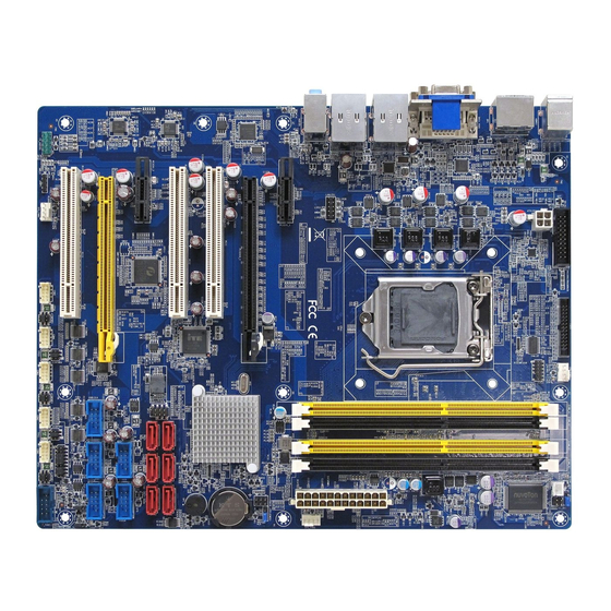
Page 18: Motherboard Layout
240-pin DDR3 DIMM Slot A1 DIMM_A2 240-pin DDR3 DIMM Slot A2 DIMM_B1 240-pin DDR3 DIMM Slot B1 DIMM_B2 240-pin DDR3 DIMM Slot B2 PCIEX16_1 PCI-e x16 Slot PCIEX4_1 PCI-e x4 Slot PCIEX1_1~2 PCI-e x1 Slot PCI1~3 PCI Slot 18 BC87Q User’s Manual... - Page 19 Amplifier Connector 4 x 1 header, pitch 2.54mm LANLED1 LAN LED header 5 x 2 header, pitch 2.54mm SATA1~6 Serial ATA Connectors 1~4 7-pin header USB34/78/910/1 USB 2.0 Connector 5 x 2 wafer, pitch 2.54mm 112/1314 BC87Q User’s Manual 19...
-
Page 20: Central Processing Unit (Cpu)
PnP cap is missing, or if you see any damage to the PnP cap/socket pins/motherboard components. BCM will shoulder the cost of repair only if the damage is shipment/transit-related. Keep the cap after installing the motherboard. BCM will process ... -
Page 21: Installing The Cpu
To prevent damage to the socket pins, do not remove the PnP cap unless you are installing a CPU. 3. Lift the Load lever with your thumb and forefinger to around 180º angle (A), then pull the BC87Q User’s Manual 21... - Page 22 (A) until it snaps into the retention tab. The CPU fits in only one correct orientation. DO NOT force the CPU into the socket to prevent bending the connectors on the socket and damaging the CPU! 22 BC87Q User’s Manual...
-
Page 23: Installing The Cpu Heatsink And Fan
Motherboard hole Orient the heatsink and fan assembly such that the CPU fan cable is closest to the CPU fan connector. Make sure each fastener is oriented as shown, with the narrow groove directed outward. BC87Q User’s Manual 23... - Page 24 These are not jumpers! DO NOT place jumper caps on the fan connectors. 1.4.3 Uninstalling the CPU Heatsink and Fan To uninstall the CPU heatsink and fan: 1. Disconnect the CPU fan cable from the connector on the motherboard. 2. Rotate each fastener counterclockwise 24 BC87Q User’s Manual...
- Page 25 BC87Q User’s Manual 3. Pull up two fasteners at a time in a diagonal sequence to disengage the heatsink and fan assembly from the motherboard. 4. Carefully remove the heatsink and fan assembly from the motherboard. BC87Q User’s Manual 25...
-
Page 26: System Memory
A DDR3 module has the same physical dimensions as a DDR DIMM but has a 240-pin footprint compared to the 240-pin DDR2 DIMM. DDR3 DIMMs are notched differently to prevent installation on a DDR2 DIMM socket. The following figure illustrates the location of the sockets: 240-Pin DDR3 DIMM sockets 26 BC87Q User’s Manual... -
Page 27: Memory Configurations
1. Unlock a DIMM socket by pressing the retaining clips outward 2. Alig3n a DIMM on the socket such that the notch on the DIMM matches the break on the socket BC87Q User’s Manual 27... - Page 28 DDR2 DIMMs to the DDR3 DIMM socket. Make sure to unplug the power supply before adding or removing DIMMs or other system components. Failure to do so may cause severe damage to both the motherboard and the components. 28 BC87Q User’s Manual...
-
Page 29: Removing A Dimm
In the future, you may need to install expansion cards. The following sub-sections describe the slots and the expansion cards that they support. Make sure to unplug the power cord before adding or removing expansion cards. Failure to do so may cause you physical injury and damage motherboard components. BC87Q User’s Manual 29... -
Page 30: Installing An Expansion Card
1.6.2.1 PCI Express x16 slot This motherboard supports one PCI Express x16 slot that complies with the PCI Express specifications. The following figure shows a graphics card installed on the PCI Express x16 slot. 1.6.2.2 PCI Express x 4 slot 30 BC87Q User’s Manual... -
Page 31: Pci Express X 1 Slot
The following figure shows an expansion card installed on the PCI Express x 1 slot. 1.6.2.4 PCI slot This motherboard supports one PCI slot that complies with the PCI specifications. The following figure shows a audio card installed on the PCI slot. BC87Q User’s Manual 31... -
Page 32: Jumpers
5~10 seconds, then move the cap back to pins 1-2. 4. Re-install the battery. 5. Plug the power cord and turn ON the computer. 6. Hold down the <Del> key during the boot process and enter BIOS setup to re-enter data. 32 BC87Q User’s Manual... -
Page 33: At/Atx Power Mode Select (Pson1)
(CPU Parameter Recall) feature. Shut down and reboot the system so the BIOS can automatically reset parameter settings to default values. 1.7.2 AT/ATX Power Mode Select (PSON1) This jumper allows you to select ATX Mode or AT mode . BC87Q User’s Manual 33... -
Page 34: Chassis Intrusion Connector (Jcase1)
BC87Q User’s Manual 1.7.3 Chassis Intrusion Connector (JCASE1) 1.7.4 COM1 RS232/ RS422/ RS485 Select (JSETCOM1) 34 BC87Q User’s Manual... -
Page 35: Com1, Com2, Com3, Com4, Com5 Ring-In/ +12V/ +5V Select (Jcompwr1, Jcompwr2, Jcompwr3, Jcompwr4, Jcompwr5)
1.7.5 COM1, COM2, COM3, COM4, COM5 Ring-In/ +12V/ +5V Select (JCOMPWR1, JCOMPWR2, JCOMPWR3, JCOMPWR4, JCOMPWR5) 1.8 Connectors 1.8.1 Rear panel connectors Item Name Function Description KBMS PS/2 Mouse The port is for a PS/2 mouse. Connector Display Port 2 VGA Video Port The VGA15-pin Connector. BC87Q User’s Manual 35... -
Page 36: Fan Connectors (Cpu_Fan1, Sys_Fan1, Sys_Fan2)
The fan connectors support cooling fans of 280mA (3.36 W max.) at 4800rpm or a total of 1A~2.22A (26.64W max.) at +12V. Connect the fan cables to the fan connectors on the motherboard, making sure that the black wire of each cable matches the ground pin of the connector. 36 BC87Q User’s Manual... -
Page 37: System Panel (F_Panel1)
1. GND SYS_FAN2 4. FAN_PWM3 3. FAN_SPEED3 2. +V12 1. GND 1.8.3 System Panel (F_PANEL1) This connector is for a chassis-mounted front panel audio I/O module that supports either HD Audio or legacy AC’97 audio standard. BC87Q User’s Manual 37... -
Page 38: Atx Power Connectors (Eatxpwr1 (24-Pin), Atx12V1 (4-Pin))
1.8.4 ATX power connectors (EATXPWR1 (24-Pin), ATX12V1 (4-pin)) The connector is for ATX power supply plugs. The power supply plugs are designed to fit these connectors in only one orientation. Find the proper orientation and push down firmly until the connectors completely fit. 38 BC87Q User’s Manual... -
Page 39: Serial Port Connectors (Com1, Com2, Com3, Com4, Com5)
1.8.5 Serial Port connectors (COM1, COM2, COM3, COM4, COM5) This connector is for a serial (COM) port. Connect the serial port module cable to this connector, then install the module to a slot opening at the back of the system chassis. BC87Q User’s Manual 39... -
Page 40: Digital Io Connector (Jdio1)
BC87Q User’s Manual 1.8.6 Digital IO Connector (JDIO1) This connector is for 8-bit General purpose I/O function. 1.8.7 PARALLEL PORT Connector (LPT2) 40 BC87Q User’s Manual... -
Page 41: Audio Mic.-In & Line-Out Connector (Fp_Audio1)
Audio or legacy AC ‘97 (optional) audio standard. For motherboards with the optional HD Audio feature, we recommend that you connect a high-definition front panel audio module to this connector to avail of the motherboard’s high‑definition audio capability. 1.8.9 Amplifier Connector (JAMP1) BC87Q User’s Manual 41... -
Page 42: Lan Led Header (Lanled_1)
4. GND 3. GND 2. LAN1_ACT 1. LAN1_ACT 1.8.11 Serial ATA Connector (SATA1, SATA2, SATA3, SATA4, SATA5, SATA6) These connectors support SATA 3.0 and are for the Serial ATA signal cables for Serial ATA hard disk drives. 42 BC87Q User’s Manual... -
Page 43: Front Usb Headers: Usb34, Usb78, Usb910, Usb1112, Usb1314
These connectors are for USB 2.0 ports. Connect the optional USB module cable to any of these connectors, then install the module to a slot opening at the back of the system chassis. These USB connectors comply with USB 2.0 specification that supports up to 480 Mbps connection speed. BC87Q User’s Manual 43... -
Page 44: Pc Ok Connector (Pc_Ok1)
BC87Q User’s Manual 1.8.13 PC OK Connector (PC_OK1) 1.8.14 RAID LED Connector (RAID_LED1) 44 BC87Q User’s Manual... - Page 45 BC87Q User’s Manual This chapter tells how to change the system settings through the BIOS Setup menus. Detailed descriptions of the BIOS parameters are also provided. BC87Q User’s Manual 45...
-
Page 46: Bios Setup Program
The BIOS setup screens shown in this section are for reference purposes only, and may not exactly match what you see on your screen. Visit the system builder’s website to download the latest BIOS file for this motherboard 46 BC87Q User’s Manual... -
Page 47: Legend Box
To access the menu items, press the up/down/right/left arrow key on the keyboard until the desired item is highlighted, then press [Enter] to open the specific menu. BC87Q User’s Manual 47... -
Page 48: Main Setup
BC87Q User’s Manual 2.3 Main Setup This menu gives you an overview of the general system specifications. The BIOS automatically detects the items in this menu. Use this menu for basic system configurations, such as time, date etc. 48 BC87Q User’s Manual... - Page 49 BC87Q User’s Manual BIOS Information Displays the auto-detected BIOS information. System Date The date format is <Date>,<Month>,<Day>,<Year>. System Time The time format is <Hour>,<Minute>,<Second>. BC87Q User’s Manual 49...
-
Page 50: Advanced Bios Setup
The Advanced BIOS Setup screen is shown below. The sub menus are described on the following pages. Take caution when changing the settings of the Advanced menu items. Incorrect field values can cause the system to malfunction. 50 BC87Q User’s Manual... -
Page 51: Pci Subsystem Setting
Value to be programmed into PCI Latency Timer Register Configuration options: [32 PCI Bus Clocks] [64 PCI Bus Clocks] [96 PCI Bus Clocks] [128 PCI Bus Clocks] [160 PCI Bus Clocks] [192 PCI Bus Clocks] [224 PCI Bus Clocks] [248 PCI Bus Clocks] BC87Q User’s Manual 51... -
Page 52: Acpi Settings
Control PCI/PCIE wake up function Configuration options: [Disabled] [Enabled] Resume On RTC Alarm [Disabled] Enable or disable system wake on alarm even. When enabled, system will wake upon the hr/min/sec specified. Configuration options: [Disabled] [Enabled] 52 BC87Q User’s Manual... -
Page 53: Trusted Computing
BC87Q User’s Manual 2.4.3 Trusted computing Trusted computing (TPM) settings. Configuration Security Device Support [Disabled] Enable or disable TPM support. Configuration options: [Disabled] [Enabled] Current Status Information Displays the TPM status information BC87Q User’s Manual 53... -
Page 54: Cpu Configuration
Enabled or disabled Hyper-Treading Technology Configuration options: [Disabled] [Enabled] Active Processor Cores [All] Select the numbers of cores in each processor package. Configuration options: [All] [1] [2] [3] [4] [5] [6] [7] It depends on each CPU type. 54 BC87Q User’s Manual... - Page 55 Turbo Mode[Enabled] Enable or Disable CPU Turbo Mode. Configuration options: [Disabled] [Enabled] CPU C States [Enabled] Enable or Disable CPU C states Configuration options: [Disabled] [Enabled] Enhanced C1 state [Enabled] Enhanced C1 state BC87Q User’s Manual 55...
- Page 56 Package C State limit [AUTO] Package C State limit. Configuration options: [C0/C1] [C2] [C3] [C6] [C7] [C7s] [AUTO] Intel TXT(LT) Support [Disabled] Enable or disable Intel TXT(LT) support. Configuration options: [Disabled] [Enabled] 56 BC87Q User’s Manual...
-
Page 57: Sata Configuration
BC87Q User’s Manual 2.4.5 SATA Configuration Serial-ATA Controller(s) [Enable] Enabled/Disabled Serial-ATA Controller 0 Configuration options: [Disabled] [Enabled] SATA Mode [IDE] Determines how SATA controller(s) operate. Configuration options: [IDE][AHCI][RAID] BC87Q User’s Manual 57... -
Page 58: Pch-Fw Configuration
BC87Q User’s Manual 2.4.6 PCH-FW Configuration Display ME firmware information 58 BC87Q User’s Manual... -
Page 59: Amt Configuration
BC87Q User’s Manual 2.4.7 AMT Configuration Intel AMT [Enabled] Enable/Disable Intel Active Management Technology. Configuration options: [Disabled] [Enabled] Un-Configure ME [Disabled] Un-Configure ME without password. Configuration options: [Disabled] [Enabled] BC87Q User’s Manual 59... -
Page 60: Usb Configuration
Display how many devices are connected. Legacy USB Support [Enabled] Enables Legacy USB support. AUTO option disables legacy support if no USB devices are connected. DISABLE option will keep USB devices available only for EFI applications. Configuration options: [Enabled] [Disabled][Auto] 60 BC87Q User’s Manual... -
Page 61: Super Io Configuration
BC87Q User’s Manual 2.4.9 Super IO Configuration System Super IO Chip Parameters. BC87Q User’s Manual 61... - Page 62 Configuration options: [Auto] [IO=3F8h; IRQ=4] [IO=3F8h; IRQ=3, 4, 5, 6, 7, 9. 10, 11, 12] [IO=2F8h; IRQ=3, 4, 5, 6, 7, 9. 10, 11, 12] [IO=3E8h; IRQ=3, 4, 5, 6, 7, 9. 10, 11, 12] [IO=2E8h; IRQ=3, 4, 5, 6, 7, 9. 10, 11, 12] 62 BC87Q User’s Manual...
- Page 63 Configuration options: [Disabled] [Enabled] Device Setting [IO=3E8h; IRQ=5] Change Setting[Auto] Select an optimal setting for Super IO device. Configuration options: [Auto] [IO=3E8h; IRQ=5] [IO=3F8h; IRQ=5, 10] [IO=2F8h; IRQ=5, 10] [IO=3E8h; IRQ=5, 10] [IO=2E8h; IRQ=5, 10] BC87Q User’s Manual 63...
- Page 64 Configuration options: [Disabled] [Enabled] Device Setting [IO=2E8h; IRQ=5] Change Setting[Auto] Select an optimal setting for Super IO device. Configuration options: [Auto] [IO=2E8h; IRQ=5] [IO=3F8h; IRQ=5, 10] [IO=2F8h; IRQ=5, 10] [IO=3E8h; IRQ=5, 10] [IO=2E8h; IRQ=5, 10] 64 BC87Q User’s Manual...
- Page 65 Device Setting [IO=2E0h; IRQ=10] Change Setting[Auto] Select an optimal setting for Super IO device. Configuration options: [Auto] [IO=2E0h; IRQ=10] [IO=3F8h; IRQ=5, 10] [IO=2F8h; IRQ=5, 10] [IO=3E8h; IRQ=5, 10] [IO=2E8h; IRQ=5, 10] [IO=2E0h; IRQ=5, 10] [IO=2F0h; IRQ=5, 10] BC87Q User’s Manual 65...
- Page 66 Device Setting [IO=2F0h; IRQ=10] Change Setting[Auto] Select an optimal setting for Super IO device. Configuration options: [Auto] [IO=2F0h; IRQ=10] [IO=3F8h; IRQ=5, 10] [IO=2F8h; IRQ=5, 10] [IO=3E8h; IRQ=5, 10] [IO=2E8h; IRQ=5, 10] [IO=2E0h; IRQ=5, 10] [IO=2F0h; IRQ=5, 10] 66 BC87Q User’s Manual...
- Page 67 Use this item to change the Printer Port mode. Configuration Options: [STD Printer Mode] [SPP Mode] [EPP-1.9 and SPP Mode] [EPP-1.7 and SPP Mode] [ECP Mode] [ECP Mode and EPP-1.9 Mode] [ECP Mode and EPP-1.7 Mode] BC87Q User’s Manual 67...
- Page 68 Configuration options: [Second(s) Mode [Minute(s) Mode] WatchDog TimeOut Value [0] Timer will start to count from end of POST. 00 – Timeout Disable GPIO Group Control [Disabled] Configure the digital GPIO pins. Configuration options: [Disabled] [Enabled] 68 BC87Q User’s Manual...
-
Page 69: H/W Monitor
BC87Q User’s Manual 2.4.10 H/W Monitor PC Health Status Display system health status BC87Q User’s Manual 69... - Page 70 BC87Q User’s Manual 2.4.10.1 Smart Fan Smart Fan Function [Enable] Smart Fan Function enable/disable Configuration options: [Disabled] [Enabled] 70 BC87Q User’s Manual...
- Page 71 Configuration options: [Disabled] [40 C] [45 C] [50 C] [55 C] [60 C] [65 C] [70 C] CPU Smart Fan Target [Disabled] CPU Smart Fan Target Temperature Configuration options: [Disabled] [40 C] [45 C] [50 C] [55 C] [60 C] [65 C] [70 C] BC87Q User’s Manual 71...
-
Page 72: Option Rom Policy
Enable or Disable Boot Option For Legacy Mass Storage Devices with Option ROM Configuration options: [Do not launch] [UEFI only] [Legacy only] Other PCI Device ROM priority [UEFI OpROM] Configuration options: [UEFI OpROM] [Legacy OpROM] 72 BC87Q User’s Manual... -
Page 73: Intel Rc Driver Version Detail
BC87Q User’s Manual 2.4.12 Intel RC Driver Version Detail Displays Version String for drivers BC87Q User’s Manual 73... -
Page 74: Chipset
BC87Q User’s Manual 2.5 Chipset 74 BC87Q User’s Manual... -
Page 75: Pch-Io Configuration
Enable/Disable LAN1 boot option for legacy network devices. Configuration options: [Disabled] [Enabled] LAN2 Controller [Enable] Enable/Disable LAN1 Controller Configuration options: [Disabled] [Enabled] LAN2 Option-ROM [Disable] Enable/Disable LAN2 boot option for legacy network devices. Configuration options: [Disabled] [Enabled] BC87Q User’s Manual 75... - Page 76 BC87Q User’s Manual Restore AC Power Loss [Always Off] Specify what state to go to when power is re-applied after a power failure. Configuration options: [Always Off] [Always On] [Last state] 76 BC87Q User’s Manual...
- Page 77 BC87Q User’s Manual 2.5.1.1 PCI Express Configuration BC87Q User’s Manual 77...
- Page 78 PCIe Speed [Auto] Select PCI Express port speed. Configuration options: [AUTO] [Gen1] [Gen2] Detect Non-Compliance Device [Disabled] Detect Non-Compliance PCI Express Device. If enable, it will take more time at POST time Configuration options: [Disabled] [Enabled] 78 BC87Q User’s Manual...
- Page 79 PCIe Speed [Auto] Select PCI Express port speed. Configuration options: [AUTO] [Gen1] [Gen2] Detect Non-Compliance Device [Disabled] Detect Non-Compliance PCI Express Device. If enable, it will take more time at POST time Configuration options: [Disabled] [Enabled] BC87Q User’s Manual 79...
- Page 80 BC87Q User’s Manual 2.5.1.2 USB Configuration USB3.0 Support [Enabled] Enable/Disable USB 3.0 support Configuration options: [Disabled] [Enabled] USB ports per-port disable cont [Disabled] Control each of the USB ports (1~14) disabling. Configuration options: [Disabled] [Enabled] 80 BC87Q User’s Manual...
- Page 81 BC87Q User’s Manual 2.5.1.3 PCH Azalia Configuration Azalia [Enabled] Control Detection of the Azalia device. Configuration options: [Disabled] [Enabled] BC87Q User’s Manual 81...
-
Page 82: System Agent (Sa) Configuration
BC87Q User’s Manual 2.5.2 System Agent (SA) Configuration VT-d [Disable] Set VT-d Enable or Disable Configuration options: [Disabled] [Enabled] 82 BC87Q User’s Manual... - Page 83 Select DVMT 5.0 Pre-Allocated (Fixed) graphics memory size used by the internal graphics device. Configuration options: [32M]~[512M] DVMT Total Gfx Mem [256M] Select DVMT 5.0 total graphics memory size used by the internal graphics device. Configuration options: [128M][256M][MAX] BC87Q User’s Manual 83...
- Page 84 BC87Q User’s Manual 2.5.2.1.1 LCD Control Primary IGFX Boot Display [VBIOS Default] Select the Video Device that will be activated during POST. Configuration options: [VBIOS Default] [CRT] [Display Port1] [DVI-D] [Display Port2] 84 BC87Q User’s Manual...
- Page 85 Configuration options: [Disabled] [Enabled] PEG1 - ASPM [Disabled] Control ASPM support for the PEG Device. This has no effect if PEG is not the currently active device. Configuration options: [Disabled] [Auto] [ASPM L0s] [ASPM L1] [ASPM L0sL1] BC87Q User’s Manual 85...
- Page 86 BC87Q User’s Manual 2.5.2.3 Memory Information Display Memory Information 86 BC87Q User’s Manual...
-
Page 87: Boot
Select the keyboard NumLock state Configuration options: [On] [Off] Quiet Boot [Disabled] Enables or disables Quiet Boot option. Configuration options: [Disabled] [Enabled] Boot mode select [LEGACY] Select boot mode LEGACY/UEFI. Configuration options: [LEGACY] [UEFI] BC87Q User’s Manual 87... -
Page 88: Security
BC87Q User’s Manual 2.7 Security Administrator Password Set setup Administrator Password User Password Set User Password 88 BC87Q User’s Manual... -
Page 89: Save & Exit
Discard changes and Exit Exit system setup without saving the changes. Save changes and Reset Reset the system after saving the changes. Load Optimized Defaults Restore/Load default values for all the setup option. BC87Q User’s Manual 89...
Need help?
Do you have a question about the BC87Q and is the answer not in the manual?
Questions and answers