Table of Contents
Advertisement
Quick Links
Intel® C246 ATX Motherboard supports LGA1151 Coffee Lake/Coffee Lake
User's Quick Start Card
• Inspect the Package:
One
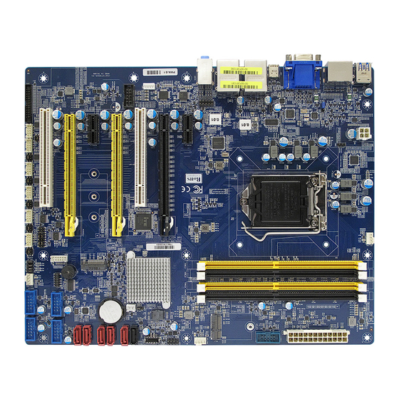
BC246C Motherboard
One
I/O Shield
• Responsibility:
This manual is provided "As-Is" with no warranties of any kind, it will neither expressed or implied,
including, but not limited to the implied warranties or conditions of this product's fitness for any
particular purpose. In no event shall we be liable for any loss of profits, loss of business, loss of data,
interruption of business, or indirect, special, incidental, or consequential damages of any kind, even
the possibility of such damages arising from any defect or error in this manual or product. We reserve
the right to modify and update the user manual without prior notice.
WARNING: CMOS Battery Damage
Replace your system's CMOS RAM battery only with the identical CR-2032 3V Lithium-Ion coin cell
(or equivalent) battery type to avoid risk of personal injury or physical damage to your equipment.
Always dispose of used batteries according to the manufacturer's instructions, or as required by the
local ordinance (where applicable). The damage due to not following this warning will void your
motherboard's manufacturer warranty.
Perchlorate Material- Special Handling May Apply.
See
http://www.dtsc.ca.gov/hazardouswaste/perchlorate/
ATTENTION: Incorrect BIOS Setup
If you do not know how to handle BIOS setup or how to set it up properly, it is strongly advisable that
you do not modify any of the settings than otherwise instructed in the User's Quick Start Card. Even
a seemingly small incorrect adjustment or modification in the BIOS setup can render your system
unstable or unusable. The incorrect BIOS setup is not covered by your motherboard's manufacturer
warranty.
• Additional Information:
Additional information on setting this board up can be found in the User's Manual in the provided CD-
ROM. The Online User's Manual and FAQ/Knowledge Base can be found on our website by visiting
our website: http://www.bcmcom.com. If your question is not answered in our FAQ/Knowledge
Base, visit our forums and post your messages or submit a new FAQ through FAQ Submittal form for
us to add your question in our FAQ with our answer.
BC246C
Refresh Core and Xeon CPU
ATX Motherboard
Version 1.0
http://www.bcmcom.com
Advertisement
Table of Contents

Subscribe to Our Youtube Channel
Related Manuals for BCM BC246C


Summary of Contents for BCM BC246C
- Page 1 User’s Quick Start Card http://www.bcmcom.com Version 1.0 • Inspect the Package: BC246C Motherboard I/O Shield • Responsibility: This manual is provided “As-Is” with no warranties of any kind, it will neither expressed or implied, including, but not limited to the implied warranties or conditions of this product’s fitness for any particular purpose.
-
Page 2: Motherboard Layout
WARNING: Electrostatic Sensitive Device (ESD) Static electricity can easily damage your motherboard and will void your motherboard warranty. Keep the motherboard and other system components in their anti-static packaging until you are ready to install them. Touch a grounded surface before you remove any system component from its protective anti-static packaging. - Page 3 • Back Panel: Item Name Function Description USB1516 USB 3.1 Gen2 These two Universal Serial Bus (USB) ports are Port available for connecting USB 3.1 devices. Display Port These two display port Connectors are available for connecting display port devices. VGA Port The VGA port Connector HDMI...
- Page 4 USB34 USB 3.0 These two 4-pin Universal Serial Bus (USB) ports Connectors are available for connecting USB 3.1 devices. AUDIO1 Line-in port This port connects a tape, CD, DVD player, or (Light blue) other audio sources. AUDIO1 Line-out port This port connects a headphone or a speaker. In (Lime) 4-channel, 6-channel, and 8-channel configuration, the function of this port becomes...
- Page 5 Jumpers, Connectors, & Headers: • Clear CMOS Jumper: CLCMOS1 Normal (Default) Clear CMOS • ATX/AT Mode Selection: JPSON1 AT mode ATX mode (Default)
- Page 6 • COM POWER SETTING (JCOMPWR1~6) Ring +12V •COM1 Master/Slave terminal Setting (COM1_S1~4)
- Page 7 •COM1 type Setting (JSETCOM1) •LPT Port Connector (LPT1) 1. LPT_STB# 2. LPT_AFD# 3. LPT_PD0 4. LPT_ERR# 5. LPT_PD1 6. LPT_INIT# 7. LPT_PD2 8. LPT_SLIN# 9. LPT_PD3 10. GND 11. LPT_PD4 12. GND 13. LPT_PD5 14. GND 15. LPT_PD6 16. GND 17.
-
Page 8: Atx Power Connectors: Eatxpwr1 & Atx12V1
• ATX Power Connectors: EATXPWR1 & ATX12V1 ATX12V1 ATX12V1 EATXPWR1 EATXPWR1 Fan Connectors: CPU_FAN1, CHA_FAN1, CHA_FAN2 CPU_FAN1 4. FAN_PWM1 3. FAN_SPEED2 2. +V12 1. GND CHA_FAN1 4. FAN_PWM2 3. FAN_SPEED2 2. +V12 1. GND CHA_FAN2 4. FAN_PWM3 3. FAN_SPEED3 2. +V12 1. -
Page 9: Serial Port Connectors: Com1
• Serial Port Connectors: COM1~6 1. DCD# 2. RX 3. TX 4. DTR# 5. GND 6. DSR# 7. RTS# 8. CTS# 9. RI3xPOWERxJMP • SATA 3.0 Ports: SATA1~6 SATA 1. GND 2. TX+ 3. TX- 4. GND 5. RX- 6. RX+ 7. - Page 10 • Front USB 3.1 Headers: USB56 1.GND 2. TX+ 3. TX- 4. GND 5. RX+ 6. RX- 7. GND 8. CM+ 9. CM- 10. USB VCC 11. GND 12. TX- 13. TX+ 14. GND 15. RX- 16. RX+ 17. GND 18.
- Page 11 • Front Panel Connector: F_PANEL1 1. HDD LED+ 2. +5VSB 3. HDD LED# 4. PWR LED# 5. GND 6. PANSWIN# 7. RST 8. GND 9. N/A • Front Panel Audio Connector: FP_AUDIO1 FP_AUDIO1 9. LINE2L 10. LINE2-JD 7. SENSEB 8. NC 6.
-
Page 12: Amplifier Connector: Jamp1
• Amplifier Connector: JAMP1 JAMP1 1. AMP_L- 2. AMP_L+ 3. AMP_R- 4. AMP_R+ • Digital I/O Connector: JDIO1 1. SIO_GPIO0 2. SIO_GPIO4 3. SIO_GPIO1 4. SIO_GPIO5 5. SIO_GPIO2 6. SIO_GPIO6 7. SIO_GPIO3 8. SIO_GPIO7 9. SMB_CLK_ 10. SMB_DATA_ RESUME RESUME 11. - Page 13 •SM bus connector (JSMB1) 1. SMBCLK 2. SMBDATA 3. GND •Chassis Intrusion Connector: JCASE1 1. SIO_CASEOPEN# 2. GND...
Need help?
Do you have a question about the BC246C and is the answer not in the manual?
Questions and answers