Lincoln Electric GMA WIRE FEEDERS LN-7 Operator's Manual
Wire feeders (2 and 4 roll models)
Hide thumbs
Also See for GMA WIRE FEEDERS LN-7:
- Operating manual (29 pages) ,
- Technical specifications (8 pages) ,
- Service manual (129 pages)
Table of Contents
Advertisement
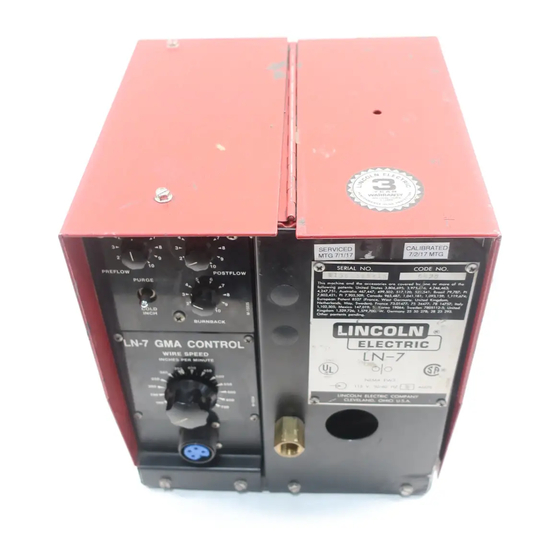
LN-7 and LN-7 GMA Wire Feeders
Safety Depends on You
Lincoln arc welding and cutting
equipment is designed and built
with safety in mind. However, your
overall safety can be increased by
proper installation ... and thought-
ful operation on your part. DO
NOT INSTALL, OPERATE OR
REPAIR THIS EQUIPMENT
WITHOUT
READING
THIS
MANUAL AND THE SAFETY
PRECAUTIONS CONTAINED
THROUGHOUT. And, most
importantly, think before you act
and be careful.
LN-7 GMA shown with optional
K417 digital meter kit and K418
GMA timer kit.
• Sales and Service through Subsidiaries and Distributors Worldwide •
Cleveland, Ohio 44117-1199 U.S.A. TEL: 216.481.8100 FAX: 216.486.1751 WEB SITE: www.lincolnelectric.com
RETURN TO MAIN MENU
(2 and 4 Roll Models)
For machines with code numbers: 9100 and above
L N
- 7
G M
A C
W I
O N
R E
IN
C H
S P
T R
E S
E E
P E
D
R
3 0
3 5
0
M IN
0
2 5
4 0
0
U T
0
E
4 5
2 0
0
0
5 0
1 5
0
0
1 0
5 5
0
0
6 0
0
6 5
0
7 0
0
OPERATOR'S MANUAL
• World's Leader in Welding and Cutting Products •
S E
R I
T h
A L
is
fo ll
m a
o w
N O
c h
4 ,2
in g
in e
.
4 7
p a
7 ,8
,7 5
a n
0 3
te n
d th
1 ;
E u
,4 2
ts :
e a
A u
ro p
1 ;
U n
c c
N e
P I
s tr
th e
e a
a li
it e
e s
n P
7 ,9
a 4
d s
s o
1 ,1
rl a
a te
0 5
6 7
ta te
ri e
K in
0 2
n d
s a
C O
,5 0
s ,
n t
,5 0
,4 4
g d
s 3
re
O th
2 ;
It a
8 5
9 ;
7 ;
,8 0
D E
o m
ly ,
2 7
C a
4 9
c o
e r
M e
6 ,6
v e
1 ,5
S w
(F ra
n a
9 ,5
N O
p a
x ic
9 5
re d
te n
2 9
o 1
e d
d a
0 2
n c
9 6
; 5
; 3
b y
.
ts
,7 2
4 7
e n
e ,
.9 7
); F
5 ,4
1 7
o n
p e
6 ;
,0 1
W
5 ,6
n d
1 ,5
ra n
e s
8 7
,1 2
e o
9 ;
; 1
1 6
r m
in g
7 9
S .
c e
t G
0 ;
e rm
,0 4
5 2
; 4
o re
.
,7 0
K o
7 3
,2 4
1 ,1
5 ,5
0 ;
re a
.0 1
a n
6 ,4
o f
W .
y ,
8 1
4 1
th e
O L
1 9
4 7
; 1
; B
6 3
G e
7 ;
U n
0 6
,0 9
ra z
;
rm
4 ;
7 5
it e
d K
3 ,1
il 7
a n
S w
3 4
y 2
4 7
in g
5 9
9 ,7
e d
; 1
8 7
5 5
e n
7 ;
d o
7 8
,1 1
; P
0 2
7 8
m ,
1 4
9 ,6
I
7 8
0 5
1 1
7 5
7 4
; 2
7 l
;
8 2
2 -5
It a
3 2
; U
ly
9 3
n it
e d
.
L N
- 7
N E
1 1
M A
5 V
, 5
E W
0 / 6
3
0 H
Z
A M
P S
Copyright © Lincoln Global Inc.
IM351-C
June, 2010
.
R S
H E
O T
&
L F
S E
U R
b e
Y O
n
c a
E C
T
h
S
a lt
O T
S E
h e
P R
G A
th ,
d
G ,
u r
bo
e an
y o
or
N IN
D
c,
g w
on
A N
ar
th in
A R
s to
th e
W
S
.
t at
ea
M E
o u
es
us
br
u s
e
IS
e r
fu m
ha
yo
ur
T H
F U
t of
ex
m
c a
A D
n g
ou
n or
s fro
d a
n
R E
he
ad
nt ila
tio
se
c a
ur
d ga
p yo
ve
an
K S
gh
es
le
K ee
ou
fu m
.
A R
ab
en
ea
n .
m m
U se
ep
l ar
S P
fla
to
ke
ra
s io
ia l.
ld
d
ne
G
er
he
a n
ge
D IN
lo
m at
ve
x p
le
ha
e s
G
E L
ab
w hi
ch
r e
m m
e y
e o
fla
rs
D E
W
ar
nt ai
ne
r e
D E
I N
fi r
ne
ju
E S
el d
co
Q U
N E
t w
on
in
Z O
N .
no
el d
n
R IS
D o
t w
c a
S
L A
A T
IO
no
ia l
D E
N IS
ty ,
R N
D o
er
Y S
n
IL IS
m at
R A
tio
T E
D A
U T
c ie
.
ot ec
O R
S
n t
in
pr
M P
N E
A N
T
S o
C
s k
dy
O N
m e
A R
d bo
C O
A V
in g
9 6
l
r n
R C
R S
U E
e rn
k il
w
ith
b u
r an
P E
e ld
o v
6 1
W A
d e
e ea
L' A
S
N IQ
M 1
c a
n
A
L E
C H
n W
. G
ct
ro
r ey
E
O U
T E
U .S
e le
o rk
ea
U R
c a
V M
K
o r
w
W
U D
U R
E
e ri
O C
s
d .
o r
T E
T IC
m
a rt
u n
s
S O
R A
N O
A m
fr o
S H
l p
g ro
ve
d e
L A
g lo
si
P E
L A
e
b le
IC
ri ca
a n
d
s.
g ,
in
T:
L' O
E R
th
a ila
T R
ct
ve
in
o r
e r.
E N
b y
e le
o rk
g lo
o th
e r
e ld
E M
P U
R
S U
LT
A v
E C
e
g
w
g
cl
n d
) w
T IS
e d
o th
liv
in
m
tin
u r
, u
ir e
E S
O N
s h
1 0
E L
u ch
fr o
la
o n
E R
S R
. C
b li
1 9
e t
cl
e lf
su
if
yo
g
(w
A V
E S
t to
w
u rs
in
e r
in
g e
A IL
p u
R
n o
o r
ry
e ld
o rk
lta
B L
A V
C F
o
yo
r d
w
w
e n
t:
t vo
o l.
T R
g ",
D
in
te
e a
A C
o r
if
a n
n tr
,
2 9
sk
la
w
u ip
m
T H
IS
N S
tt in
s ,
G
su
a ys
se
p
e q
n st
g e
co
T S
C u
N IN
In
t u
d a
m
co
e r
d
g .
E
C T
IO
a rd
A lw
n o
.
g
C
e ld
lta
o ve
in
R V
IC
E E
d
n d
A R
o
is
ce
w
in
D
w
vo
m
rv
ic
R U
S H
a n
D
a re
a
p la
llo
a tic
d
re
se
S E
S T
T A
S ta
W
o rk
fo
k)
d u
ce
ls
O F
in g
w
e
u to
m
l (s
tic
n e
fo
re
IN
D A
th
IS
th
u a
re
p a
b e
S E
E 'S
Y
e ld
e a
T H
se
m
ia
a n
ith
e r
, U
U R
E T
d H
U
S e
e r
w
w
ith
o w
L L
C T
A F
W
V E
M
te
t p
F A
L S
in
a n
D
C
e ld
ra
p u
S TA
M O
w
p e
IN
N U
R IA
ty
fe ty
A c
t o
in
L D
M A
T E
a fe
R E
n o
e ct
M A
S a
o
n n
O U
T H
E
"S
T
D
co
S H
D
.1
H A
N O
is
A L
O W
A N
4 9
D
L L
E S
O S
O
O N
Z
6 ;
. D
R S
F O
T IC
P E
D
A C
a rd
1 2
0 2
A N
P R
S .
n d
3 3
D
A D
L E
0 4
IE
T Y
A B
S ta
d a
. 2
A L
IF
R E
F E
a l
lo ri
S A
U M
D .C
Q U
N T.
N S
o n
i, F
M E
'S
C O
a ti
n ,
O N
LY
E R
ia m
U IP
O Y
R
n N
g to
E Q
P L
F O
., M
h in
S )
c a
R d
E M
S D
e ri
a s
n e
(M
A m
, W
e u
ic e
e
e J
S e
O ff
0 L
n g
5 5
n ti
P ri
Advertisement
Table of Contents

Related Manuals for Lincoln Electric GMA WIRE FEEDERS LN-7


Summary of Contents for Lincoln Electric GMA WIRE FEEDERS LN-7
- Page 1 LN-7 and LN-7 GMA Wire Feeders (2 and 4 Roll Models) For machines with code numbers: 9100 and above Safety Depends on You Lincoln arc welding and cutting equipment is designed and built with safety in mind. However, your overall safety can be increased by proper installation ...
- Page 6 Thank You...
-
Page 7: Table Of Contents
TABLE OF CONTENTS Safety ............Installation . -
Page 8: Technical Specifications
TECHNICAL SPECIFICATIONS – LN-7 and LN-7 GMA Supplied by power source: 115 VAC, 50/60 Hz, 2.5 Amps LN-7 GMA LN-7 LN-7 GMA LN-7 WITHOUT WIRE STAND ROLL WITH WIRE FEEDER STAND (K377) WITHOUT FOUR WIRE STAND ROLL FEEDER WITH WIRE STAND (K377) DUTY CYCLE: The amount of welding performed in a 10 minute period, expressed as a percentage. -
Page 9: Mounting Location
Control - Connection Diagram LN-7 GMA To CV/CVI Power Source (K867/K775) - Connection Diagram LN-7 GMA To R3S-250 or R3S-325 - Connection Diagram LN-7 GMA To SAM Motor Generator or Engine Welder - Connection Diagram A.10 LN-7 GMA To DC-600 - Connection Diagram A.11... - Page 10 1. For K291 and K404 cables, connect the end of the control cable with the lugged leads to the power source. If lead #21 is extended to work, do not connect leads to terminal #21 on terminal strip. For K584, K594 or K480 cables connect the 14 pin amphenol connector to the power source.
- Page 11 5. Connect the input control cable polarized Amphenol plug into the mating 6-pin receptacle on the rear of the control section. 6. Referring to Figure A.2, install the input cable under the wire reel mounting stand strain relief INSTALLATION clamp. Remove the screws holding the clamp to the base of the wire reel mounting assembly, put the input cable assembly under the clamp and reinstall the screws.
- Page 12 FIGURE A.3 – LN-7 & LN-7 GMA TO DC-400, DC-250 AND CV/CVI POWER SOURCES WITH TERMINAL STRIP - CONNECTION DIAGRAM. – INSTALLATION TURN INPUT POWER OFF WARNING BEFORE CONNECTING THE LN-7 GMA WIRE FEEDER. ELECTRIC SHOCK CAN KILL CLEVELAND, OHIO U.S.A LN-7 &...
- Page 13 FIGURE A.4 – LN-7 & LN-7 GMA TO PULSED POWER 500 - CONNECTION DIAGRAM. – INSTALLATION TURN INPUT POWER OFF WARNING BEFORE CONNECTING THE LN-7 GMA WIRE FEEDER. ELECTRIC SHOCK CAN KILL CLEVELAND, OHIO U.S.A LN-7 & LN-7 GMA...
- Page 14 INSTALLATION FIGURE A.5 – LN-7 & LN-7 GMA TO CV/CVI POWER SOURCES WITH 14 PIN AMPHENOL CONNECTOR - CONNECTION DIAGRAM. TURN INPUT POWER OFF WARNING BEFORE CONNECTING THE LN-7 GMA WIRE FEEDER. ELECTRIC SHOCK CAN KILL – CLEVELAND, OHIO U.S.A LN-7 &...
- Page 15 FIGURE A.6 – LN-7 & LN-7 GMA TO CV/CVI POWER SOURCES WITH TWIST-MATE CONNECTOR AND 14 PIN AMPHENOL/REMOTE CONTROL - CONNECTION DIAGRAM. – INSTALLATION TURN OFF INPUT POWER WARNING TO THE WELDING POWER SOURCE USING THE DISCONNECT SWITCH AT THE FUSE BOX BEFORE CONNECTING THE WIRE FEEDER.
- Page 16 INSTALLATION FIGURE A.7 – LN-7 & LN-7 GMA TO CV/CVI POWER SOURCE (K867/K775) - CONNECTION DIAGRAM. TURN INPUT POWER OFF WARNING BEFORE CONNECTING THE LN-7 GMA WIRE FEEDER. ELECTRIC SHOCK CAN KILL – CLEVELAND, OHIO U.S.A LN-7 & LN-7 GMA...
- Page 17 A-10 A-10 INSTALLATION FIGURE A.8 – LN-7 & LN-7 GMA TO R3S-250 OR R3S-325 - CONNECTION DIAGRAM. TURN INPUT POWER OFF WARNING BEFORE CONNECTING THE LN-7 GMA WIRE FEEDER. ELECTRIC SHOCK CAN KILL – CLEVELAND, OHIO U.S.A LN-7 & LN-7 GMA...
- Page 18 A-11 FIGURE A.9 – LN-7 & LN-7 GMA TO SAM MOTOR GENERATOR OR ENGINE WELDER - CONNECTION INSTALLATION DIAGRAM. TURN INPUT POWER OFF WARNING BEFORE CONNECTING THE LN-7 GMA WIRE FEEDER. ELECTRIC SHOCK CAN KILL CLEVELAND, OHIO U.S.A LN-7 & LN-7 GMA...
- Page 19 A-12 A-12 INSTALLATION FIGURE A.10 – LN-7 & LN-7 GMA TO DC-600 - CONNECTION DIAGRAM. TURN INPUT POWER OFF WARNING BEFORE CONNECTING THE LN-7 GMA WIRE FEEDER. ELECTRIC SHOCK CAN KILL – CLEVELAND, OHIO U.S.A LN-7 & LN-7 GMA...
- Page 20 A-13 FIGURE A.11 – LN-7 & LN-7 GMA TO R3S-400, 600, OR 800 - CONNECTION DIAGRAM. INSTALLATION TURN INPUT POWER OFF WARNING BEFORE CONNECTING THE LN-7 GMA WIRE FEEDER. ELECTRIC SHOCK CAN KILL CLEVELAND, OHIO U.S.A LN-7 & LN-7 GMA A-13...
- Page 21 A-14 FIGURE A.12 – LN-7 & LN-7 GMA TO MOST LINCOLN MOTOR GENERATORS - CONNECTION DIAGRAM. INSTALLATION TURN INPUT POWER OFF WARNING BEFORE CONNECTING THE LN-7 GMA WIRE FEEDER. ELECTRIC SHOCK CAN KILL CLEVELAND, OHIO U.S.A LN-7 & LN-7 GMA A-14...
- Page 22 CIRCUIT WILL BE DAMAGED. THE ENGINE GOVERNOR SETTING IS PRE-SET AT THE AUXILIARY FACTORY - DO NOT ADJUST VOLTAGE MUST ABOVE RPM SPECIFICATIONS NOT EXCEED LISTED IN ENGINE WELDER 140 VOLTS. OPERATING MANUAL. CLEVELAND, OHIO U.S.A LN-7 & LN-7 GMA A-15...
- Page 23 A-16 FIGURE A.14 – LN-7 & LN-7 GMA TO RANGER 9 – CONNECTION DIAGRAM. WARNING DO NOT OPERATE WITH PANELS OPEN. DISCONNECT NEGATIVE (-) BATTERY LEAD BEFORE SERVICING. ELECTRIC DO NOT TOUCH SHOCK ELECTRICALLY LIVE PARTS. CAN KILL INSTALLATION WARNING MOVING PARTS CAN INJURE...
- Page 24 A-17 FIGURE A.15 – LN-7 & LN-7 GMA TO RANGER 10-LX – CONNECTION DIAGRAM. WARNING DO NOT OPERATE WITH PANELS OPEN. DISCONNECT NEGATIVE (-) BATTERY LEAD BEFORE SERVICING. ELECTRIC DO NOT TOUCH SHOCK ELECTRICALLY LIVE PARTS. CAN KILL INSTALLATION WARNING MOVING PARTS CAN INJURE...
- Page 25 A-18 A-18 INSTALLATION FIGURE A.16 – LN-7 & LN-7 GMA TO POWER SOURCES WITH NO OUTPUT CONTACTOR - CONNECTION DIAGRAM. TURN INPUT POWER OFF WARNING BEFORE CONNECTING THE LN-7 GMA WIRE FEEDER. ELECTRIC SHOCK CAN KILL CLEVELAND, OHIO U.S.A LN-7 & LN-7 GMA...
- Page 26 A-19 FIGURE A.17 – LN-7 & LN-7 GMA TO POWER SOURCES WITH CONTACTOR AND NO TERMINAL INSTALLATION STRIP - CONNECTION DIAGRAM. TURN INPUT POWER OFF WARNING BEFORE CONNECTING THE LN-7 GMA WIRE FEEDER. ELECTRIC SHOCK CAN KILL CLEVELAND, OHIO U.S.A LN-7 &...
-
Page 27: Work Cable
A-20 WORK CABLE Connect a work lead of sufficient size and length (Table A.2) between the proper output stud on the power source and the work. Be sure the connection to the work makes tight metal-to-metal electrical contact. Poor work lead connections can result in the grounding lead protector being activated. -
Page 28: Water Connections (For Water Cooled Guns
A-21 WATER CONNECTIONS (FOR WATER COOLED GUNS) The LN-7 or LN-7 GMA must have a K527 Water Solenoid Kit installed (see the Accessories Section). The K440-1 LN-7 GMA model already has a water solenoid installed. Refer to Figure A.19 and perform the following steps: NOTE: If not using a Lincoln water cooler , and if your water cooling device is not designed for use with a... -
Page 29: Shielding Gas Hookup
A-22 SHIELDING GAS HOOKUP or LN-7 with Optional K494 Gas Solenoid Installed) WARNING Gas under pressure is explosive. Always keep gas cylinders in an upright position and to the undercarriage or a stationary support. See American National Standard Z-49.1, “Safety In Welding And Cutting”, published by the American Welding Society. -
Page 30: Safety Instructions
Read and understand this entire section before operating your machine. SAFETY INSTRUCTIONS WARNING ELECTRIC SHOCK can kill. • Do not touch electrically live parts such as output terminals or internal wiring. • Insulate yourself from the work and ground. • Always wear dry insulating gloves. ____________________________________ FUMES AND GASES can be dangerous. -
Page 31: Recommended Processes And Equipment
RECOMMENDED PROCESSES AND EQUIPMENT The LN-7 GMA is recommended for use in MIG and Innershield welding applications, the LN-7 is recommended for Innershield welding applications. Both are recommended for use with constant voltage power sources such as the Idealarc DC-250, 400, or 600, or CV types. -
Page 32: Circuit Protection
PURGE - COLD INCH SWITCH (OPTIONAL). This control, located on the optional K418 GMA Timer Kit, provides control of some wire feeder functions without energizing the welding power source. The momentary up position energizes the gas solenoid but not the wire feeder or welding power source. - Page 33 OPERATION 7. Set the idle roll pressure as detailed in the Idle Roll Pressure Setting procedure detailed later in this section. FIGURE B.2 – INSTALLING DRIVE ROLLS ON A TWO-ROLL FEEDER. LN-7 & LN-7 GMA...
- Page 34 CHANGING DRIVE ROLLS FOR FOUR- ROLL WIRE FEEDERS: To change drive rolls on a four-roll wire feeder, refer to Figure B.3 and perform the following steps: 1. Remove the gun and cable from the conductor block on the feeder by loosening the hand screw and pulling the gun straight out of the block.
- Page 35 FIGURE B.3 – INSTALLING DRIVE ROLLS ON A FOUR-ROLL FEEDER. DRIVE ROLL HALVES GUIDE TUBE DETAIL OUTGOING GUIDE TUBE INSERT OPERATION CLAMPING COLLAR SPACER (IF REQUIRED) OUTPUT SHAFT LARGE RADIUS OUTGOING GUIDE TUBE IDLE ROLL SMALL RADIUS LN-7 & LN-7 GMA DRIVE ROLL MIDDLE...
-
Page 36: Idle Roll Pressure Setting
Two-roll wire feeders: 1. Press the end of the gun against a solid object that is electrically isolated from the welder output and press the trigger for several seconds. 2. If the wire “birdnests”, jams, or breaks at the drive roll, the idle roll pressure is set too high. -
Page 37: Wire Loading
WIRE LOADING WIRE REEL LOADING – READI-REELS AND SPOOLS TO MOUNT A 30 LB READI-REEL PACKAGE USING THE MOLDED PLASTIC K363-P TYPE ADAPTER: 1. Make certain that the threaded locking collar is tight and securely locks the adapter on the spindle. - Page 38 TO MOUNT 10 TO 30 LB SPOOL (12” DIAMETER): (For 8 in. spools a K468 spindle adapter must be used.) 1. Remove the locking collar and Read-Reel adapter shipped on the 2 in. diameter spindle (adapter is not required). 2. Place the spool on the spindle making certain the brake holding pin enters one of the holes in the back side of the spool.
- Page 39 B-10 WIRE REEL LOADING – 50 AND 60 LB COILS (K303 OR K376 WIRE REEL STAND) ADJUSTABLE WIRE REEL BRAKE The mount for standard 50 and 60 pound electrode coils includes a two-position brake assembly. Generally the brake should be at the inner position (nearest to the wire reel shaft) for wire feed speeds below 400 in./min (10 m/min).
- Page 40 B-11 FEEDING ELECTRODE 1. Turn the reel until the free end of the electrode is accessible. 2. While tightly holding the electrode, cut off the bent end and straighten the first six inches. Cut off the first inch. (If the electrode is not properly straightened, it may not feed or may not go into the outgoing guide tube causing a “birdnest”.) 3.
-
Page 41: Acceleration Setting
B-12 ACCELERATION SETTING The LN-7 and LN-7 GMA can be configured for optimum starting for different procedures by selecting between two speeds of controlled wire acceleration. As shipped from the factory, the LN-7 and LN-7 GMA models are set for fast acceleration. Fast acceleration is typically the best for most smaller wire procedures. -
Page 42: Making A Weld
B-13 MAKING A WELD 1. Inch the electrode through the gun and cable. For solid wire, cut the electrode within approximately 3/8 in. of the end of the contact tip. If using cored wire, cut the electrode within 3/4 in. of the extension guide. -
Page 43: Flux Tank Loading
B-14 FLUX TANK LOADING K320 FLUX TANK (OPTIONAL) Either turn off the incoming air line or remove the quick disconnect if one has been installed. Slightly loosen the tank cap and let the air in the tank escape in the holes in the side of the cap. -
Page 44: Accessories
GENERAL The following is a list of the accessories that can be used with the LN-7 GMA wire feeder. Product Number K162-1** K163** K419** K418** K417** K320** K303** M-11514 K1840-10 K1841-25 K1841-50 K1842-10 K1842-35 K1842-60 K1842-110 K126** K115** K112** K113** K497* K470* K471*... -
Page 45: Auxiliary Equipment Connection
AUXILIARY EQUIPMENT CONNECTION The power for 115 volt AC auxiliary equipment can be obtained from the 7 and 32A terminals inside the control box. The 7 and 32A circuit is energized when the gun trigger circuit is closed. NOTE: The LN-7 GMA already has the factory installed gas solenoid valve leads attached to terminals 7 and 32A. -
Page 46: Power Input Cables
K418 GMA TIMER KIT This kit is available to provide the following functions: 1. Preflow Control – Provides flow of shielding gas to the work before the arc is established. The solenoid valve is energized immediately when the gun trigger is closed, but the time delay before the wire feeder is energized is adjustable to between 0 and 1.5 seconds. -
Page 47: Attaching The Wire Reel Stand
For heavy duty welding at up to 450 amps and with 0.068 in. through 3/32 in. Innershield electrode, use an appropriate K115 or K115-45 gun and cable assembly (See Figure C.2). Install the proper insulated nozzle extension and contact tip for the stickout and electrode size being used. -
Page 48: Maintenance
ROUTINE MAINTENANCE DRIVE ROLLS AND GUIDE TUBES After feeding every coil of wire, inspect the drive roll section. Clean the assembly as necessary. Do not use solvent to clean the drive roll assembly as it may wash the lubricant out of the bearings. The drive rolls and guide tubes are stamped with the wire sizes they will feed. - Page 49 Gun Cables (All) A dirty gun cable can cause rough and erratic wire feeding. Therefore, the cable liner must be cleaned periodically. Clean Innershield gun cables after using approximately 300 pounds of electrode; clean sub- merged arc gun cables after using approximately 600 pounds of electrode.
- Page 50 GUN CABLE CONNECTOR REQUIRE- MENTS TO PERMIT PROPER CONNEC- TION TO LINCOLN LN-7 GMA AND LN-7 WIRE FEEDER The following Figures D.1 and D.2 should serve as a guide to determine if a particular gun or switch can be connected to the LN-7 GMA and LN-7. FIGURE D.1 –...
-
Page 51: Sequence Of Operation
LN-7 SEQUENCE OF OPERATION (Optional Timer Kit not Installed) Closes 2-4 Circuit Energizes welder pilot relay and/or Energizes welder contactor Electrode now “hot” to ground Opens 2-4 Circuit De-energizes welder pilot relay and/or De-energizes welder contactor Electrode is “cold” to work... -
Page 52: How To Use Troubleshooting Guide
TROUBLESHOOTING & REPAIR HOW TO USE TROUBLESHOOTING GUIDE Service and Repair should only be performed by Lincoln Electric Factory Trained Personnel. Unauthorized repairs performed on this equipment may result in danger to the technician and machine operator and will invalidate your factory warranty. For your safety and to avoid Electrical Shock, please observe all safety notes and precautions detailed throughout this manual. - Page 53 TROUBLESHOOTING & REPAIR Observe all Safety Guidelines detailed throughout this manual PROBLEMS (SYMPTOMS) Rough wire feeding or wire not feed- ing but drive rolls are turning. Variable or hunting arc. If for any reason you do not understand the test procedures or are unable to perform the tests/repairs safely, contact your Local Authorized Field Service Facility.
- Page 54 TROUBLESHOOTING & REPAIR Observe all Safety Guidelines detailed throughout this manual PROBLEMS (SYMPTOMS) Weld porosity, narrow and ropey bead, or electrode stubbing into plate when welding. LN-7 circuit breaker trips while weld- ing. LN-7 or power source electrical problems such as: •...
-
Page 55: Wiring Diagram
WIRING DIAGRAM LN-7 & LN-7 GMA... - Page 56 NOTES LN-7 & LN-7 GMA...
- Page 57 NOTES LN-7 & LN-7 GMA...
- Page 58 NOTES LN-7 & LN-7 GMA...
- Page 59 WARNING Spanish AVISO DE PRECAUCION French ATTENTION German WARNUNG Portuguese ATENÇÃO Japanese Chinese Korean Arabic READ AND UNDERSTAND THE MANUFACTURER’S INSTRUCTION FOR THIS EQUIPMENT AND THE CONSUMABLES TO BE USED AND FOLLOW YOUR EMPLOYER’S SAFETY PRACTICES. SE RECOMIENDA LEER Y ENTENDER LAS INSTRUCCIONES DEL FABRICANTE PARA EL USO DE ESTE EQUIPO Y LOS CONSUMIBLES QUE VA A UTILIZAR, SIGA LAS MEDIDAS DE SEGURIDAD DE SU SUPERVISOR.
- Page 60 Keep your head out of fumes. Turn power off before servicing. Use ventilation or exhaust to remove fumes from breathing zone. Los humos fuera de la zona de res- Desconectar el cable de ali- piración. mentación de poder de la máquina Mantenga la cabeza fuera de los antes de iniciar cualquier servicio.
- Page 61 • World's Leader in Welding and Cutting Products • • Sales and Service through Subsidiaries and Distributors Worldwide • Cleveland, Ohio 44117-1199 U.S.A. TEL: 216.481.8100 FAX: 216.486.1751 WEB SITE: www.lincolnelectric.com...
Need help?
Do you have a question about the GMA WIRE FEEDERS LN-7 and is the answer not in the manual?
Questions and answers