Lincoln Electric LN-23P Service Manual
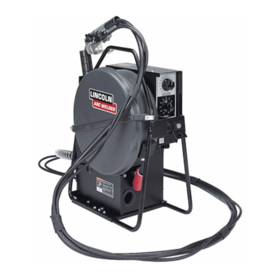
Portable innershield semiautomatic wire feeder
Hide thumbs
Also See for LN-23P:
- Technical specifications (2 pages) ,
- Operator's manual (28 pages) ,
- Service manual (55 pages)
Table of Contents
Advertisement
Quick Links
Portable Innershield Semiautomatic Wire Feeder
For use with machines having Code Numbers:
Safety Depends on You
Lincoln arc welding and cutting
equipment is designed and built
with safety in mind. However,
your overall safety can be
increased by proper installation
... and thoughtful operation on
your part. DO NOT INSTALL,
OPERATE OR REPAIR THIS
EQUIPMENT WITHOUT READ-
ING THIS MANUAL AND THE
SAFETY PRECAUTIONS CON-
TAINED THROUGHOUT. And,
most importantly, think before you
act and be careful.
• Sales and Service through Subsidiaries and Distributors Worldwide •
Cleveland, Ohio 44117-1199 U.S.A. TEL: 1-888-935-3877 FAX: 216.486.1751 WEB SITE: www.lincolnelectric.com
All manuals and user guides at all-guides.com
RETURN TO M IN INDEX
LN-23P
9085
10242
10314
10892
10917
10918
11359
11360
11361
11362
SERVICE MANUAL
• World's Leader in Welding and Cutting Products •
Copyright© 2007 Lincoln Global Inc.
SVM176-A
July, 2007
Advertisement
Chapters
Table of Contents
Troubleshooting

Related Manuals for Lincoln Electric LN-23P


Summary of Contents for Lincoln Electric LN-23P
- Page 1 SVM176-A All manuals and user guides at all-guides.com RETURN TO M IN INDEX July, 2007 LN-23P Portable Innershield Semiautomatic Wire Feeder For use with machines having Code Numbers: 9085 10242 10314 10892 10917 Safety Depends on You 10918 Lincoln arc welding and cutting...
-
Page 2: Safety
Miami, Florida 33135 or CSA Standard W117.2-1974. A Free copy of “Arc Welding Safety” booklet E205 is available from the Lincoln Electric Company, 22801 St. Clair Avenue, Cleveland, Ohio 44117-1199. BE SURE THAT ALL INSTALLATION, OPERATION, MAINTENANCE AND REPAIR PROCEDURES ARE PERFORMED ONLY BY QUALIFIED INDIVIDUALS. - Page 3 SAFETY All manuals and user guides at all-guides.com ARC RAYS can burn. ELECTRIC SHOCK can kill. 3.a. The electrode and work (or ground) circuits 4.a. Use a shield with the proper filter and cover are electrically “hot” when the welder is on. plates to protect your eyes from sparks and Do not touch these “hot”...
- Page 4 SAFETY All manuals and user guides at all-guides.com WELDING SPARKS can CYLINDER may explode cause fire or explosion. if damaged. 6.a. Remove fire hazards from the welding area. 7.a. Use only compressed cylinders If this is not possible, cover them to prevent containing the correct shielding gas for the the welding sparks from starting a fire.
- Page 5 SAFETY All manuals and user guides at all-guides.com PRÉCAUTIONS DE SÛRETÉ zones où lʼon pique le laitier. 6. Eloigner les matériaux inflammables ou les recouvrir afin de Pour votre propre protection lire et observer toutes les instructions prévenir tout risque dʼincendie dû aux étincelles. et les précautions de sûreté...
-
Page 6: Table Of Contents
MASTER TABLE OF CONTENTS FOR ALL SECTIONS All manuals and user guides at all-guides.com Page Safety ..............................i-iv Installation..........................Section A Operation..........................Section B Accessories ..........................Section C Maintenance ..........................Section D Theory of Operation ......................Section E Troubleshooting and Repair ....................Section F Electrical Diagrams ......................Section G Parts Manual ..........................P-142 LN-23P... - Page 7 K350-1 Adapter Kit ........K276 Enclosed 50lb. Wire Reel Support ..... . LN-23P...
-
Page 8: Installation
INSTALLATION All manuals and user guides at all-guides.com TECHNICAL SPECIFICATIONS – LN-23P OPERATING ARC VOLTAGE Constant Voltage (CV) 14-50VDC (90VDC Maximum OCV) RATED CURRENT 250-350 Amps 60% Duty Cycle (Depending on Gun Used) WIRE SPEED RANGE 30-170 Inches Per Minute (IPM) (1.18-6.70 mm) -
Page 9: Safety Precautions
INPUT CABLE Push the wire drive section door latch towards the rear of the LN-23P and open the door. Route the For K316L-1 (6 pin connector) electrode cable through the large rubber grommet in... -
Page 10: Wire Drive Rollsand Guide Tubes
Adapter with three of the #10 self-tapping screws The LN-23P is shipped with the proper drive rolls and provided. Attach the triangular plate to the side of guide tubes factory installed. Do not adjust the idle roll the DC-600 adjacent to the control terminal strips tension adjusting screw. - Page 11 One or two LN-23Pʼs can be connected to a DC power source (constant voltage) with a K-350 or K350-1 Adapter Kit. If two LN-23Pʼs are connected, they can be set for different procedures but only one can be used at a time.
- Page 12 NOTES All manuals and user guides at all-guides.com LN-23P...
- Page 13 Making the Weld ..........LN-23P...
-
Page 14: Operation
• Turn OFF input power at welding power source • Lay the LN-23P flat with the wire reel cover up, before installation or changing drive roll and/or unclip the rubber retaining strap, and remove the guide tubes. - Page 15 When welding, set the wire feeder on the floor or hang proper feeding. If the idle roll tension must be relieved it near the work area as convenient. Place the LN-23P temporarily, see the Maintenance Section for proper to minimize the amount of spatter falling onto it.
- Page 16 NOTES All manuals and user guides at all-guides.com LN-23P...
- Page 17 Accessories ..........Section C LN-23P Gun and Cable Assemblies Chart ......
-
Page 18: Accessories
K-276 ENCLOSED WIRE REEL SUPPORT Required when using the LN-23P on any constant Bolts to the LN-23P frame for feeding wire from stan- voltage power source. Either one or two LN-23Pʼs can dard 50 lb. Innershield coils. Includes enclosure and be connected to the Adapter. - Page 19 Nameplates ..........LN-23P...
-
Page 20: Maintenance
1/4" long. To re-assemble, replace idle roll assembly, tension Every year examine the gear box and paint the gear spring, retainer, and tension screw. Adjust the tension teeth with moly-disulfide filled grease. screw as described above. LN-23P... - Page 21 If it trips again, be sure the gun cable is not being excessively bent, is clean, and is the prop- er size for the wire diameter being fed. If it still trips, look for a defective electrical component. LN-23P...
- Page 22 NOTES All manuals and user guides at all-guides.com LN-23P...
- Page 23 Optional Circuits ..........FIGURE E.1 GENERAL DIAGRAM VOLTMETER WIRE SPEED CONTROL REDUCED SPEED CONTROL 10KΩ, 4 W VOLTAGE CONTROL 10KΩ, 4 W LN-23P CONTROL P.C. BOARD 3.5 A CIRCUIT BREAKER 82V, 12J 567A BLACK...
-
Page 24: Theory Of Operation
The DC arc voltage from the power source is applied enclosed 14 lb. wire reel, analog voltmeter and various to the LN-23P by way of the electrode cable (-)and the input control and electrode cables. Work Sensing Lead (+). . Typically the work connection is through the control cable of the K350 Adapter. - Page 25 All manuals and user guides at all-guides.com FIGURE E.3 – CONTROL CIRCUITS. VOLTMETER WIRE SPEED CONTROL REDUCED SPEED CONTROL 10KΩ, 4 W VOLTAGE CONTROL 10KΩ, 4 W LN-23P CONTROL P.C. BOARD 3.5 A CIRCUIT BREAKER 82V, 12J 567A BLACK WHITE...
- Page 26 The K350 Adapter kits are used to interface one or In a two feeder system, triggering the second gun two LN-23P feeders to a Lincoln CV power source. while one is welding may cause the feeder in use Figure E.4 shows a typical two feeder connection to shut down.
- Page 27 Relay Board and the relays. It is also the low connections that allow the voltage control, the welder voltage trigger circuit supply for the LN-23P. output (contactor) control and the Work Sense Lead (#21) to be switched from one feeder to the other.
- Page 28 NOTES All manuals and user guides at all-guides.com LN-23P...
- Page 29 • Never work on the inside of the machine without removing the input power. You can receive a life threatening electrical shock if you fail to do this. Only qualified technicians should perform installation, maintenance, and troubleshooting work on the machine. LN-23P...
-
Page 30: Troubleshooting And Repair
How To Use Troubleshooting Guide WARNING Service and Repair should only be performed by Lincoln Electric Factory Trained Personnel. Unauthorized repairs performed on this equipment may result in danger to the technician and machine operator and will invalidate your factory warranty. For your safety and to avoid Electrical Shock, please observe all safety notes and precautions detailed throughout this manual. -
Page 31: Pc Board Troubleshooting Procedures
Do not touch electrically hot parts. - If you return a PC board to The Lincoln Electric Company for credit, it must be in the static-shielding CAUTION bag. This will prevent further damage and allow prop- er failure analysis. - Page 32 6. Defective Motor or gearbox. CAUTION If for any reason you do not understand the test procedures or are unable to perform the tests/repairs safely, contact the Lincoln Electric Service Department for technical troubleshooting assistance before you proceed. Call 1-888-935-3877. LN-23P...
- Page 33 4. Defective K350 Adapter CAUTION If for any reason you do not understand the test procedures or are unable to perform the tests/repairs safely, contact the Lincoln Electric Service Department for technical troubleshooting assistance before you proceed. Call 1-888-935-3877. LN-23P...
- Page 34 • Perform the K350 Adapter test. CAUTION If for any reason you do not understand the test procedures or are unable to perform the tests/repairs safely, contact the Lincoln Electric Service Department for technical troubleshooting assistance before you proceed. Call 1-888-935-3877. LN-23P...
-
Page 35: Wire Feeder Test
WIRE FEEDER TEST WARNING Service and repair should be performed by only Lincoln Electric factory trained personnel. Unauthorized repairs performed on this equipment may result in danger to the technician or machine operator and will invalidate your factory warranty. For your safety and to avoid electrical shock, please observe all safety notes and precautions detailed throughout this manual. - Page 36 77 to 76 = 0 to 10kΩ as volts control is varied. 5. Move Reduced Speed Switch to Position 2 and If readings are not correct, check the cable see that motor speed decreases. and/or perform the Potentiometer test. LN-23P...
-
Page 37: Gun Test
GUN TEST WARNING Service and repair should be performed by only Lincoln Electric factory trained person- nel. Unauthorized repairs performed on this equipment may result in danger to the tech- nician or machine operator and will invalidate your factory warranty. For your safety and to avoid electrical shock, please observe all safety notes and precautions detailed throughout this manual. - Page 38 Position 2 = 0 ohms (continuity). (see Maintenance Section) and retest. If still If any of the above readings are incorrect, too high, replace the gun. that switch or cable is defective. 3. To check the Wire Feed cable: LN-23P...
-
Page 39: Feed Head Test
FEED HEAD TEST WARNING Service and repair should be performed by only Lincoln Electric factory trained person- nel. Unauthorized repairs performed on this equipment may result in danger to the tech- nician or machine operator and will invalidate your factory warranty. For your safety and to avoid electrical shock, please observe all safety notes and precautions detailed throughout this manual. - Page 40 F-12 F-12 All manuals and user guides at all-guides.com FEED HEAD TEST (cont.) FIGURE F.3 AMPS LN-23P Control Board 12 Volt Supply TEST PROCEDURE If drive rolls do not turn but the ammeter indicates 1. Remove the weld wire from the drive rolls.
-
Page 41: Potentiometer Test
POTENTIOMETER TEST WARNING Service and repair should be performed by only Lincoln Electric factory trained person- nel. Unauthorized repairs performed on this equipment may result in danger to the tech- nician or machine operator and will invalidate your factory warranty. For your safety and to avoid electrical shock, please observe all safety notes and precautions detailed throughout this manual. - Page 42 F-14 F-14 All manuals and user guides at all-guides.com POTENTIOMETER TEST (cont.) FIGURE F.4 Codes Below 10892 Codes 10892 & Above LN-23P Control Board TEST PROCEDURE VOLTAGE CONTROL POTENTIOMETER For codes above 10892 (8 pin connector) WIRE SPEED CONTROL POTENTIOMETER 1.
-
Page 43: K350(-1) Adapter Test
K350(-1) ADAPTER TEST WARNING Service and repair should be performed by only Lincoln Electric factory trained person- nel. Unauthorized repairs performed on this equipment may result in danger to the tech- nician or machine operator and will invalidate your factory warranty. For your safety and to avoid electrical shock, please observe all safety notes and precautions detailed throughout this manual. - Page 44 TROUBLESHOOTING AND REPAIR F-16 F-16 All manuals and user guides at all-guides.com K350(-1) ADAPTER TEST (cont.) FIGURE F.5 TEST SET-UP Control Terminal Strip Control Transformer Wire Feed Terminal Strip A Wire Feed Terminal Strip B 120vac Switch B Switch A LN-23P...
- Page 45 SHORT (0Ω) SHORT (0Ω) SHORT (0Ω) nections Perform 4 to 2A ---- OPEN (∞) SHORT (0Ω) OPEN (∞) 1CR or PC Bd. tests in 4 to 2B ---- OPEN (∞) OPEN (∞) SHORT (0Ω) 2CR or PC Bd. Step 6 LN-23P...
-
Page 46: Calibration Check
10. Set the Wire Speed Control to 100 ipm and check that the speed is 100 ipm +/-2. 11. Put the Reduced Speed Switch in Position 2. 12. Feed wire and check that the reduced speed is 83 ipm +/-3. LN-23P... - Page 47 Schematic Diagram for G4184-3 (L11838-3) ..................G-6 K350/K350-1 Adapter Schematic - (S17124)..................G-7 Control P.C. Board Assembly - (Codes below 10892) - (G1528-4) (Obsolete) ........G-8 Schematic Diagram for G1528-4 Control Board (L6518)..............G-3 Control P. C. Board Assembly (Codes 10892 and higher) - (G4184-3)..........G-9 LN-23P...
- Page 48 ELECTRICAL DIAGRAMS WIRING DIAGRAM - ENTIRE MACHINE - (M14197) VOLTMETER WIRE SPEED CONTROL REDUCED SPEED CONTROL 10KΩ, 4 W INDICATES CONNECTOR CAVITY No. VOLTAGE CONTROL 10KΩ, 4 W LN-23P CONTROL P.C. BOARD 3.5 A CIRCUIT BREAKER 82V, 12J 567A BLACK WHITE...
- Page 49 All manuals and user guides at all-guides.com ELECTRICAL DIAGRAMS SCHEMATIC - ENTIRE MACHINE (L6518) NOTE: This diagram is for reference only. It may not be accurate for all machines covered by this manual. LN-23P...
- Page 50 All manuals and user guides at all-guides.com ELECTRICAL DIAGRAMS WIRING DIAGRAM - K350 ADAPTER KIT (M14247) NOTE: This diagram is for reference only. It may not be accurate for all machines covered by this manual. LN-23P...
- Page 51 All manuals and user guides at all-guides.com ELECTRICAL DIAGRAMS WIRING DIAGRAM K350-1 ADAPTER KIT (M17514) NOTE: This diagram is for reference only. It may not be accurate for all machines covered by this manual. LN-23P...
- Page 52 All manuals and user guides at all-guides.com ELECTRICAL DIAGRAMS MACHINE SCHEMATIC FOR K350/K350-1 ADAPTER NOTE: This diagram is for reference only. It may not be accurate for all machines covered by this manual. LN-23P...
- Page 53 Lincoln Electric discourages board level troubleshooting and repair since it may compromise the quality of the design and may result in danger to the Machine Operator or Technician.
- Page 54 Lincoln Electric discourages board level troubleshooting and repair since it may compromise the quality of the design and may result in danger to the Machine Operator or Technician.
- Page 55 All manuals and user guides at all-guides.com ELECTRICAL DIAGRAMS SCHEMATIC FOR LN-23P CODES 10892 AND HIGHER (L11838-3) NOTE: This diagram is for reference only. It may not be accurate for all machines covered by this manual. LN-23P...
Need help?
Do you have a question about the LN-23P and is the answer not in the manual?
Questions and answers