
Summary of Contents for Secube AT-A1600
- Page 1 AT Series AT-A1600, ST-A1600, ST-A800, ST-A400, ST-S800, ST-S400 Digital Video Recorder User’s Manual (Rev. 2.0)
-
Page 2: Compliance Notice Of Fcc
User’s Manual WARNING RISK OF ELECTRIC SHOCK DO NOT OPEN WARNING: TO REDUCE THE RISK OF ELECTRIC SHOCK, DO NOT REMOVE COVER (OR BACK). NO USER-SERVICEABLE PARTS INSIDE. REFER SERVICING TO QUALIFIED SERVICE PERSONNEL. The lightning flash with arrowhead symbol, within an equilateral triangle, is intended to alert the user to the presence of uninsulated “dangerous voltage”... -
Page 3: Digital Video Recorder
Digital Video Recorder Important Safeguards 1. Read Instructions 13. Damage requiring Service Unplug this equipment from the wall outlet and refer servicing to All the safety and operating instructions should be read before the qualified service personnel under the following conditions: appliance is operated. -
Page 4: Table Of Contents
User’s Manual Table of Contents Chapter 1 - Introduction ………………...…………………..……...………………….7 Features ….…………………………………………………………………………………..7 Technical Overview …….……………………….…………………………………………8 Chapter 2 - Digital Video Recorder Layout …...….….….………………………9 Front Panel Layout …………………………………..…………………………………….9 Front LED Display…………………………………………………………………………. 12 Rear Panel Layout…………………………………………………………………………. 14 IR Remote Controller ……….…………………………………………………………….. 17 Chapter 3 - Installation …………………………………...……………………………. - Page 5 Digital Video Recorder Searching Video………………………………………….…………..…………………….37 Playing Video………………………..………………….……………………….………….42 Copying Video Clip…………………..……………………….…………..……………….48 Backup Video Data………………….…………….……………………………………….49 Checking DVR Status…………………….……………………………………………….51 Chapter 6 — Advanced Settings …………….….…………………………………..52 System Setting ……………….…………………….………………………………………51 General Setup …………………..…..……………..………………………………………54 Alarm Setup ……………………..……….……….……………………………………….56 System Manager….……………..…………………………………………………….57 Password Setup …………………..………………………………………………….……61 Configuration ………………………..……………………………………………………..62 Shutdown ………..……………………………….…………………………………………64 Camera Setting…………………………………..………………………………………….65 Setup …………………...………………….……………………………………………….65 Adjustment ………………….……………………………………………………………...66...
- Page 6 User’s Manual Appendix A - Reviewing Backup (Clip) Images ……………………………………..…... 96 Appendix B – How to use the Virtual Keyboard ……………………………………………97 Appendix C – Using Hot Keys ………………………………………………………………..98 Appendix D – Troubleshooting ……………………………………………………………… 99 Appendix E – Specifications ……………………………………………………………… 100 Appendix F –...
-
Page 7: Chapter 1 - Introduction
Digital Video Recorder Chapter 1 — Introduction 1.1 Features Your color digital video recorder (DVR) provides recording capabilities for four, eight or 16 camera inputs. It provides exceptional picture quality in both live and playback modes, and offers the following features: •... -
Page 8: Technical Overview
User’s Manual 1.2 Technical Overview Your DVR can replace both a time-lapse VCR and a multiplexer in a security installation. However, it has many features that make it much more powerful and easier to use than even the most advanced VCR. The DVR converts analog NTSC or PAL video to digital images and records them on a hard disk drive. -
Page 9: Chapter 2 - Digital Video Recorder Layout
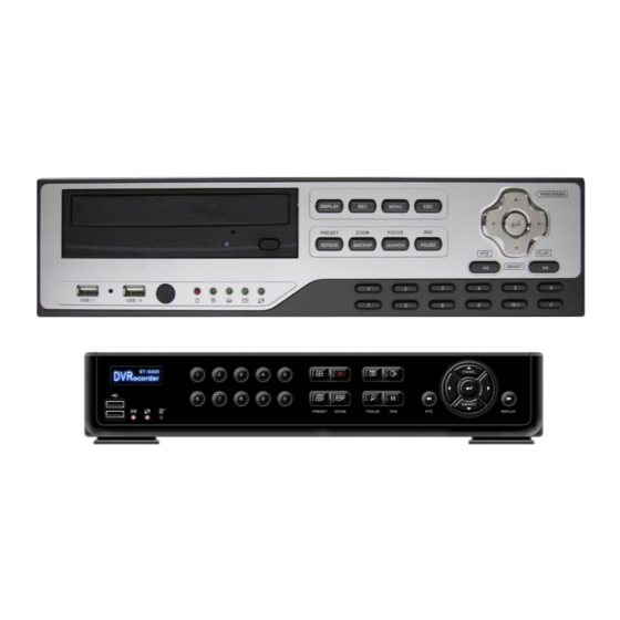
Digital Video Recorder Chapter 2 — Digital Video Recorder Layout NOTE: Your DVR should be completely installed before proceeding. Refer to Chapter 3 — Installation. 2.1 Front Panel Layout(AT-A1600, ST-A1600, ST-A800/A400) DVD-RW Arrow Buttons Display / REC / Menu / ESC... - Page 10 User’s Manual 2.2 Front Panel Layout(ST-S800, ST-S400) Arrow Buttons NUMERIC KEYPAD Display / REC / Menu / ESC ROTATE/ BACKUP / SEARCH / PAUSE DISPLAY/ZOOM /FOCUS / IRIS Record Network REMOCON FAST REWIND/PTZ SENSOR USB Ports FAST FORWARD/PLAY Figure — DVR front panel. (Others are similar.)
-
Page 11: Display Button
Digital Video Recorder The front panel looks and operates much like a VCR combined with a multiplexer. Many of the buttons have multiple functions. The following describes each button and control. Take a few minutes to review the descriptions. You will use these to initially set up your DVR and for daily operations. DISPLAY Button Pressing the DISPLAY button toggles between different display formats. -
Page 12: Enter Button
User’s Manual UP, DOWN, LEFT, RIGHT Arrow Buttons These buttons are used to navigate through menus and GUI. They are also used to control Pan and Tilt when in the PTZ mode. The arrow buttons can be used to move the position of the active cameo screen. These buttons also have the following functions. -
Page 13: Front Led Display
Digital Video Recorder Front LED Display (AT-A1600/ST-A1600/ST-A800/ST-A400) POWER LED: The POWER LED lights when the DVR is turned on. FAN LED: The FAN LED lights when the fan is working. HDD LED: The HDD LED lights when the HDD is being used. -
Page 14: Rear Panel Layout
2.2.1 AT-A1600/ST-A1600 Rear Panel Layout MONITOR OUTPUT (MAIN / SPOTS) CAMERA INPUT (1~16) LOOP OUT (1~16) RS485 AUDIO ALARM IN IN/OUT ALARM OUT AC POWER INPUT RS232 RJ45 ETHERNET PORT S-VIDEO OUT VGA MONITOR OUT Figure – AT-A1600/ST-A1600 DVR rear panel. - Page 15 Digital Video Recorder 2.2.2 ST-A800/ST-A400 Rear Panel Layout MONITOR OUTPUT (MAIN / SPOTS) AUDIO CAMERA INPUT (1~8) IN/OUT LOOP OUT (1~8) ALARM IN RJ45 ETHERNET PORT AC POWER INPUT ALARM OUT S-VIDEO OUT RS485 RS232 VGA MONITOR OUT NOT AVAILABLE FOR ST-A400 Figure –...
- Page 16 User’s Manual 2.2.3 ST-S800/ST-S400 Rear Panel Layout AUDIO IN(M2~M4) RS485 ALARM OUT ALARM IN5-8 for ST-S800 AUDIO DC POWER INPUT IN(M1)/OUT RJ45 CAMERA INPUT (1~8) ETHERNET PORT MONITOR OUTPUT (MAIN / SPOTS) RS232 VGA MONITOR OUT NOT AVAILABLE FOR ST-S400 Figure –...
-
Page 17: Ir Remote Controller
Digital Video Recorder 2.3 IR Remote Controller Display Menu Rotate Escape Number Lock (Log out) Enter ▲ Arrow / Panorama ◀ Arrow ▼ Arrow / Smart Fast Rewind / Fast Forward / Play Pause Search Backup Preset Zoom Iris Focus Figure –... -
Page 18: Chapter 3. Installation
User’s Manual Chapter 3. Installation DVD-RW Figure — SATA CONNECTOR Open the TOP COVER of the DVR and install HDDs. Up to 4 HDDs can be installed and they must be formatted after install. (Execute MENU->HDD SETUP->HDD INSTALL. See CHAPTER 6 HDD SETUP) In case of SATA 2.0 HDDs, set to 3Gb/s Operation. -
Page 19: Connecting The Video Source
Digital Video Recorder 3.1 Connecting the Video Source Figure — Video input connectors. Connect the coaxial cables from the video sources to the BNC Video In connectors. 3.2 Connecting the Loop Through Video Figure — Video Loop Through connectors. If you would like to connect your video source to another device, you can use the Loop BNC connectors. NOTE: The Loop BNC connectors are auto terminated. -
Page 20: Connecting Audio
User’s Manual 3.4 Connecting Audio NOTE: It is the user’s responsibility to determine if local laws and regulations permit recording audio. MIC (Audio In) (Audio In) Speaker Speaker (Audio Out) (Audio Out) .(option) Figure — 4Chanel Audio In and Out connectors. Figure —... -
Page 21: Connecting To The Rs485
Digital Video Recorder GND (Ground) NOTE: All the connectors marked GND are common. Connect the ground side of the Alarm input and/or alarm output to the GND connector. AO 1 TO 4 (Alarm Out) Figure — Alarm Output connector strips. The DVR can activate external devices such as buzzers or lights. -
Page 22: Connecting To The Network Port
User’s Manual 3.7 Connecting to the Network Port Figure — Network connector. The DVR can be networked using the 10/100Mb Ethernet connector. Connect a Cat5 cable with an RJ- 45 jack to the DVR connector. The DVR can be networked with a computer for remote monitoring, searching, configuration and software upgrades. -
Page 23: Connecting To The Ptz Camera Unit
Digital Video Recorder 3.10 Connecting to the PTZ Camera Unit Make a connection of PTZ unit to RS485 at the rear panel of DVR. (See the figure below) PTZ units currently being supported are Pelco-D/P, NVCC-Z42N, CyberDome(Kalatel), Samung, Samsung Techwin, Dongyang, Sungjin, Dongyang, DRX-500, DS120, Fastrax II, Sensormatic, PIH-7600, Eyeview Dome, ERNA Tech, DY-255RXB, AcutVista, Panasonic WV, CS950, PTC-410C DVR Rear Panel... -
Page 24: Chapter 4 - Quick Guide
User’s Manual Chapter 4 — Quick Guide 4.1 How to Install Install a Hard Disk Drive to your DVR after opening the upper case. Connect cameras to the Video In No. 1 ~ 16. Connect a Monitor to the Main(CCTV) or VGA. (If necessary, connect the spot monitor to the Spot A, B or Connect a Network cable to the Ethernet port. - Page 25 Digital Video Recorder Icon Remarks Exit button without saving from the main menu. Button for Day, Night, Weekend setting as well as other detailed menu setting From the setting value 8 + means that the minimum value is 8, there are higher numbers being set.
-
Page 26: Monitoring
User’s Manual 4.3 Monitoring Using front key pad : Select the desired split screen using the front Display button. To see the FULL screen, use the front numeric keys. Using mouse: Move the mouse to the bottom of screen then activate Bottom Menu to select the split screen. To see the FULL screen, click the left mouse button on a channel. -
Page 27: Chapter 5 - Operation
Digital Video Recorder Chapter 5 — Operation 5.1 Log-in to DVR This system classifies user category as ADMIN, SUPERUSER, USER limiting the access to system operation. Each log-in authority level and access level has been summarized as below, and ADMIN level overrides all. -
Page 28: Log-Out Dvr
User’s Manual 5.2 Log-out to DVR To log-out from the system, click the LOCK button at front panel to brute force log-out or click the Log-out button from the Top Menu using mouse. The DVR system automatically does log-out after a certain time is elapsed. Menu Timeout that has been set in System Setting is the time for predefined automatic log-out. -
Page 29: Live Monitoring
Digital Video Recorder 5.3 Live Monitoring NOTE: This chapter assumes your DVR has been installed and configured. If it has not, please refer to Chapters 3. Installation and 6. Advanced Settings. The DVR’s controls are similar to a VCR. As with a VCR, the main functions are recording and playing back video. - Page 30 User’s Manual Live Cameo Menu CAMERA CHANGE You can change the live camera to the selected channel. Press the ENTER button after highlighting the CAMERA CHANGE. The below pop-up menu will appear. Figure – CAMEO – CAMERA CHANGE. You can select a cameo camera and the video will be swapped to the cameo camera. RECORD CHANGE When selecting the RECORD CHANGE on the CAMEO menu, the below menu will be popped up.
- Page 31 User’s Manual FREEZE/FREEZE ALL You can freeze the live display screen by selecting the FREEZE or FREEZE ALL in the CAMEO menu shown in the following menu screen. You can freeze all the channels by selecting the FREEZE ALL until you press the FREEZE ALL again or you can freeze one channel by selecting FREEZE until you press the FREEZE again.
- Page 32 Digital Video Recorder TOP MENU At live mode, by pressing the upward arrow key it will show a TOP menu, just like the figure shown below. For mouse usage, position the mouse pointer to the upper side of the screen. Figure0 –...
-
Page 33: Live Cameo Menu
User’s Manual Button Remarks Whenever pressing the button, 1, 4, 7, 9, 10, 13, 16 screen display is sequentially showed up. It helps to monitor efficiently by selecting the choice of screen split. Display In the live mode, pressing the ROTATE button displays another screen whenever you press this button manually. -
Page 34: Ptz Control
Digital Video Recorder 5.4 PTZ Control The DVR can control multiple cameras that have Pan, Tilt and Zoom capabilities. Press the ENTER button to pop up the Live Cameo Menu and select PTZ to get into the PTZ mode. The PTZ can be controlled in split screens by mouse or front key buttons. -
Page 35: Speed Setup
User’s Manual Figure – PTZ SUB-MENU. Speed Setup: You can select the moving speed of the PTZ camera by choosing the speed between 1 to 8 after pressing SPEED. NOTE: When using mouse to move PTZ camera, the moving speed depends on the mouse location. When locating the mouse to the edge side out of center, the speed is getting faster. -
Page 36: Recording Video & Audio
Digital Video Recorder 5.5 Recording Video & Audio Recording Video Once you have installed the DVR following the instructions in Chapter 3 – Installation, it is ready to record. Unless you change the setup, the DVR will start recording when you press the REC button on the remote or front panel. -
Page 37: Searching Video
User’s Manual 5.6 Searching Video There are various ways in searching the recorded data on DVR. GOTO FIRST: Searching the earliest recorded data. GOTO LAST: Searching the latest recorded data. CALENDAR : Using the internal calendar program to search for the recorded video data by date/time. -
Page 38: Calendar Search
Digital Video Recorder GOTO FIRST When pressing the GOTO FIRST, the DVR will play back from the earliest recorded data. GOTO LAST When pressing the GOTO LAST, the DVR will play back from the latest recorded data which is 30 seconds earlier than the current time. -
Page 39: Record List
User’s Manual RECORD LIST Once you have pressed the RECORD LIST, your DVR will display a list with recorded video and Date information. Select a list and press the PLAY button to playback the recorded video. Figure – RECORD LIST. -
Page 40: Event Search
Digital Video Recorder EVENT SEARCH Select the EVENT SEARCH in the SEARCH menu. Figure – SEARCH LOG. Figure – SEARCH LOG RESULT. The EVENT SEARCH screen will display changeable Date/Time, recorded information and channel selection. You can change the date/time and select the channels that you want to search. You can search the recorded video by Motion, Alarm In and Video Loss by turning on or off. -
Page 41: Overlapped List
User’s Manual OVERLAPPED LIST Figure – OVERLAPPED LIST(1) You can have an overlapped list by selecting OVERAPPED LIST in the SEARCH menu. You can select one of the video files in the list and playback. Your DVR will create the overlapped video list caused by Date/Time changes or the DST (Daylight Saving Time). -
Page 42: Playing Video
Digital Video Recorder 5.7 Playing Video Normal Playback It means a conventional playback. It supports forward/backward playback as well as playback speed and pause. Single Step Playback Single step playbacks the screen display one frame at a time by pressing up/down button during the pause stage. -
Page 43: Normal Playback
User’s Manual Normal Playback Normal playback means a constant speed playback. Pressing PLAY button enables the display of video that has been searched through Searching Video. High-speed Playback During the playback, press Fast Rewind(▶▶) or Fast Forward(◀◀) button. Low-speed Playback After pressing the PAUSE button(∥) during playback, press Fast Rewind (▶▶) or Fast Forward (◀◀) to have low-speed playback. -
Page 44: Smart Playback
Digital Video Recorder Smart Playback It is an ideal playback for video with many movements. It is useful for fast checking of video clips. Pressing the Down Arrow button during playback or pressing the SMART button on the Down Playback Cameo menu will start the smart playback. -
Page 45: Full Screen
User’s Manual Playback Cameo Menu LIVE CAM CHANGE Live monitoring is possible during the playback by using the Playback Cameo Menu. Also, the live camera can be changed to playback by selecting a channel on the Camera Change menu of the Playback Cameo Menu. - Page 46 User’s Manual STILL IMAGE (JPEG) Still image on a full screen mode can be exported into JPEG image file. LIVE Switches selected cameo channel into LIVE image Zoom x2/ Zoom x4 Zoom is only active in 1 split screen mode. It is possible to zoom into 9 splits or 16 split screens. Users can maneuver the screen with the arrow keys.
- Page 47 Digital Video Recorder Button Remarks Search The first button to be used for search. Pressing the button displays Search Menu. Escape Cancel the playback and change to live screen mode. Enter Select Cameo from playback screen. Fast Playback speed up and down control for backward direction. Rewind Fast Playback speed up and down control for forward direction.
-
Page 48: Copying Video Clip
User’s Manual 5.9 Copying Video Clip This is the function that allows you to copy a part of video clip during play back into USB or other recording media. There are two ways of using it, with mouse or with front keys. Using the mouse Using the front keys - Select CUT AND SAVE from Cameo Menu... -
Page 49: Backup Video Data
Digital Video Recorder 5.10 Backup Video Data Backup to the internal CD-RW or DVD -RW You can backup the recorded video to the built-in CD-RW or DVD-RW. Press the BACKUP button on the front or remote. The following Backup screen will appear. Figure –... - Page 50 User’s Manual Figure – BACKUP(2) Figure – BACKUP(3) Selecting target button shows you the device pop-up. Device list window shows the list of all of the devices connected to the DVR. The types of the devices are CD-RW/DVD-RW of SATA TYPE, USB-STICK/HDD of USB TYPE and USB CD/DVD-RW , and the vendor model name and target’s capacity is shown on the list.
-
Page 51: Checking Dvr Status
Digital Video Recorder 5.11 Checking DVR Status Checking Status You can check the status of the DVR by selecting STATUS from the Top Live Cameo Menu. The status screen displays Record, Event, Network, Alarm, Disk and Key information. Figure – STATUS. -
Page 52: Chapter 6 - Advanced Settings
User’s Manual Chapter 6 — Advanced Settings Before using your DVR for the first time, you will need to establish the initial settings. This includes items such as time and date, camera, audio, remote control, record mode, network and password. Your DVR can be set up using various screens and dialog boxes. -
Page 53: System Setting
Digital Video Recorder 6.1 System Setting Configuring System Settings Select the SYSTEM SETUP in the main menu and it’s including General Setup, Alarm Setup, System Manager, Password, Configuration and Shutdown. -
Page 54: General Setup
User’s Manual GENERAL SETUP Select the GENERAL SETUP in the main menu and the GENERAL SETUP screen displays Video Format, Language, Date Format, Time Zone, Date Display, Date, Time, Key Tone, NTP, Unit Address, Base Camera Number and Menu Timeout. Figure –... - Page 55 Digital Video Recorder Video Format: You can select the Video Format between Auto, NTSC and PAL, according to your location. When selecting Auto, the DVR will detect the video format from the connected video sources. NOTE: Please don’t mix the video sources like NTSC and PAL cameras at the same time. It will cause errors in detecting the video format.
-
Page 56: Alarm Setup
User’s Manual ALARM SETUP Select the ALARM SETUP in the main menu and press the enter button. The ALARM SETUP screen displays the alarm outputs, 1-4. Figure – ALARM TYPE-ALARM OUT. You can enable or disable each alarm output by pressing the box below SIGNAL+ and select the proper alarm type between on and off. -
Page 57: System Manager
Digital Video Recorder SYSTEM MANAGER Select the SYSTEM MANAGER in the main menu and press the enter button. The HDD SETUP screen will display four pages, INSTALL, DISK MANAGER ,S/W UPGRADEand SYSTEM ENVIRONMENT. INSTALL Figure – INSTALL. The INSTALL page will show the HDD (Hard Disk Drive) status and you can initialize new hard disk drives by selecting the boxes below INSTALL and pressing the enter button. - Page 58 User’s Manual DISK MANAGER Select the second page, HDD SETUP – OVERWRITE and the following screen will appear. Figure – HDD SETUP – OVERWRITE(1) Figure – HDD SETUP – OVERWRITE(2) You can turn on or off the overwriting option by selecting the box beside HDD OVERWRITE. NOTE: When turning off the overwriting, your DVR will stop recording when the disk is full.
- Page 59 Digital Video Recorder Figure –PLAYBACK PROTECT Playback protect protects data in a certain time interval. If set to 3 days, data up to 3 days period is not overwritten. Can be set from 0~99 days and if set to 0, playback protect is off S/W UPGRADE Figure –...
- Page 60 Digital Video Recorder SYSTEM ENVIRONMENT Figure – SYS. ENVR Figure – S.M.A.R.T CHECK If CHECK ENABLE is on, HDD status and FAN SPEED can be checked. It is divided into check interval, temp.thresh and warning HDD temperature and Fan Speed can be checked according to the configured time interval and warning message can be set to popup, buzzer and off.
-
Page 61: Password Setup
User’s Manual PASSWORD SETUP An Administrator password is required to turn the system off, enter the setup screen, load default setups, clear all data, change system date and time and change the Administrator password. Highlight Password in the Main menu and press to enter the Password screen. Figure —... -
Page 62: Configuration
Digital Video Recorder CONFIGURATION CONFIGURATION – DVR SYSTEM You can save configurations in the DVR system or CD/USB and load from DVR system or CD/USB. Highlight the CONFIG in the main menu and press the enter button. The following screen will appear. Figure –... - Page 63 User’s Manual CONFIGURATION – CD-RW Select the 2 page, CD-RW. The below screen will appear. Figure – CONFIGURATION -CD-RW. You can save the current configuration to the CD/USB or you can also load the saved configuration from the CD/USB. NOTE: You can apply the same configuration to other DVR systems by using this function.
-
Page 64: Shutdown
Digital Video Recorder SHUTDOWN You can restart or shutdown your DVR by highlight the SHUTDOWN in the Main menu and pressing the enter button. The following screen will appear. Figure1 — SHUTDOWN(1) Figure – SHUTDOWN(2). Select the RESTART in the SHUTDOWN menu and press the enter button. You will be asked to confirm restarting the system. -
Page 65: Camera Setting
User’s Manual 6.2 Camera Setting This is the menu for Camera Setup, PTZ setup, Spot Setup, Sequence, Monitor Setup and Private Zone. SETUP Highlight SETUP in the main menu and press the enter button. The SETUP screen appears. Figure – SETUP (1) Figure –... -
Page 66: Adjustment
Digital Video Recorder NOTE: When selecting the OFF, the DVR doesn’t display the camera number and name. You can connect or disconnect the video input by highlighting the boxes below INSTALL+ and pressing the ENTER button. NOTE: The ENTER button allows you to select ON or OFF. NOTE: When selecting OFF, the DVR disconnects the video source so the camera can’t be displayed and recorded. -
Page 67: Ptz Setup
User’s Manual PTZ SETUP Highlight PTZ SETUP in the main menu and press the enter button. The PTZ SETUP screen appears. Figure – PTZ SETUP(1). Figure – PTZ SETUP(2). The PTZ SETUP screen displays the camera inputs in groups of four: 1-4, 5-8, 9-12 and 13-16. You can set up the baud rate, data bit, parity and stop bit by highlighting the boxes below PORT+ and press the enter button. -
Page 68: Spot Setup
Digital Video Recorder SPOT SETUP Your DVR can set up 3 spot monitors and assign cameras to each spot. Highlight the SPOT SETUP in the main menu and press the enter button. The following SPOT SETUP screen will appear. Figure – SPOT SETUP(1). Figure –... -
Page 69: Sequence
User’s Manual SEQUENCE You can set up the dwell time and the sequence for rotation. Select the SCREEN ROTATE in the main menu and press the enter button. The following screen will appear. Figure – SEQUENCE(1). Figure – SEQUENCE(2). The page dwell time is for page sequence in case of 4 or 9 split screens. You can select cameras for cameo sequence and set up the dwell time. -
Page 70: Monitor Setup
Digital Video Recorder MONITOR SETUP Select the MONITOR SETUP in the main menu and press the enter button. The Monitor Setup screen will be displayed. Figure – MONITOR SETUP. Resolution: VGA(CCTV) resolution can be modified. Resolution settings with LCD written at the back (e.g. 800 X 600/60Hz LCD) can only be seen through VGA monitors. -
Page 71: Private Zone
Digital Video Recorder PRIVATE ZONE Select the PRIVATE ZONE in the main menu and press the enter button. The Monitor Setup screen will be displayed. Figure – PRIVATE ZONE. ZONE ENABLE: Private Zone can be enable for LIVE only or for both LIVE + PLAYBACK. ZONE COLOR : choices of gray, black, white, and blue. -
Page 72: Recording Setting
User’s Manual 6.3 Record Setting Configuring Recording Settings Your DVR offers a variety of flexible recording modes. You can set it up to record all the time or to record events only. It can be set up to continue recording once the hard disk drive is full by recording over the oldest video, or you can set it up alert you when the hard disk is full and stop recording. -
Page 73: Schedule Setup
Digital Video Recorder SCHEDULE SETUP Highlight SCHEDULE SETUP in the main menu and press the enter button. The SCHEDULE SETUP screen appears. Figure – SCHEDULE SETUP. Figure – SCHEDULE SETUP – RESOLUTION. You can set up the night time period by highlighting the boxes beside NIGHT and pressing the enter button. NOTE: The day time period is changed automatically, according to the setting of the night time. -
Page 74: Time Record Setup
User’s Manual TIME RECORD SETUP Highlight TIME RECORD SETUP in the main menu and press the enter button. The TIME RECORD SETUP screen will be displayed. Figure – TIME RECORD SETUP. Figure – TIME RECORD SETUP – SPEED AND QUALITY. The TIME RECORD SETUP screen displays recording settings for Day, Night and Weekend. -
Page 75: Event Setup
Digital Video Recorder EVENT SETUP EVENT INPUT Highlight EVENT SETUP in the main menu and press the enter button. The EVENT SETUP screen appears. The DVR can be set to react to events differently. Each sensor can be assigned to a camera with different recording speed, video quality and dwell time. -
Page 76: Motion Setup
User’s Manual MOTION SETUP You can turn on or off motion events for each camera by toggling On and Off at box below EVENT+. Your DVR has 5 levels of sensitivity for motion and you can assign the sensitivity level by pressing the box below SENSE+. -
Page 77: Alarm In Setup
Digital Video Recorder ALARM IN SETUP Highlight the box below ALARM IN+ for a channel that you want to set up and press the enter button. The following ALARM IN screen will appear. Figure – EVENT SETUP – INPUT - ALARM IN. You can select Alarm Inputs which will be associated with the camera. -
Page 78: Event Record Setup
User’s Manual EVENT OUTPUT EVENT RECORD SETUP You can select the RECORD ON/OFF, SPEED, QUALITY or POST RECORDING dwell time in the EVENT OUTPUT menu by highlighting the below boxes and press the enter button. NOTE: The recording speed in the EVENT OUTPUT menu will be associated with the resolution setting in the SCHEDULE SETUP menu. -
Page 79: Event Action Setup
Digital Video Recorder EVENT ACTION SETUP You can set up event actions by toggling between ON and OFF for Alarm, Image or Preset and you can also set up the alarm dwell time by highlighting the DISPLAY button and press the enter button. Highlight the ▶button and press the enter button to change certain details in the sub-menu. -
Page 80: Audio Record Setup
User’s Manual AUDIO RECORD SETUP Highlight the AUDIO RECORD SETUP in he main menu and press the enter button. The AUDIO RECORD SETUP screen appears. Figure – AUDIO RECORD SETUP(AUDIO 4CHANEL). All audio channels can be recorded by selecting RECORD+ button at once and each individual channel also can be recorded by turning on each audio Camera and Audio connection setup can be modified Figure –... -
Page 81: Quick Setup
User’s Manual QUICK SETUP Highlight the QUICK SETUP in he main menu and press the enter button. The QUICK SETUP screen appears. Figure – QUICK STEUP In quick setup, both fps and quality of time/event record can be configured. Event record, Event action can be also configured. -
Page 82: Menual Record Setup
User’s Manual MANUAL RECORD SETUP Highlight the MANUAL RECORD SETUP in he main menu and press the enter button. The MANUAL RECORD SETUP screen appears. Figure – MANUAL RECORD STEUP Through REC button users can modify MANUAL RECORD settings for recording. -
Page 83: Network Setting
Digital Video Recorder 6.4 Network Setting Configuring Network Settings Control communication related setting from DVR. It not only sets for commonly using Ethernet and PSTN, but also monitors the status of server from a remote site through the Client and E-mail setting. -
Page 84: Ethernet Setup
User’s Manual ETHERNET SETUP You can turn on or off the dynamic IP by highlighting the box beside the DYNAMIC IP and pressing the enter button. Figure – ETHERNET SETUP(1). When turning off the Dynamic IP, you can enter the static IP information by highlighting the sub-menu button(▶) and pressing the enter button. -
Page 85: Serial Setup
Digital Video Recorder SERIAL SETUP Select the SERIAL SETUP in the main menu and press the enter button. The SERIAL SETUP screen appears. RS-232 SETUP When pressing the down list menu button (▼) on the RS-232 SETUP, it will show NONE, MODEM, EXTERNAL CONTROLLER and TEXT-IN. - Page 86 User’s Manual RS-485 INPUT SETUP When pressing the down list menu button (▼) on the RS-485 INPUT SETUP, it will show NONE, EXTERNAL CONTROLLER and TEXT-IN. Then, please select a proper RS-485 serial communication device that you want to use. You can connect the RS-485 devices like external keyboard controller or POS (Point Of Sale) device to the RS-485 terminal on the back of the DVR by following the keyboard or POS manufacturer’s instructions.
-
Page 87: Ddns Setup
After entering required information, please visit the domain address (ex. http://secube.dyndns.org) on the Internet Explorer. Then, the Web-browser client as shown below will appear on the Internet Explorer. -
Page 88: Client Setup
User’s Manual CLIENT SETUP Highlight the CLIENT SETUP in the main menu and press the enter button. The following CLIENT SETUP – CONNECT screen will appear. Figure – CLIENT SETUP – CONNECT. Figure – CLIENT SETUP-USER ACCOUNT(1). Enter the TCP Port for client connection. The default SMS port (TCP) is 7000 and 80 for Web Port (TCP). You can select the remote restart or remote configuration by highlighting the side boxes and press the enter button. - Page 89 Digital Video Recorder Highlight the ACCESS RANGE in the CLIENT SETUP menu to define the IP access range to the client. Figure – CLIENT SETUP-ACCESS RANGE(1). Figure – CLIENT SETUP-ACCESS RANGE(2). When an IP address is not in the access range, the IP address can’t access the server and the default range is ALL.
-
Page 90: Email Setup
User’s Manual E-MAIL SETUP Your DVR can notify any event to assigned e-mail addresses and you can set up e-mail addresses up to 6. Highlight the E-MAIL SETUP in the main menu and press the enter button. The following E-MAIL NOTIFICATION screen will appear Figure –... -
Page 91: Email Server Setup
Digital Video Recorder E-MAIL SERVER SETUP Figure – E-MAIL SEVER SETUP(1). Figure – E-MAIL SERVER SETUP(2). When DVR system is selected, e-mail is sent directly to the specified e-mail address. When SMTP server is selected, e-mail is sent to a SMTP server and then sent to the specified e-mail address... -
Page 92: System Information
User’s Manual 6.5 SYSTEM INFORMATION Checking System Information You can check the system log, status and version information. -
Page 93: System Log
Digital Video Recorder SYSTEM LOG You can check the system log by selecting the SYSTEM LOG in the main menu. The below screen will show up. Figure – SYSTEM LOG. You can move to the previous page or next pages by pressing PREV or NEXT button in the SYSTEM LOG menu. - Page 94 User’s Manual Figure – STATUS (3). Figure – STATUS (4). In network, connection time, Id, transferred packet size and ip of currently connected clients can be checked. Alarm shows the status of Alarm in and Alarm output Figure – STATUS (5). Figure –...
-
Page 95: Version
Digital Video Recorder VERSION You can check the version of your DVR in the VERSION menu. Refer to the screen below. The VERSION screen will display the version information. Figure – VERSION. -
Page 96: Appendix A - Reviewing Backup (Clip) Images
User’s Manual Appendix A – Reviewing Backup (Clip) Images Save Print Full Screen Audio On/Off Show Play List Backward Open video file frame by frame Forward frame by frame Figure – DVR MINI PLAYER. Your DVR will download the Mini Player with the backup files automatically. You can play the backup files with the DVR Mini Player on your PC and convert the files to .JPG or .AVI format. -
Page 97: Appendix B - How To Use The Virtual Keyboard
Digital Video Recorder Appendix B – How to use the virtual keyboard Figure – VIRTUAL KEYBOARD. You will be using the virtual keyboard when setting up the DVR. Highlight the button and press the enter button to enter. The ↑ button will switch the page to the 2 page showing Capital letters, the ←... -
Page 98: Appendix C - Using Hot Keys
User’s Manual Appendix C – Using Hot Keys Smart Playback: Press the down arrow button (▼) when playing back video. In the Smart Playback mode, your DVR will play back the recorded video that has motions only. Panorama Playback: Press the UP arrow button (▲) in a single channel playback. NOTE: The Panorama playback can be entered in single channel screen only. -
Page 99: Appendix D - Troubleshooting
Digital Video Recorder Appendix D - Troubleshooting Problem Possible Solution No Power • Check power cord connections. • Check power at the outlet. No Live Video • Check camera video cable and connections. • Check monitor video cable and connections. •... -
Page 100: Appendix E - Specifications
User’s Manual Appendix E – Specifications Basic Specification AT-A1600 i16 Channel composite videos Inputs iCCTV Monitor (NTSC/PAL), Video iCRT(VGA) Monitor i3 Spot CCTV Monitor(NTSC/PAL) Outputs 16 Channel loop out iVGA Resolution : 800x600 / 1024 x 768 / 1280x1024 / 1280x768 / 1366x768 60Hz... - Page 101 Digital Video Recorder Appendix E – Specifications Basic Specification ST-A1600 i16 Channel composite videos Inputs iCCTV Monitor (NTSC/PAL), Video iCRT(VGA) Monitor i3 Spot CCTV Monitor(NTSC/PAL) Outputs 16 Channel loop out iVGA Resolution : 800x600 / 1024 x 768 / 1280x1024 / 1280x768 / 1366x768 60Hz iNTSC : 480fps PAL : 400fps Display/Scree Monitoring...
- Page 102 User’s Manual Appendix E – Specifications Basic Specification ST-A800 i8 Channel composite videos Inputs iCCTV Monitor (NTSC/PAL), Video iCRT(VGA) Monitor i1 Spot CCTV Monitor(NTSC/PAL) Outputs 8 Channel loop out iVGA Resolution : 800x600 / 1024 x 768 / 1280x1024 / 1280x768 / 1366x768 60Hz Display/Scree iNTSC : 240fps PAL : 200fps i 1 / 4 / 9 splits...
- Page 103 Digital Video Recorder Appendix E – Specifications Basic Specification ST-A400 i4 Channel composite videos Inputs iCCTV Monitor (NTSC/PAL), Video iCRT(VGA) Monitor i1 Spot CCTV Monitor(NTSC/PAL) Outputs 4 Channel loop out iVGA Resolution : 800x600 / 1024 x 768 / 1280x1024 / 1280x768 / 1366x768 60Hz iNTSC : 120fps PAL : 100fps Display/Scree Monitoring...
- Page 104 User’s Manual Appendix E – Specifications Basic Specification ST-S800 i8 Channel composite videos Inputs iCCTV Monitor (NTSC/PAL), Video iCRT(VGA) Monitor Outputs i1 Spot CCTV Monitor(NTSC/PAL) iVGA Resolution : 800x600 / 1024 x 768 / 1280x1024 / 1280x768 / 1366x768 60Hz iNTSC : 240fps PAL : 200fps Display/Scree Monitoring...
- Page 105 Digital Video Recorder Appendix E – Specifications Basic Specification ST-S400 i4 Channel composite videos Inputs iCCTV Monitor (NTSC/PAL), Video iCRT(VGA) Monitor Outputs i1 Spot CCTV Monitor(NTSC/PAL) iVGA Resolution : 800x600 / 1024 x 768 / 1280x1024 / 1280x768 / 1366x768 60Hz iNTSC : 120fps PAL : 100fps Display/Scree Monitoring...
-
Page 106: Appendix F - Dvr Faq
User’s Manual Appendix F – DVR FAQ General Q. What does Embedded Linux mean? A. Embedded Linux means that the operating system of the DVR has been implanted into the CPU (Central Processing Unit). This means that the system response time is faster, more stable, and that the core of the DVR is never affected by external factors, such as virus, hacking, and system failure due to hard drive abnormalities. - Page 107 Digital Video Recorder Network Q. Does it support dynamic IP? A. Yes. Turn on the Dynamic IP from Ethernet Setup allows you to use it. Q. Mail is not sent out. A. Please check all the setting in Ethernet Setup. Miscellaneous Q.
-
Page 108: Appendix G - Pstn Modem Setting
User’s Manual Appendix G – PSTN Modem Setting Follow the Steps : 1. Control Panel Network Connection Create New Connection 2. Select the Internet Connection for Networking 3. Select the manual connection while in preparation. Click Next button 4. Select telephone MODEM for the Internet connection. Click Next button 5. - Page 109 Digital Video Recorder...
Need help?
Do you have a question about the AT-A1600 and is the answer not in the manual?
Questions and answers