Carrier 58VLR Low-Boy Installation, Start-Up & Operating Instructions
For input capacities of 70,000—154,000; series 100
Hide thumbs
Also See for 58VLR Low-Boy:
- User's information manual (9 pages) ,
- User's information manual (8 pages) ,
- Installation, start-up, and operating instructions manual (19 pages)
Table of Contents
Advertisement
Visit www.carrier.com
Installation, Start-Up, and Operating Instructions
For Input Capacities of 70,000-154,000; Series 100
NOTE: Read the entire instruction manual before starting the
installation.
This symbol → indicates a change since the last issue.
TABLE OF CONTENTS
SAFETY CONSIDERATIONS .....................................................1
INTRODUCTION ..........................................................................3
LOCATION....................................................................................3
General ......................................................................................3
Location Relative to Cooling Equipment ................................4
INSTALLATION ...........................................................................4
Air for Combustion and Ventilation ........................................4
General ......................................................................................4
Unconfined Space................................................................4
Confined Space....................................................................5
Duct Work Recommendations..................................................5
Venting ......................................................................................6
Oil Burner .................................................................................7
Oil Connections ........................................................................7
Barometric Draft Control..........................................................7
Electrical Connections ..............................................................7
Filters.......................................................................................10
Operational Checkout .............................................................10
Sequence of Operation............................................................10
Combustion Check..................................................................11
Fan Adjustment Check ...........................................................12
Limit Control Check...............................................................14
For Year-Round Air Conditioning .........................................14
CARE AND MAINTENANCE...................................................14
General ....................................................................................14
Oil Burner ...............................................................................14
Heat Exchanger and Flue Pipe...............................................14
Blower Removal .....................................................................14
Manufacturer reserves the right to discontinue, or change at any time, specifications or designs without notice and without incurring obligations.
Book 1 4
PC 101
Catalog No. 535-80171
Tab 6a 8a
ama
Printed in U.S.A.
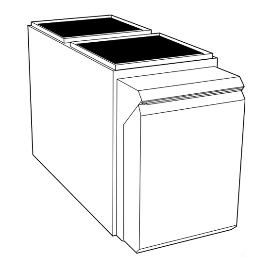
→ Fig. 1-58VLR Low-Boy Oil Furnace
SAFETY CONSIDERATIONS
FOR YOUR SAFETY
DO NOT STORE OR USE GASOLINE OR OTHER
FLAMMABLE VAPORS AND LIQUIDS IN THE VI-
CINITY OF THIS OR ANY OTHER APPLIANCE.
DO NOT ATTEMPT TO START THE BURNER
WHEN EXCESS OIL HAS ACCUMULATED, WHEN
THE FURNACE IS FULL OF VAPOR, OR WHEN
THE COMBUSTION CHAMBER IS VERY HOT.
CARBON MONOXIDE POISONING FIRE
EXPLOSION HAZARD
Failure to follow this warning could lead to sooting, fire,
explosion, and/or severe bodily harm.
For use with grade 1 or 2 Fuel Oil. Do not use Gasoline,
Crankcase Oil, or any Oil containing gasoline!
FIRE HAZARD
Failure to follow this caution may result in fire and property
damage.
Never burn garbage or paper in the heating system and never
leave rags, paper, or any flammable items around the unit.
Form 58VLR-2SI
Pg 1
58VLR
Low-Boy
Oil Furnace
A05024
2-05
Replaces: 58VLR-1SI
Advertisement
Table of Contents

Subscribe to Our Youtube Channel
Related Manuals for Carrier 58VLR Low-Boy


Summary of Contents for Carrier 58VLR Low-Boy
-
Page 1: Table Of Contents
General ..................4 Unconfined Space..............4 Confined Space..............5 Duct Work Recommendations..........5 Venting ..................6 A05024 Oil Burner .................7 → Fig. 1—58VLR Low-Boy Oil Furnace Oil Connections ................7 Barometric Draft Control............7 Electrical Connections ..............7 SAFETY CONSIDERATIONS Filters..................10 STARTUP, ADJUSTMENT, AND SAFETY CHECKOUT ..10 FOR YOUR SAFETY Operational Checkout .............10... - Page 2 ″ 20" 20" 20" ⁄ VENT CONN 10" 3" A98009 Dimensions (In.) UNIT DIMENSIONS FLUE HEIGHT RETURN OPENING SUPPLY OPENING VENT CONNECTION UNIT SIZE Depth Height Width 105–12 21-1/4 53-3/4 31-1/2 26-1/2 120–20 21-1/4 60-5/32 34-3/4 28-11/32 Fig. 2—Dimensional Drawing Only the latest issues of these codes should be used, and are available from either The National Fire Protection Agency, Bat- →...
-
Page 3: Introduction
UNIT DAMAGE HAZARD This oil furnace may be used for construction heat provided that: -The furnace operating conditions, including ignition, input rate, temperature rise and venting, are verified per instruc- tions in this manual. -The furnace is permanently installed with all electrical wiring, piping, venting and ducting installed according to these installation instructions. -
Page 4: Location Relative To Cooling Equipment
The furnace should be located as close as possible to chimney or In addition to air needed for combustion, process air shall be vent in order to keep vent connections short and direct. The provided as required for: cooling of equipment or material, furnace should also be located as near as possible to center of air controlling dew point, heating, drying, oxidation or dilution, safety distribution system. -
Page 5: Confined Space
2. Weatherstripping has been added on operable windows and All Air From Outside the Structure doors, and/or If outside air is supplied to a confined space, then the 2 openings 3. Caulking or sealants are applied to areas such as joints around must be equal and located as above. -
Page 6: Venting
→ Table 7—Electrical Data OPERATING VOLTS — UNIT MAX WIRE MAX FUSE OR VOLTAGE RANGE HERTZ— UNIT WIRE SIZE LENGTH (FT)† CKT BKR AMPS‡ PHASE AMPS GAGE Max.* Min.* 105–12 115–60–1 12.2 120–20 115–60–1 15.7 *Permissable limits of voltage range at which unit will operate satisfactorally. †Length shown is as measured 1 way along wire path between unit and service panel for maximum 2 percent voltage drop. -
Page 7: Oil Burner
Step 5—Oil Burner This furnace is supplied with a high-pressure atomizing retention FIRE HAZARD head-type burner (for use with grade 1 or 2 Fuel Oil). The Riello Failure to follow this warning could result in serious injury, oil burner operates with a prepurge period of 10 sec and a safety death, or property damage. - Page 9 A04183 A04185 Fig. 5—24 VAC Oil Furnace Wiring with 1-Speed Fig. 7—24 VAC Oil Furnace Wiring with 1-Speed Air Conditioner Heat Pump A04184 A04186 Fig. 6—24 VAC Oil Furnace Wiring with 2-Speed Fig. 8—24 VAC Oil Furnace Wiring with 2-Speed Heat Pump Air Conditioner...
-
Page 10: Filters
The variable-speed oil-fired unit will detect the humidistat OIL-FIRED HEATING MODE contacts opening on increasing humidity and reduce its airflow 1. The thermostat closes R to W. to approximately 85 percent of nominal cooling mode airflow. 2. Burner motor starts. The burner motor fan pre-purges the This reduction will increase the system latent capacity until combustion chamber and vent for 10 seconds, establishing the the humidity falls to a level which causes the humidistat... -
Page 11: Combustion Check
After which the BLWM operates at the appropriate oil (3.) Opening only R-Y/Y2 circuit switches BLWM to heat heating airflow. The BLWM reverts to continuous blower pump low-heat airflow. airflow after the heating cycle is completed. DEFROST c. When thermostat ″calls for low-cooling″, the BLWM keeps continuous-blower speed until the end of ″Short run″... -
Page 12: Fan Adjustment Check
Table 10—Burner Input And Nozzle Size Table 11a—58VLR105 Size Dip Switch Adjustment for Oil Heating Mode RIELLO OIL BURNER FURNACE FIRING PUMP INPUT RATE PRESSURE No. 40 Series Delavan SW1-HEAT SW4-DELAY (BTUH) GAL/HR (US)* (PSIG) Model Nozzle DIP SWITCH DIP SWITCH INPUT INPUT POSITION... - Page 13 NEUTRALS 120 VAC 120 VAC COOL HEAT OFF OFF OFF OFF ON ON ON ON DELAY OFF OFF OFF OFF ON ON ON ON LED7 LED4 LED3 LED5 LED7 LED8 LED1 Y/Y2 NOTES 1. The Red LED to the right of P-1 will illuminate whenever the limit switch is open. 2.
-
Page 14: Limit Control Check
Removal of any heat exchanger components which are sealed by Table 12c—58VLR120 Size Dip Switch CFM gaskets requires replacement of gasket. Adjustments in All Modes SW2-ADJUST HEATING CFM % COOLING CFM % DIP SWITCH POSITION INCREASE OR INCREASE OR CARBON MONOXIDE POISONING HAZARD DECREASE DECREASE Failure to replace any heat exchanger gaskets with new... - Page 15 → Table 13—58VLR105 Size Airflow Data (CFM) OIL HEATING MODE 24 VAC INPUT (R) ON W ONLY SW1-HEAT HEAT INPUT CFM with SW3-ADJ CFM with SW3-ADJ CFM with SW3-ADJ Dip Switch Position (USGPH) Dip Switch A Position Dip Switch B Position Dip Switch C Position A (1=OFF, 2=OFF) 0.75...
- Page 16 → Table 14—58VLR120 Size Airflow Data (CFM) OIL HEATING MODE 24 VAC INPUT (R) ON W ONLY SW1-HEAT HEAT INPUT CFM with SW3-ADJ CFM with SW3-ADJ CFM with SW3-ADJ Dip Switch Position (USGPH) Dip Switch A Position Dip Switch B Position Dip Switch C Position A (1=OFF, 2=OFF) 0.85...
- Page 17 SERVICE TRAINING Packaged Service Training programs are an excellent way to increase your knowledge of the equipment discussed in this manual, including: • Unit Familiarization • Maintenance • Installation Overview • Operating Sequence A large selection of product, theory, and skills programs is available, using popular video-based formats and materials.
- Page 20 Copyright 2005 CARRIER Corp. • 7310 W. Morris St. • Indianapolis, IN 46231 58vlr2si Manufacturer reserves the right to discontinue, or change at any time, specifications or designs without notice and without incurring obligations. Book 1 4 PC 101 Catalog No. 535-80171 Printed in U.S.A.
Need help?
Do you have a question about the 58VLR Low-Boy and is the answer not in the manual?
Questions and answers