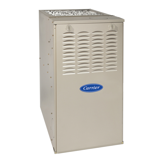
Carrier 58CTA Installation And Service Instructions Manual
2 stage deluxe induced-combustion
4-way multipoise furnace
series 110
Hide thumbs
Also See for 58CTA:
- Product data (17 pages) ,
- Installation, start-up, operating and service and maintenance instructions (56 pages)
Table of Contents
Advertisement
Installation, Start-up, Operating, and Service
The 58CTA/CTX Two-Stage, 4-way Multipoise Gas Furnaces offer unmatched comfort in their class with
ComfortHeat™ Technology in an 80% AFUE gas furnace. You get the benefits of a ComfortHeat™ Technology
furnace: reduced drafts, reduced sound levels, longer cycles, less temperature swings between cycles, and less
temperature differences between rooms. Its exclusive, intelligent microprocessor control adapts to the heating needs
of the home by automatically adjusting high and low heat times to maximize comfort. The 58CTA/CTX furnaces are
approved for use with natural or propane gas, and the 58CTX is also approved for use in Low NOx Air Quality
Management Districts.
Catalog No: 535-80124
2 Stage Deluxe Induced-Combustion
and Maintenance Instructions
-Series 110
THE PERFORMANCE 80 GAS FURNACE
CERTIFIED
®
Form No. 58CT-5SI
4-Way Multipoise Furnace
STANDARD FEATURES
- ComfortHeat™ Technology
Two-stage heating with single-stage thermostat
Very low operating sound through low-stage operation and
QuieTech™ system
- Media Filter Cabinet Available
- Microprocessor based "smart" control center
Adapts heating stages to meet demand
Dehumidification selection for summer-time cooling
Adjustable heating air temperature rise
Adjustable cooling airflow
ComfortFan™--Constant fan speed selectable from
thermostat
LED diagnostics and self test feature
Stores fault codes during power outages
- 4-way Multipoise furnace, 13 vent applications
- Hot surface ignition (HSI)
- Draft safeguard switch to ensure proper furnace venting
- All Models Chimney-Friendly when used with the
accessory vent kit.
- Insulated blower compartment
- Heat pump compatible
- Residential installations eligible for consumer financing
through the Retail Credit Program
Twinning in Upflow, Downflow and Horizontal
-
LIMITED WARRANTY
-
20-year warranty on "Super S™" heat exchanger
5-year parts warranty on all other components
-
58CTA/58CTX
1-05
Advertisement
Table of Contents

Related Manuals for Carrier 58CTA


Summary of Contents for Carrier 58CTA
- Page 1 Its exclusive, intelligent microprocessor control adapts to the heating needs of the home by automatically adjusting high and low heat times to maximize comfort. The 58CTA/CTX furnaces are approved for use with natural or propane gas, and the 58CTX is also approved for use in Low NOx Air Quality Management Districts.
-
Page 2: Important Information
Important Information Addendum to the Installation, Start-up, and Operating and Maintenance Instructions Series 110 or Series B 33 1/3” Mid-Efficiency Furnaces This furnace is equipped with the White-Rodgers Series G valve. This instruction sheet is to familiarize you with Series G gas valve and to be used to check and adjust gas pressure for proper installation and start-up. -
Page 3: Table Of Contents
2-Stage Deluxe Induced-Combustion 4-Way Multipoise Furnace Cancels: II 312A-45-3 II 312A-45-4 1-05 Installation, Start-up, Operating, and Service and Maintenance Instructions Series 110/B NOTE: Read the entire instruction manual before starting the Electrical Connection to J-Box .........21 installation. This symbol → indicates a change since the last issue. →... -
Page 4: Safety Considerations
28-7/8" 26-1/8" (FLUE COLLAR) 25-1/4" 2-7/16" 22-9/16" AIRFLOW 1-5/16" 19" 13/16" JUNCTION BOX 13/16" 1-1/8" LOCATION OUTLET 4-13/16" 5-15/16" 1/2" DIA. K.O.THERMOSTAT WIRE ENTRY 9-5/8" 11/16" 8-9/16" 7/8" DIA 1-3/4" DIA.RIGHT HAND 7-3/4" ACCESSORY GAS ENTRY 1/2" DIA THERMOSTAT 11-1/2" WIRE ENTRY 3-15/16"... -
Page 5: Introduction
→ Table 1—Dimensions (IN.) FILTER C.L. TOP AND FLUE MEDIA CABINET SUPPLY-AIR RETURN-AIR FURNACE SIZE BOTTOM COLLAR* SHIP WT. (LB) CABINET WIDTH WIDTH WIDTH FLUE COLLAR (IN.) SIZE (IN.) (IN.) (IN.) (IN.) (IN.) 045-08/024045 14-3/16 12-9/16 12-11/16 9-5/16 045-12/036045 14-3/16 12-9/16 12-11/16 9-5/16... - Page 6 INSTALLATION MINIMUM INCHES CLEARANCE TO COMBUSTIBLE CONSTRUCTION DISTANCE MINIMALE EN POUCES AUX CONSTRUCTIONS COMBUSTIBLES This forced air furnace is equipped for use with This furnace is approved for UPFLOW, DOWNFLOW, and HORIZONTAL installations. natural gas at altitudes 0-10,000 ft (0-3,050m). accessory kit, supplied...
-
Page 7: Codes And Standards
Step 6—Gas Piping and Gas Pipe Pressure Testing • US: NFGC; chapters 5, 6, 7, and 12 and National Plumbing Codes • CANADA: NSCNGPIC Parts 3, 4, and 5, and Appendices A, B, E and H. Step 7—Electrical Connections • US: National Electrical Code (NEC) ANSI/NFPA 70–2002 •... - Page 8 THE BLOWER IS LOCATED BELOW THE BURNER SECTION, AND CONDITIONED AIR IS DISCHARGED UPWARD. THE BLOWER IS LOCATED TO THE RIGHT OF THE BURNER SECTION, AND AIR CONDITIONED AIR IS DISCHARGED TO THE LEFT. THE BLOWER IS THE BLOWER IS LOCATED TO THE LEFT LOCATED ABOVE THE BURNER SECTION, AND...
-
Page 9: Location Relative To Cooling Equipment
→ FIRE, INJURY OR DEATH HAZARD Improper location or inadequate protection could result in fire or explosion. When the furnace is installed in a residential garage, the burners and ignition sources must be located at least 18 inches above the floor. The furnace must be located or protected to avoid damage by vehicles. - Page 10 → Table 2–Minimum Free Area Required for Each Combustion Air Opening or Duct to Outdoors TWO HORIZONTAL DUCTS SINGLE DUCT OR OPENING TWO OPENINGS OR VERTICAL DUCTS (1 SQ. IN./2,000 BTUH) (1,100 SQ. MM/KW) (1 SQ. IN./3,000 BTUH) (734 SQ. MM/KW) (1 SQ.
- Page 11 1 SQ IN. PER 4000 CIRCULATING AIR DUCTS VENT THROUGH ROOF BTUH* DUCTS OUTDOORS 12″ MAX 12″ 12" MAX 1 SQ IN. VENT PER 2000 THROUGH BTUH* ROOF 1 SQ IN. 1 SQ IN. PER 1000 BTUH* IN DOOR 4000 OR WALL BTUH* UNCONFINED...
-
Page 12: Installation
= combined input of all other than fan-assisted appli- other ances in Btu/hr = combined input of all fan-assisted appliances in Btu/hr ACH = air changes per hour (ACH shall not exceed 0.60.) → The following requirements apply to the Standard Method and to the Known Air Infiltration Rate Method. -
Page 13: Downflow Installation
⁄ ″ HORIZONTAL INSTALLATION ⁄ ″ FIRE, EXPLOSION, AND CARBON MONOXIDE ⁄ ″ POISONING HAZARD Failure to follow this warning could result in dangerous operation, serious injury, death, or property damage. Do not install the furnace on its back or hang furnace with ⁄... - Page 14 FURNACE (OR COIL CASING WHEN USED) PLENUM COMBUSTIBLE OPENING FLOORING DOWNFLOW FLOOR SUBBASE OPENING SHEET METAL PLENUM FLOOR OPENING A96283 Fig. 11—Floor and Plenum Opening Dimensions A96285 Fig. 12—Furnace, Plenum, and Subbase Installed on a Combustible Floor FURNACE CD5 OR CK5 COIL ASSEMBLY OR KCAKC COIL BOX...
- Page 15 Table 4—Opening Dimensions (In.) FURNACE PLENUM OPENING FLOOR OPENING CASING APPLICATION WIDTH Upflow Applications on Combustible or Noncombustible 12-11/16 21-5/8 13-5/16 22-1/4 Flooring (KGASB subbase not required) Downflow Applications on Noncombustible Flooring 12-9/16 13-3/16 19-5/8 (KGASB subbase not required) 14–3/16 Downflow applications on combustible flooring (KGASB 11-13/16 13-7/16...
- Page 16 " THREADED ROD 4 REQ. OUTER DOOR ASSEMBLY SECURE ANGLE IRON TO BOTTOM OF FURNACE WITH 3 #8 x " SCREWS TYPICAL FOR 2 SUPPORTS 8" MIN FOR DOOR REMOVAL 1" SQUARE, 1 " x 1 " x " ANGLE IRON OR UNI-STRUT MAY BE USED (2) HEX NUTS, (2) WASHERS &...
-
Page 17: Filter Arrangement
LINE CONTACT ONLY PERMISSIBLE BETWEEN LINES FORMED BY INTERSECTIONS OF THE TOP AND TWO SIDES OF THE FURNACE JACKET AND BUILDING JOISTS, STUDS, OR FRAMING. ″ OVER ALL ″ UNDER DOOR 1″ UNDER FURNACE TYPE-B EXTEND OUT 12″ OUT ENTRY VENT FROM FACE OF DOOR I N *... - Page 18 → Table 5—Air Delivery - CFM (With Filter)* EXTERNAL STATIC PRESSURE (IN. WC) FURNACE RETURN-AIR SPEED SIZE INLET High 1120 1075 1020 Bottom Med-High 024045 Med-Low Side(s) High 1465 1400 1325 1250 1175 1085 Bottom Med-High 1295 1260 1210 1155 1090 1015 036045...
-
Page 19: Return Air Connections
→ Table 5—Air Delivery - CFM (With Filter)* (Continued) EXTERNAL STATIC PRESSURE (IN. WC) FURNACE RETURN-AIR SPEED SIZE INLET High 2090 2010 1930 1835 1710 1590 1470 1335 1025 Bottom Med-High 1790 1755 1705 1640 1550 1465 1360 1210 048135 Med-Low 1545 1525... - Page 20 Fig. 18—Upflow Return Air Configurations and Restrictions A02075 Fig. 19—Downflow Return Air Configurations and Restrictions A02163 A02162 Fig. 20—Horizontal Return Air Configurations and Restrictions...
-
Page 21: Electrical Connections
→ Table 6—Maximum Capacity of Pipe* SUPPLY NOMINAL LENGTH OF PIPE (FT) MANUAL IRON INTERNAL SHUTOFF PIPE DIAMETER VALVE SIZE (IN.) (REQUIRED (IN.) SEDIMENT 0.622 TRAP 0.824 UNION 1.049 1-1/4 1.380 1400 1-1/2 1.610 2100 1460 1180 * Cubic ft of natural gas per hr for gas pressures of 0.5 psig (14–in. wc) or less and a pressure drop of 0.5–in wc (based on a 0.60 specific gravity gas). -
Page 22: 115-V Wiring
FIELD 24-VOLT WIRING FIELD 115-, 208/230-, 460-VOLT WIRING FACTORY 24-VOLT WIRING FACTORY 115-VOLT WIRING NOTE 2 1-STAGE THERMOSTAT FIVE FIELD-SUPPLIED TERMINALS WIRE FUSED DISCONNECT THREE-WIRE 208/230- OR HEATING- 460-VOLT ONLY THREE PHASE 208/230- W/W1 VOLT NOTE 1 Y/Y2 SINGLE 115-VOLT FIELD- JUNCTION PHASE SUPPLIED... -
Page 23: Electrical Connection To J-Box
→ Table 7—Electrical Data OPERATING VOLTS- MAXIMUM MAXIMUM UNIT MAXIMUM MINIMUM VOLTAGE RANGE FURNACE SIZE HERTZ- FUSE OR CKT BKR UNIT AMPS AMPACITY# WIRE LENGTH (FT)‡ WIRE GAUGE PHASE AMPS† Maximum* Minimum* 045-08/024045 115-60-1 7.42 045-12/036045 115-60-1 9.67 070-08/024070 115-60-1 7.22 070-12/036070 115-60-1... -
Page 24: Power Cord Installation In Furnace J-Box
NOTE: Check that duct on side of furnace will not interfere with 24-V WIRING installed electrical box. Make field 24-v connections at the 24-v terminal strip. (See Fig. 2. Remove the desired electrical box hole knockout and position 32.) Connect terminal Y/Y2 as shown in Fig. 25-31 for proper the hole in the electrical box over the hole in the furnace cooling operation. - Page 25 See notes 2, 5, 8, 10, 11 and 12 on the page following these figures See notes 1, 2, 4, 6, 7, 9, 10, 11, and 15 on the page following these figures A03179 A03180 Fig. 26—Two-Stage Furnace with Single-Speed Fig.
- Page 26 See notes 2, 11, and 12 on the page following these figures A03183 Fig. 30—Two-Stage Thermostat with Two-Stage Furnace and Two-Speed Air Conditioner See notes 1, 2, 4, 11, 14, 15, and 16 on the page following these figures A03181 Fig.
- Page 27 NOTES for Figures 25-31 1. Heat pump MUST have a high pressure switch for dual fuel applications. 2. Refer to outdoor equipment Installation Instructions for additional information and setup procedure. 3. Outdoor Air Temperature Sensor must be attached in all dual fuel applications. 4.
- Page 28 CHIMNEY INSPECTION CHART For additional requirements refer to the National Fuel Gas Code NFPA 54/ANSI Z223.1 and ANSI/NFPA 211 Chimneys, Fireplaces, Vents, and Solid Fuel Burning Appliances in the U.S.A. or to the Canadian installation Code CSA-B149.1 in Canada. Crown Rebuild condition: crown.
-
Page 29: General Venting Requirements
The following information and warning must be considered in addition to the requirements defined in the NFGC or the NSCNG- CARBON MONOXIDE POISONING HAZARD PIC. Failure to follow the steps outlined below for each appliance connected to the venting system being placed into operation could result in carbon monoxide poisoning or death. -
Page 30: Appliance Application Requirements
Canada (and U.S.A.)-This furnace is permitted to be vented into → Table B—Minimum Allowable Input Rating of a clay tile-lined masonry chimney that is exposed to the outdoors Space-Heating Appliance in below the roof line, provided: Thousands of BTU per Hour 1. - Page 31 SEE NOTES: 1,2,4,5,7,8,9 SEE NOTES: 1,2,4,7,8,9 on the page following on the page following these figures these figures A03208 A03211 Fig. 34—Upflow Application-Vent Elbow Up Fig. 37—Downflow Application-Vent Elbow Up SEE NOTES: 1,2,4,5,6,7,8,9,10 SEE NOTES: 1,2,3,4,7,8,9 on the page following these figures on the pages following these figures A03209...
- Page 32 SEE NOTES: 1,2,4,7,8,9 on the page following these figures SEE NOTES: 1,2,4,5,7,8,9 on the page following these figures A03213 Fig. 40—Horizontal Left Application-Vent Elbow Left A03215 Fig. 42—Horizontal Left Application-Vent Elbow Up SEE NOTES: 1,2,4,5,7,8,9 on the page SEE NOTES: 1,2,4,5,7,8,9 on the page following these figures A03214 A03216...
-
Page 33: Additional Venting Requirements
SEE NOTES: 1,2,4,5,7,8,9 A02068 Fig. 46—Horizontal Right Application-Vent Elbow Left Caution!! For the following applications, use the minimum vertical heights as specified below For all other applications, follow exclusively the National Fuel Gas Code MINIMUM FURNACE ORIENTATION VENT ORIENTATION FURNACE INPUT(BTU/HR) MINIMUM VERTICAL VENT HEIGHT (FT)** VENT DIAMETER (IN.)* 154,000... - Page 34 A04127 → Fig. 47—Using Tin Snips to Cut Tie Points NOTE: Vent connector length for connector sizing starts at furnace vent elbow. The 4 inch vent elbow is shipped for upflow configuration and may be rotated for other positions. Remove the 3 screws that secure vent elbow to furnace, rotate furnace vent elbow to position desired, re-install screws.
-
Page 35: Sidewall Venting
A04131 → Fig. 51—Remove Knockout with Hammer A04130 START-UP, ADJUSTMENT, AND SAFETY CHECK → Fig. 50—Hammer and Screwdriver Used for Step 1—General Knockout FIRE HAZARD Failure to follow this warning could result in a fire and lead to property damage, personal injury or death. This furnace is equipped with manual reset limit switches in the gas control area. -
Page 36: Adjustments
Table 8—2 Stage Furnace Setup Switch Description SETUP SWITCH NORMAL DESCRIPTION SWITCH NO. NAME POSITION OF USE When OFF, allows 2-stage operation with a single stage thermostat. Turn ON when using 2 stage thermostat to allow Low Heat opera- SW-1 Adaptive Heat Mode tion when R to W/W1 closes and High Heat operation when R to W/W1 and W2 close. - Page 37 LOW-FIRE ON/OFF Table 9–Altitude Derate Multipler for U.S.A. ADJUSTMENT SWITCH ALLEN SCREW (UNDER CAP) ALTITUDE PERCENT DERATE MULTIPLIER (FT) OF DERATE FACTOR* HIGH-FIRE ADJUSTMENT 0–2000 1.00 ALLEN SCREW 2001–3000 8–12 0.90 INLET (UNDER CAP) PRESSURE 3001–4000 12–16 0.86 4001–5000 16–20 0.82 5001–6000 20–24...
- Page 38 from heat exchangers. Radiant heat affects temperature rise readings. This practice is particularly important with straight-run ducts. b. When thermometer readings stabilize, subtract return-air temperature from supply-air temperature to determine air temperature rise. NOTE: If the temperature rise is outside this range, first check: 1.) Gas input for low heat operation.
- Page 39 Table 12—2 Stage Furnace Blower OFF Delay Setup Switch DESIRED HEATING MODE SETUP SWITCH SETUP SWITCH BLOWER OFF DELAY (SEC.) SW-2 SW-3 e. Re-install high-fire adjustment caps. c. Adjust air temperature rise by adjusting blower speed. Increase blower speed to reduce temperature rise. Decrease f.
-
Page 40: Check Safety Controls
a. Run furnace for at least 5 minutes. THERMOSTAT SUBBASE TERMINALS WITH b. Gradually block off return air with a piece of cardboard or THERMOSTAT REMOVED sheet metal until the limit trips. (ANITICIPATOR, CLOCK, ETC., MUST BE OUT OF CIRCUIT.) c. - Page 41 Table 13–Orifice Size and Manifold Pressure for Gas Input Rate (Tabulated Data Based On 22,000 Btuh High-Heat/14,500 Btuh for Low-Heat Per Burner, Derated 4 Percent For Each 1000 Ft Above Sea Level) SPECIFIC GRAVITY OF NATURAL GAS ALTITUDE AVG GAS 0.58 0.60 0.62...
- Page 42 Table 13–Orifice Size and Manifold Pressure for Gas Input Rate (Tabulated Data Based On 22,000 Btuh High-Heat/14,500 Btuh for Low-Heat Per Burner, Derated 4 Percent For Each 1000 Ft Above Sea Level) SPECIFIC GRAVITY OF NATURAL GAS AVG GAS ALTITUDE HEAT VALUE 0.58 0.60...
-
Page 43: Service And Maintenance Procedures
Table 13–Orifice Size and Manifold Pressure for Gas Input Rate (Tabulated Data Based On 22,000 Btuh High-Heat/14,500 Btuh for Low-Heat Per Burner, Derated 4 Percent For Each 1000 Ft Above Sea Level) SPECIFIC GRAVITY OF NATURAL GAS AVG GAS ALTITUDE HEAT VALUE 0.58 0.60... - Page 44 Table 14–Orifice Size and Manifold Pressure for Gas Input Rate(Tabulated Data Based On 21,000 Btuh High-Heat/14,500 Btuh for Low-Heat Per Burner, Derated 4 Percent For Each 1000 Ft Above Sea Level) SPECIFIC GRAVITY OF NATURAL GAS ALTITUDE AVG GAS 0.58 0.60 0.62 0.64...
- Page 45 Table 14–Tabulated Data Based On 21,000 Btuh High-Heat/14,500 Btuh for Low-Heat Per Burner, Derated 4 Percent For Each 1000 Ft Above Sea Level SPECIFIC GRAVITY OF NATURAL GAS AVG GAS ALTITUDE HEAT VALUE 0.58 0.60 0.62 0.64 RANGE AT ALTITUDE Orifice Manifold Orifice...
-
Page 46: Care And Maintenance
Table 14–Tabulated Data Based On 21,000 Btuh High-Heat/14,500 Btuh for Low-Heat Per Burner, Derated 4 Percent For Each 1000 Ft Above Sea Level SPECIFIC GRAVITY OF NATURAL GAS AVG GAS ALTITUDE HEAT VALUE 0.58 0.60 0.62 0.64 RANGE AT ALTITUDE Orifice Manifold Orifice... - Page 47 ACRDJ PRINTED CIRCIUT BOARD PRINTED CIRCIUT BOARD...
-
Page 48: Cleaning And/Or Replacing Air Filter
Table 15—FILTER SIZE INFORMATION (IN.) ELECTRICAL SHOCK AND FIRE HAZARD FILTER SIZE FURNACE FILTER CASING WIDTH TYPE Failure to follow this warning could result in personal injury, Side Return Bottom Return death or property damage. 14-1/2 16 X 25 X 1 14 X 25 X 1 Cleanable* Turn off the gas and electrical supplies to the unit before... -
Page 49: Cleaning Heat Exchanger
7. Hang control box from front of furnace casing and away from blower compartment. → ELECTRICAL SHOCK HAZARD 8. Remove 2 screws holding blower assembly to blower deck Failure to follow this warning could result in electrical shock, and slide blower assembly out of furnace. personal injury, or death. - Page 50 9/32” 11/32” 7/8” A02151 Fig. 57—Position of Igniter to Burner f. Hot surface igniter. A02150 g. Flame-sensing electrode Fig. 58—Position of Igniter to Burner h. Flame rollout switches. 6. Remove screws that fasten the collector box assembly to the cell panel. Be careful not to damage the collector box. Inducer assembly and elbow need not be removed from collector box.
-
Page 51: Sequence Of Operation
15. Reinstall vent connector on furnace vent elbow. Securely The furnace control performs a self-check, verifies the low-heat fasten vent connector to vent elbow with 2 field-supplied, and high-heat pressure switch contacts LPS and HPS are open, and corrosion-resistant, sheet metal screws located 180° apart. starts the inducer motor IDM in high-speed. - Page 52 f. Switching from Low-to High-Heat-If the furnace control 3. Cooling Mode-The thermostat “calls for cooling.” CPU switches from low-heat to high-heat, the furnace a. Single-Speed Cooling- control CPU will switch the inducer motor IDM speed from (See Fig. 26 for thermostat connections) low to high.
- Page 53 c. Two-Stage Thermostat and Two-Speed Cooling high-heat), allowing the furnace heat exchangers to heat up (See Fig. 30 for thermostat connections) more quickly, then restarts at the end of the blower-ON delay period at LO HEAT or HI HEAT speed respectively. NOTE: The air conditioning relay disable jumper ACRDJ must The blower motor BLWM will revert to continuous-blower be disconnected to allow thermostat control of the outdoor unit...
-
Page 54: Wiring Diagrams
Step 5—Troubleshooting control begins a normal inducer post-purge period and the blower switches to COOL speed after a 3 second delay. If the Refer to the service label. (See Fig. 55—Service Label.) R-to-W/W1-and-Y/Y2-and-G or R-to-W/W1-and-Y1-and- The Troubleshooting Guide can be a useful tool in isolating Y/Y2-and-G signals disappear at the same time, the blower furnace operation problems. - Page 58 Copyright 2005 Carrier Corporation 58ct5si Manufacturer reserves the right to discontinue, or change at any time, specifications or designs without notice and without incurring obligations. Book 1 4 Tab 6a 8a PC 101 Catalog No. See Cover Printed in U.S.A.
Need help?
Do you have a question about the 58CTA and is the answer not in the manual?
Questions and answers