Table of Contents
Advertisement
Available languages
Available languages
Quick Links
Advertisement
Chapters
Table of Contents

Related Manuals for Fanimation Islander


Summary of Contents for Fanimation Islander
-
Page 1: Ceiling Fan
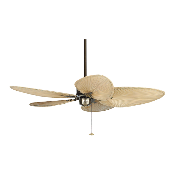
The Islander ® Ceiling Fan Standard & Damp Location Models Net Weight 19 lbs. Model No. FP320**1 OWNER’S MANUAL READ AND SAVE THESE INSTRUCTIONS Damp Location Model; Top of fan is marked, “Suitable For Use In Damp Locations”... -
Page 2: Table Of Contents
Fanimation. 7. Fanimation reserves the right to modify or discontinue any product at any time and may substitute any part under this warranty. 8. Under no circumstances may a fan be returned without prior authorization from Fanimation. The receipt of purchase must ac- company authorized returns and must be sent freight prepaid to Fanimation. -
Page 3: Unpacking Instructions
Fanimation. Substitution of parts or accessories not designated for use with this product by Fanimation could result in personal injury or property damage. Contact Ceiling Canopy/ your retail store for missing or damaged parts. -
Page 4: Electrical And Structural Requirements
Electrical and Structural Requirements Your new ceiling fan will require a grounded electrical supply line of 120 volts AC, 60 Hz, 15 amp circuit. The outlet box must be securely anchored and capable of withstanding a load of at least 50 lbs. Figure 1 depicts Ceiling different structural configurations that may be used for mounting the outlet box. - Page 5 How to Assemble Your Ceiling Fan (cont’d) Downrod NOTE: You will be using either the 6˝ downrod supplied with Ceiling Canopy your fan or an optional downrod purchased seperately. Setscrew 4. Loosen the two setscrews in the Downrod Support. Align the Clevis Pin holes in the Downrod with the holes in the Downrod Support.
-
Page 6: How To Hang Your Ceiling Fan
How to Hang Your Ceiling Fan ▲WARNING Ceiling To avoid possible electrical shock, be sure electricity is turned off at the main fuse box before hanging. NOTE: If you are not sure if the outlet box is grounded, contact a licensed electrician for advice, as it must be grounded for safe operation. -
Page 7: How To Wire Your Ceiling Fan - Pull Chain
How to Wire Your Ceiling Fan - Pull Chain If you feel that you do not have enough electrical wiring knowledge or experience, have your fan installed by a licensed electrician. ▲WARNING Black To avoid possible electrical shock, be sure electricity is Fan Wire Listed Black... -
Page 8: Installing The Canopy Housing
Installing the Canopy Housing NOTE: This step is applicable after the neccessary wiring is completed. (see pages 7) ▲WARNING To avoid possible fire or shock, make sure that the electrical wires are completely inside the canopy housing and not pinched between the housing and the ceiling. 1. -
Page 9: Maintenance
Mounting the Fan Blades (continued) 7. Attach Blade Holders to the bottom of the Rubber 8. Make sure the screws securing the Blade Holders to Flywheel using the 10-32 x ½˝ Flywheel Screws as shown the Flywheel are tight and that the Blade Holders are in Figure 19. -
Page 10: Parts List
Parts List Model #FP320**1 Ref. # Description Part # Hanger Bracket Assembly APG610BL Ceiling Canopy PG165 Hardware Bag Containing: 5/32˝-32 x19 mm Threaded Rods (2) 5/32˝ External Lockwasher (2) Knurled Knobs (2) HDWFP320** 10–32 x ½˝ Flywheel Screws (10) Wire Connectors (3) Chain Coupler Chain Fob Downrod/Hanger Ball Assembly Containing:... -
Page 11: Exploded-View Drawing
The Islander ® FP320**1 Exploded-View Ground Wire (Green) Ground Wire (Green) Figure 13 NOTE: The illustration shown is not to scale or its actual confi guration may vary... -
Page 12: Trouble Shooting
Trouble Shooting ▲WARNING For your own safety turn off power at fuse box or circuit breaker before trouble shooting your fan. Trouble Probable Cause Suggested Remedy 1. FAN WILL NOT START 1. Fuse or circuit breaker blown. 1. Check main and branch circuit fuses or circuit breakers. - Page 14 10983 Bennett Parkway Zionsville, IN 46077 (888) 567-2055 FAX (866) 482-5215 Outside U.S. call (317) 773-4113 Visit Our Website @ www.fanimation.com Copyright 2012 Fanimation 2012/09...
-
Page 15: Ventilador De Techo
The Islander ® Ventilador de techo Modelos para ubicaciones estándar y húmedas Peso neto 8,62 kg (19 lb) Modelo N.º FP320**1 MANUAL DEL PROPIETARIO LEA Y GUARDE ESTAS INSTRUCCIONES Modelo para ubicación húmeda; la parte superior del ventilador está marcada, “Apto para utilizar en lugares húmedos”... - Page 16 GARANTÍA LIMITADA DE POR VIDA DEL MOTOR - Si se produjera una falla en alguna de las partes del motor de su ventilador debido a un defecto en los materiales o en la fabricación durante el tiempo de vida del comprador original, Fanimation proporcionará la pieza de repuesto sin cargo una vez que el ventilador defectuoso sea devuelto a nuestro centro de servicios nacional.
-
Page 17: Instrucciones Para El Desempaque
Fanimation específicamente para el mismo. La sustitución de piezas o accesorios no designados por Fanimation para usar con este producto podría ocasionar lesiones personales o daños en el Capuchón/ ventilador. -
Page 18: Requisitos Eléctricos Y Estructurales
Requisitos eléctricos y estructurales Su nuevo ventilador de techo requiere una línea de suministro eléctrico con conexión a tierra de 120 voltios de CA, 60 Hz, circuito de 15 amperios. La caja de distribución eléctrica debe estar bien asegurada y debe ser capaz de Techo soportar una carga de, al menos, 22,7 kg (50 lb). - Page 19 Cómo ensamblar el ventilador de techo (cont.) Barral NOTA: Podrá utilizar el barral de 6˝ que viene con el ventilador Capuchón Pasador o un barral opcional que se adquiere por separado. Tornillo de fijación 4. Afloje los dos tornillos de fijación del soporte del barral. Alinee los orificios del pasador en el barral con los orificios del soporte del mismo.
-
Page 20: Cómo Colgar El Ventilador De Techo
Cómo colgar el ventilador de techo ADVERTENCIA Techo Para evitar posibles descargas eléctricas, asegúrese de que la electricidad esté desconectada en la caja de fusibles principal antes de colgar el ventilador. NOTA: Si no está seguro si la caja de distribución eléctrica tiene conexión a tierra, pida asesoramiento a un electricista autorizado, ya que la conexión a tierra es fundamental para un funcionamiento seguro. -
Page 21: Cómo Realizar La Instalación Eléctrica Del Ventilador De Techo - Cadena De Encendido/Apagado
Cómo realizar la instalación eléctrica del ventilador de techo - Cadena de encendido/apagado Si siente que no posee la experiencia o los conocimientos eléctricos necesarios, contrate a un electricista autorizado para instalar el ventilador. ADVERTENCIA Cable del Para evitar posibles descargas eléctricas, asegúrese de Caja de ventilador negro Negro... -
Page 22: Instalación De La Cubierta Del Capuchón
Instalación de la cubierta del capuchón NOTA: Este paso se debe realizar luego de completar la instalación eléctrica necesaria. (vea la página 21) ADVERTENCIA Para evitar posibles incendios o descargas eléctricas, asegúrese de que los cables eléctricos se encuentran completamente adentro de la cubierta del capuchón y de que no están aprisionados entre la cubierta y el techo. -
Page 23: Mantenimiento
Montaje de las aspas del ventilador (cont.) 7. Sujete los soportes de aspas a la parte inferior del 8. Asegúrese de que los tornillos que aseguran los volante de goma utilizando los tornillos del volante de soportes de aspas al volante estén bien ajustados y que 10-32 x ½˝... -
Page 24: Lista De Piezas
Lista de piezas Modelo N.° FP320**1 N.º de ref. Descripción Pieza N.º Unidad del soporte de suspensión APG610BL Capuchón PG165 Bolsa de accesorios que contiene: Varillas Roscadas de 5/32˝-32 x 19 mm (2) Arandelas de seguridad externas de 5/32˝ (2) Perillas estriadas (2) HDWFP320** Tornillos del volante de 10–32 x ½˝... -
Page 25: Plano De Despiece
® The Islander FP320**1 Despiece Cable de conexión a tierra (verde) Cable de conexión a tierra (verde) Figura 13 NOTA: La ilustración que se muestra no está hecha a escala y su configuración real puede variar... -
Page 26: Solución De Problemas
Solución de problemas ADVERTENCIA Para su propia seguridad, desconecte la electricidad de la caja de fusibles o disyuntor antes de solucionar problemas en su ventilador. Problema Causa posible Solución sugerida 1. EL VENTILADOR NO El fusible o el disyuntor están fundidos. Revise los fusibles del circuito principal y derivado o los disyuntores. - Page 28 10983 Bennett Parkway Zionsville, IN 46077 Llame sin cargo al (888) 567-2055 FAX (866) 482-5215 Desde fuera de los EE.UU., llame al (317) 773-4113 Visite nuestro sitio web en www.fanimation.com Copyright 2012 Fanimation 2012/09...