Table of Contents
Advertisement
Quick Links
Advertisement
Table of Contents
Troubleshooting

Related Manuals for Miller Millermatic 350P


Summary of Contents for Miller Millermatic 350P
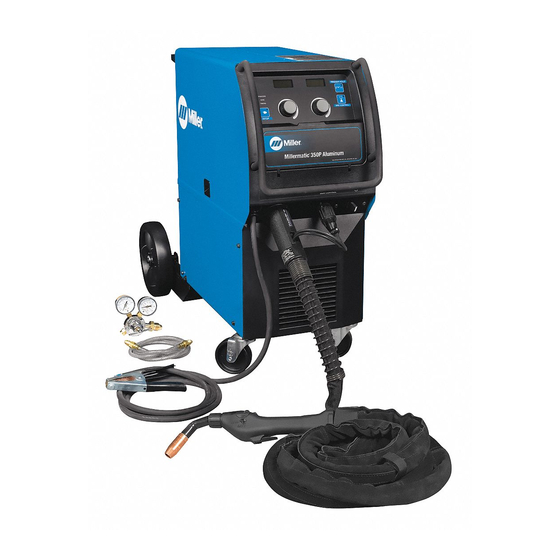
- Page 1 OM-1327 213 814AA 2009−10 Processes MIG (GMAW) Welding Pulsed MIG (GMAW-P) Flux Cored (FCAW) Welding Description Arc Welding Power Source and Wire Feeder Millermatic 350 And Millermatic 350P Visit our website at File: MIG (GMAW) www.MillerWelds.com...
- Page 2 We know you don’t have time to do it any other way. That’s why when Niels Miller first started building arc welders in 1929, he made sure his products offered long-lasting value and superior quality.
-
Page 3: Table Of Contents
TABLE OF CONTENTS SECTION 1 − SAFETY PRECAUTIONS - READ BEFORE USING ....... . . 1-1. - Page 4 TABLE OF CONTENTS SECTION 5 − PROGRAMMING ............. . 5-1.
-
Page 5: Section 1 − Safety Precautions - Read Before Using
SECTION 1 − SAFETY PRECAUTIONS - READ BEFORE USING som _2009−08 Protect yourself and others from injury — read and follow these precautions. 1-1. Symbol Usage DANGER! − Indicates a hazardous situation which, if Indicates special instructions. not avoided, will result in death or serious injury. The possible hazards are shown in the adjoining symbols or explained in the text. - Page 6 D Remove stick electrode from holder or cut off welding wire at FUMES AND GASES can be hazardous. contact tip when not in use. D Wear oil-free protective garments such as leather gloves, heavy Welding produces fumes and gases. Breathing shirt, cuffless trousers, high shoes, and a cap.
-
Page 7: Additional Symbols For Installation, Operation, And Maintenance
1-3. Additional Symbols For Installation, Operation, And Maintenance FIRE OR EXPLOSION hazard. MOVING PARTS can injure. D Do not install or place unit on, over, or near D Keep away from moving parts such as fans. combustible surfaces. D Keep all doors, panels, covers, and guards D Do not install unit near flammables. -
Page 8: California Proposition 65 Warnings
1-4. California Proposition 65 Warnings For Gasoline Engines: Welding or cutting equipment produces fumes or gases which contain chemicals known to the State of California to Engine exhaust contains chemicals known to the State of cause birth defects and, in some cases, cancer. (California California to cause cancer, birth defects, or other reproduc- Health &... -
Page 9: Section 2 − Consignes De Sécurité − Lire Avant Utilisation
SECTION 2 − CONSIGNES DE SÉCURITÉ − LIRE AVANT UTILISATION fre_som_2009−08 Se protéger et protéger les autres contre le risque de blessure — lire et respecter ces consignes. 2-1. Symboles utilisés DANGER! − Indique une situation dangereuse qui si on Indique des instructions spécifiques. - Page 10 Il reste une TENSION DC NON NÉGLIGEABLE dans LE SOUDAGE peut provoquer un les sources de soudage onduleur UNE FOIS incendie ou une explosion. l’alimentation coupée. Le soudage effectué sur des conteneurs fermés tels D Arrêter les convertisseurs, débrancher le courant électrique et que des réservoirs, tambours ou des conduites peut décharger les condensateurs d’alimentation selon les instructions provoquer leur éclatement.
-
Page 11: Dangers Supplémentaires En Relation Avec L'installation, Le Fonctionnement Et La Maintenance
ACCUMULATIONS LES BOUTEILLES peuvent exploser risquent de provoquer des blessures si elles sont endommagées. ou même la mort. Des bouteilles de gaz protecteur contiennent du gaz sous haute pression. Si une bouteille est endom- D Fermer l’alimentation du gaz protecteur en cas magée, elle peut exploser. -
Page 12: Proposition Californienne 65 Avertissements
Les PIÈCES MOBILES peuvent RAYONNEMENT HAUTE causer des blessures. FRÉQUENCE (H.F.) risque provoquer des interférences. D Ne pas s’approcher des organes mobiles. D Ne pas s’approcher des points de coincement D Le rayonnement haute fréquence (H.F.) peut tels que des rouleaux de commande. provoquer des interférences avec les équi- pements de radio−navigation et de com- munication, les services de sécurité... -
Page 13: Principales Normes De Sécurité
2-5. Principales normes de sécurité Safety in Welding, Cutting, and Allied Processes, ANSI Standard Z49.1, 25 West 43rd Street, New York, NY 10036 (téléphone : 212-642-4900, de Global Engineering Documents (téléphone : 1-877-413-5184, site site Internet : www.ansi.org). Internet : www.global.ihs.com). Standard for Fire Prevention During Welding, Cutting, and Other Hot Safe Practices for the Preparation of Containers and Piping for Welding Work, NFPA Standard 51B, de National Fire Protection Association,... - Page 14 OM-1327 Page 10...
-
Page 15: Section 3 − Installation
A complete Parts List is available at www.MillerWelds.com SECTION 3 − INSTALLATION 3-1. Specifications Max. Open Amps Input at Rated Output Circuit Rated Output 60 Hz 200 V 230 V 460 V 575V Voltage 300 A at 350 A at 13.1 11.2 Single-Phase... -
Page 16: Volt-Ampere Curve
A complete Parts List is available at www.MillerWelds.com 3-3. Volt-Ampere Curve Normal Volt-Ampere Curves The volt-ampere curves show the M AXVO LTS normal minimum and maximum M INVOLTS voltage and amperage output capabilities of the welding power source. Curves of other settings fall between the curves shown. -
Page 17: Installing Work Clamp
A complete Parts List is available at www.MillerWelds.com 3-5. Installing Work Clamp Work Cable Boot Route cable through front panel opening. Slide boot onto work cable. Negative (−) Output Terminal Connect cable to terminal and cover connection with boot. Close door. Tools Needed: 3/4 in. -
Page 18: Installing Welding Gun
A complete Parts List is available at www.MillerWelds.com 3-7. Installing Welding Gun Drive Assembly Gun Securing Knob Gun End Loosen securing knob. Insert gun end through opening until it bottoms against drive assembly (make sure gun end does not touch drive rolls). Tighten knob. -
Page 19: Connecting Spoolmatic) 15A Or 30A Gun
A complete Parts List is available at www.MillerWelds.com 3-8. Connecting Spoolmatic) 15A Or 30A Gun Gun Trigger Plug Insert plug into receptacle, and tighten threaded collar. Weld Cable Shielding Gas Hose Route weld cable and gas hose through opening in front panel. Positive Weld Output Terminal Connect weld cable to weld output terminal. -
Page 20: Connecting Xr Edge, Xr-A Gun, Xr-A Python, Or Xr - Aluma-Pro
A complete Parts List is available at www.MillerWelds.com 3-9. Connecting XR Edge, XR-A Gun, XR-A Python, Or XR - Aluma-Pro XR Edge guns prior to serial no. LE079101 require an adapter cord (part no. 195 498). Gun End Gun Liner Wire Outlet Guide Trim excess liner from end of gun so no more than 3/32 in. -
Page 21: Setting Gun Polarity For Wire Type
A complete Parts List is available at www.MillerWelds.com 3-10. Setting Gun Polarity For Wire Type Changing Polarity Polarity Changeover Information Always read and follow manufacture’s recommended polarity. Wire Drive Work Clamp Lead Assembly Lead Positive Negative Terminal Terminal Shown as shipped − Electrode Positive (DCEP): For solid steel, stainless steel, aluminum, or flux core with gas wires (GMAW). -
Page 22: Installing Gas Supply
A complete Parts List is available at www.MillerWelds.com 3-11. Installing Gas Supply Obtain gas cylinder and chain to running gear, wall, or other stationary support so cylinder cannot fall and break off valve. Cylinder Valve Remove cap, stand to side of valve, and open valve slightly. -
Page 23: Installing Wire Spool And Adjusting Hub Tension
A complete Parts List is available at www.MillerWelds.com 3-12. Installing Wire Spool and Adjusting Hub Tension Use compression spring with 8 in (200 mm) spools. When a slight force is needed to turn spool, tension is set. Tools Needed: 15/16 in. Ref. -
Page 24: Selecting Input Voltage (200/230/460 Volt Models Only)
A complete Parts List is available at www.MillerWelds.com 3-14. Selecting Input Voltage (200/230/460 Volt Models Only) Turn Off welding power source, disconnect input Be sure to reinstall all four screws power, and check voltage on securing relinking board in place. input capacitors according Section before... -
Page 25: Serial Number And Rating Label Location
A complete Parts List is available at www.MillerWelds.com 3-15. Serial Number And Rating Label Location The serial number and rating information for this product is located on back. Use rating label to determine input power requirements and/or rated output. For future reference, write serial number in space provided on back cover of this manual. 3-16. -
Page 26: Selection A Location And Connecting 1-Phase Input Power
A complete Parts List is available at www.MillerWelds.com 3-17. Selection A Location And Connecting 1-Phase Input Power Do not move or operate unit where it could tip. =GND/PE Earth Ground 18 in. (457 mm) for airflow Rear Panel Tools Needed: Ref. -
Page 27: Threading Welding Wire For Mig Gun
A complete Parts List is available at www.MillerWelds.com 3-18. Threading Welding Wire For MIG Gun Wire Spool Welding Wire Inlet Wire Guide Drive Roll Intermediate Wire Guide Outlet Wire Guide Pressure Adjustment Knob Gun Conduit Cable Lay gun cable out straight. Tools Needed: Hold wire tightly to keep it from unraveling. -
Page 28: Threading Welding Wire For Xr Edge, Xr-A Gun, Xr-A Python, Or Xr - Aluma-Pro
A complete Parts List is available at www.MillerWelds.com 3-19. Threading Welding Wire For XR Edge, XR-A Gun, XR-A Python, Or XR - Aluma-Pro Wire Spool Welding Wire Inlet Wire Guide Drive Roll Intermediate Wire Guide Outlet Wire Guide Pressure Adjustment Knob Gun Conduit Cable Lay gun cable out straight. -
Page 29: Threading Welding Wire Through Xr Guns
A complete Parts List is available at www.MillerWelds.com 3-20. Threading Welding Wire Through XR Guns Welding wire is electrically live when gun trigger is used to jog wire. For XR-A Edge Gun: Refer to Section 3-19 for instructions on feeding wire through welding pow- er source. -
Page 30: Section 4 − Operation
A complete Parts List is available at www.MillerWelds.com SECTION 4 − OPERATION 4-1. Controls Ref. 213 935-A Pulse Indicator Light Use button to access Timers, Process and 12 Weld Functions/Setup Indicator Wire menus. Lights Pulse only lights if unit has the pulse VOLTS illuminates in MIG welding mode Arc Control Button indicating volts in left display can be... -
Page 31: Weld Status
A complete Parts List is available at www.MillerWelds.com because gas valve is located inside spool gun. For MIG guns, wire will feed for up to 2 minutes while trigger is pressed, then wire drive system in unit will automatically shut off. For spool guns, wire will feed for up to 30 seconds before shutting off. -
Page 32: Weld Parameters For Mig Mode
A complete Parts List is available at www.MillerWelds.com 4-9. Weld Parameters For MIG Mode OM-1327 Page 28... -
Page 33: Weld Parameters For Pulse Mode
A complete Parts List is available at www.MillerWelds.com 4-10. Weld Parameters For Pulse Mode OM-1327 Page 29... -
Page 34: Section 5 − Programming
A complete Parts List is available at www.MillerWelds.com SECTION 5 − PROGRAMMING 5-1. MIG Welding Mode Ref. 213 935-A When the MIG light (2) is illuminated, the Depress SETUP (6) button again to ARC CONTROL unit is in MIG Welding mode. illuminate the WIRE (4) light. -
Page 35: Pulse Mig Welding Mode
A complete Parts List is available at www.MillerWelds.com 5-2. Pulse MIG Welding Mode Ref. 213 935-A OPERATION ARC CONTROL When the PULSE MIG (1, 2) is illuminated, the unit is in Pulse MIG Welding mode. Adjust right knob (9) for proper Wire Feed Pulse MIG (1, 2) welding mode: Depress SETUP speed and adjust left knob (8) to change... -
Page 36: Timers
A complete Parts List is available at www.MillerWelds.com 5-3. Timers Ref. 213 935-A To enter the TIMERS (5) menu depress the depressed and before the welding arc will DISP Display ( ) − Allows the Wire Speed SETUP (6) button 4 times or until the be allowed to be active. -
Page 37: Arc Times, Arc Starts, Hot Start (Aluminum Pulse Only), And Crater Fill
A complete Parts List is available at www.MillerWelds.com 5-4. Arc Times, Arc Starts, Hot Start (Aluminum Pulse Only), And Crater Fill Accessing the Arc Times, Arc Starts, Hot Start (aluminum pulse only), and Crater Fill data will also allow access to Software Version data and Motor Calibration function. -
Page 38: Setting Hot Start (Aluminum Pulse Only) Parameters
A complete Parts List is available at www.MillerWelds.com 5-5. Setting Hot Start (Aluminum Pulse Only) Parameters The factory default setting for Hot Start is “Auto” on 350P models. The Auto setting has preset parameters. Hot Start can also be set to “On” (manual) for customized settings or made inactive when set to Off. -
Page 39: Setting Crater Fill
A complete Parts List is available at www.MillerWelds.com 5-6. Setting Crater Fill Crater parameters are welding gun independent (i.e. crater fill can be on for a spool gun and off for a MIG gun). When using the same welding gun, MIG and pulse pro- grams are independent of each other;... -
Page 40: Recommended Crater Fill Parameters
A complete Parts List is available at www.MillerWelds.com 5-7. Recommended Crater Fill Parameters Recommended Crater Parameters Suggested Suggested Wire Sizes What Process What Material are You Using? (Diameter) are You Welding? Wire Types Shielding Gases 1/2” (12.7mm) OM-1327 Page 36... - Page 41 A complete Parts List is available at www.MillerWelds.com 3/8” 1/4” 3/16” 1/8” 19ga. 20ga. (1.05mm) (0.9mm) SC-187 212-A OM-1327 Page 37...
-
Page 42: System Reset
A complete Parts List is available at www.MillerWelds.com 5-8. System Reset RTMR Accessing the System Reset function will also allow access to Timer Reset ( ORST and Option Reset ( ) functions. The timer reset and option reset functions are for use by factory authorized service personnel only. -
Page 43: Motor Calibration Function
A complete Parts List is available at www.MillerWelds.com 5-9. Motor Calibration Function Ref. 213 935-A Perform this function after replacing wire Left Display Press and hold gun trigger. Wire drive speed will be overridden to 50 IPM for 12 drive motor and/or control circuit board. Right Knob motor calibration... -
Page 44: Set Up Push Motor Torque (Sup)
A complete Parts List is available at www.MillerWelds.com Welding wire birdnesting at the welding power source drive rolls may occur if this value is set too high. 5-10. Set Up Push Motor Torque (SUP) Ref. 213 935-A Setup Button Rotate the left knob counterclockwise over-torque limit of the push motor inside (CCW) to find the particular item, and rotate the welding power source. -
Page 45: Section 6 − Maintenance &Troubleshooting
A complete Parts List is available at www.MillerWelds.com SECTION 6 − MAINTENANCE &TROUBLESHOOTING 6-1. Routine Maintenance Maintain more often Disconnect power during severe before maintaining. conditions. n = Check Z = Change ~ = Clean l = Replace Reference * To be done by Factory Authorized Service Agent Every Months l Damaged Or Unreadable... -
Page 46: Measuring Input Capacitor Voltage
A complete Parts List is available at www.MillerWelds.com 6-3. Measuring Input Capacitor Voltage Significant DC voltage can remain on capacitors after unit is Off. Always check ca- pacitors as shown to be sure they have discharged before working on unit. Turn Off welding power source and disconnect input power. -
Page 47: Changing Drive Roll And Wire Inlet Guide
A complete Parts List is available at www.MillerWelds.com 6-4. Changing Drive Roll and Wire Inlet Guide Securing Screw Inlet Wire Guide Loosen screw. Slide tip as close to drive rolls as possible without touching. Tighten screw. .045 Groove .035 Groove Intermediate Guide Drive Roll The drive assembly comes... -
Page 48: Help Displays
A complete Parts List is available at www.MillerWelds.com 6-5. Help Displays HELP HELP HELP HELP HELP HELP HELP HELP HELP SAVE HELP 350P HELP HELP Displays a jog wire feed speed. OM-1327 Page 44... - Page 49 A complete Parts List is available at www.MillerWelds.com Help 4 Help 9 All directions are in reference to the Indicates gun trigger was pulled and held for Indicates a malfunction in Pulse MIG front of the unit. All circuitry referred to 2 minutes without a welding arc established function.
-
Page 50: Troubleshooting
A complete Parts List is available at www.MillerWelds.com 6-6. Troubleshooting Trouble Remedy No weld output; wire does not feed. Be sure line disconnect switch is On (see Section 3-16 or 3-17). Replace building line fuse or reset circuit breaker if open (see Section 3-16 or 3-17). Secure gun trigger connections (see Section 3-7). - Page 51 Notes OM-1327 Page 47...
-
Page 52: Section 7 − Electrical Diagram
SECTION 7 − ELECTRICAL DIAGRAM Figure 7-1. Circuit Diagram For Welding Power Source OM-1327 Page 48... - Page 53 246 030-A OM-1327 Page 49...
-
Page 54: Section 8 − Parts List
SECTION 8 − PARTS LIST 8-1. Drive Roll And Wire Guide Kits Base selection of drive rolls upon the following recommended usages: V-Grooved rolls for hard wire. U-Grooved rolls for soft and soft shelled cored wires. U-Cogged rolls for extremely soft shelled wires (usually hard surfacing types). V-Knurled rolls for hard shelled cored wires. - Page 55 Effective January 1, 2009 (Equipment with a serial number preface of LK or newer) This limited warranty supersedes all previous Miller warranties and is exclusive with no other Warranty Questions? guarantees or warranties expressed or implied. LIMITED WARRANTY − Subject to the terms and conditions...
- Page 56 Contact the Delivering Carrier to: File a claim for loss or damage during shipment. For assistance in filing or settling claims, contact your distributor and/or equipment manufacturer’s Transportation Department. © ORIGINAL INSTRUCTIONS − PRINTED IN USA 2009 Miller Electric Mfg. Co. 2009−01...
Need help?
Do you have a question about the Millermatic 350P and is the answer not in the manual?
Questions and answers
how do you replace LED lights and what is the part number for 350p LK030182B